EP2769847A2 - Système d'alimentation en encre pour imprimantes à jet d'encre - Google Patents
Système d'alimentation en encre pour imprimantes à jet d'encre Download PDFInfo
- Publication number
- EP2769847A2 EP2769847A2 EP14156726.3A EP14156726A EP2769847A2 EP 2769847 A2 EP2769847 A2 EP 2769847A2 EP 14156726 A EP14156726 A EP 14156726A EP 2769847 A2 EP2769847 A2 EP 2769847A2
- Authority
- EP
- European Patent Office
- Prior art keywords
- ink
- recirculation
- pressure
- pump
- supply system
- Prior art date
- Legal status (The legal status is an assumption and is not a legal conclusion. Google has not performed a legal analysis and makes no representation as to the accuracy of the status listed.)
- Granted
Links
Images


Classifications
-
- B—PERFORMING OPERATIONS; TRANSPORTING
- B41—PRINTING; LINING MACHINES; TYPEWRITERS; STAMPS
- B41J—TYPEWRITERS; SELECTIVE PRINTING MECHANISMS, i.e. MECHANISMS PRINTING OTHERWISE THAN FROM A FORME; CORRECTION OF TYPOGRAPHICAL ERRORS
- B41J2/00—Typewriters or selective printing mechanisms characterised by the printing or marking process for which they are designed
- B41J2/005—Typewriters or selective printing mechanisms characterised by the printing or marking process for which they are designed characterised by bringing liquid or particles selectively into contact with a printing material
- B41J2/01—Ink jet
- B41J2/17—Ink jet characterised by ink handling
- B41J2/18—Ink recirculation systems
-
- B—PERFORMING OPERATIONS; TRANSPORTING
- B41—PRINTING; LINING MACHINES; TYPEWRITERS; STAMPS
- B41J—TYPEWRITERS; SELECTIVE PRINTING MECHANISMS, i.e. MECHANISMS PRINTING OTHERWISE THAN FROM A FORME; CORRECTION OF TYPOGRAPHICAL ERRORS
- B41J2/00—Typewriters or selective printing mechanisms characterised by the printing or marking process for which they are designed
- B41J2/005—Typewriters or selective printing mechanisms characterised by the printing or marking process for which they are designed characterised by bringing liquid or particles selectively into contact with a printing material
- B41J2/01—Ink jet
- B41J2/17—Ink jet characterised by ink handling
- B41J2/175—Ink supply systems ; Circuit parts therefor
- B41J2/17596—Ink pumps, ink valves
Definitions
- the present invention relates generally to ink jet printers, and particularly, to ink jet printers that use a recirculating ink supply.
- drops of ink are jetted out of nozzles of an inkjet printhead towards a receiving layer which may be e.g. specially coated paper.
- a receiving layer which may be e.g. specially coated paper.
- an inkjet print head has an array of nozzles, each nozzle jetting ink to a different location possibly at the same time.
- the ink is jetted out of the nozzles by use of e.g. thermal or piezoelectric actuators creating a pressure wave. It is normally the intention that the size of the droplets can be kept constant or that there is a good control of the droplet size in printers capable of recording variable droplet sizes.
- One of the major parameters to ensure a constant drop size is that ink pressure at the printhead is stable and within a certain range suitable for the printhead used.
- Ink pressure at the printhead nozzle can be kept constant using several methods.
- small inkjet printers often employ a negative pressure generating member present in the ink reservoir mounted on the shuttle carrying the printhead.
- an ink tank is often equipped with a system regulating and stabilizing the pressure in the tank by directly controlling the ink pressure or the pressure of the air (atmosphere) above the ink.
- the ink supply system must be connected to the printhead with long tubes and each time the printhead carriage stops and starts during a print job, a pressure pulse is generated in the tubes and is transmitted to the printhead.
- long ink supply and return tubes mean significant thermal losses which conventional systems attempt to remediate with additional heating. However, this can result in overheating of UV curable inks which can promote premature curing and contribute to chemical instability.
- An ink supply system for ink jet printers includes a recirculation tank coupled to a recirculation pump configured to provide a substantially pulseless flow of ink.
- a heating assembly having an ink conduit formed into a spiral in thermal contact with at least one heating element receives ink from the pump and outlets to a sensor assembly with temperature and pressure sensors that measure ink parameters both as the ink enters a printhead and is returned from the printhead. The returned ink is then ported to a recirculation tank from which the pump draws the recirculating ink.
- An air pump is coupled to the recirculation tank in order to maintain a substantial vacuum within the tank.
- a light-weight ink supply system comprising:
- said recirculation tank is in fluid communication with an air pump operable for removing air from said recirculation tank.
- said heating assembly comprises a conduit through which ink is conveyed, said conduit formed into a double-spiral and in thermal contact with one or more heating elements.
- said ink fluid circuit further comprises a bypass line for conveying ink impelled by said recirculation pump into said recirculation tank in the event fluid pressure within said circuit increases beyond a threshold value.
- control system is a computer-based processor having a memory configured with control logic for executing the steps of:
- said compact housing member is mounted to a scanning printhead such that said compact housing member travels with the scanning printhead as the printhead scans.
- said recirculation tank is in fluid communication with an air pump operable for removing air from said recirculation tank.
- said heating assembly comprises a conduit through which ink is conveyed, said conduit formed into a double-spiral and in thermal contact with one or more heating elements.
- said ink fluid circuit further comprises a bypass line for conveying ink impelled by said recirculation pump into said recirculation tank in the event fluid pressure within said circuit increases beyond a threshold value.
- said control system is a computer-based processor having a memory configured with control logic for executing the steps of:
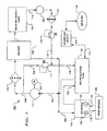
- the exemplary ink supply system 100 is essentially a fluid circuit and comprises a recirculation reservoir 101 having an outflow port coupled to the suction side 104 of a recirculation pump 111, the pressure side 106 of which is coupled to a heating assembly 115 with a filter 113 interposed therebetween.
- the location of the filter 113 may be any suitable location according to design preference. Locating the filter 113 upstream of the heating assembly 115 in some designs allows the heating assembly 115 to be located closer to the temperature sensors 105.
- Output from the heating assembly 115 is conveyed to a sensor block assembly 103 that includes pressure and temperature sensors 105, 107 respectively, and an printhead supply ink conduit 116 coupled to one or more recirculating printheads 109.
- Unejected ink is reintroduced into the supply system 100 via a return conduit 114.
- a first pair of pressure sensor 105 and temperature sensor 107 is affixed to the printhead supply ink 116 conduit and a second set of a pressure sensor 105 and a temperature sensor 107 is affixed to the return ink 114 conduit. Consequently, pressure and temperature measurements are taken prior to entry into the printhead and upon exit therefrom.
- Return ink 102 flows from the sensor block assembly 103 and is ported into the recirculation reservoir 101.
- the system 100 includes an air pump 119 in fluid communication with the recirculation reservoir 101, with an overflow detection sensor 121 intermediately disposed. Additionally, a check valve 117 is connected to a bypass line 129 from the pressure side 106 of the recirculation pump 111 with an output flowing into the recirculation reservoir 101.
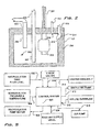
- Fig. 2 provides a cross-sectional view of an exemplary recirculation reservoir 101 which comprises a housing 205 defining the reservoir chamber 202.
- a fluid level detection assembly 203 including, for example, a float, extends to a suitable depth such that a minimum threshold of ink may be detected.
- the fluid level detection assembly 203 is configured to generate a fluid level signal 201 that is coupled to a computer-based control system (described infra ).
- An outflow conduit 207 is coupled to the suction side 104 of the recirculation pump 111, and an inflow conduit 209 extends into the chamber 202 for porting in return ink 102 from the sensor block 103.
- An inlet 212 is provided for receiving fill ink 110 introduced into the system at beginning of operation or when fluid level within the reservoir is low.
- the inlet 212 ports supply ink 110 onto a scalloped ledge 214 defined in the interior wall of the housing 205 to prevent ink splashing upward and interfering with the fluid level detection assembly 203 as well as to dissipate any air bubbles that may be introduced by the fill pump.
- An air outlet 216 is coupled to an air line 112 which is, in turn coupled to the air pump 119.
- Recirculation pump 111 is selected to pulselessly impel ink within the system and to be capable of self-priming. Of course, it should be specified to deliver ink to the printheads at the desired flow and pressure.
- recirculation pump 111 is a gear pump, and particularly, an external gear pump.
- recirculation pump 111 is driven by a motor 131 to which it is magnetically coupled to eliminate dynamic seals in favor of static seals, significantly improving reliability.
- the motor 131 is preferably a brushless motor. It will be appreciated that the speed of the recirculation pump 111 controls the pressure of the ink in the system 100.
- a heating assembly 115 is illustrated in greater detail with first and second housing members 301a, 301 b, and first and second planar heating elements 303a, 303b.
- Housing members 301a, 301b provide enclosed support for control leads 305a, 305b, which supply energy to the heating elements 303a, 303b, and are coupled to a controller (discussed in greater detail below).
- the heating assembly supports an ink conduit 307, preferably formed into a double spiral, having an intake 302 which receives ink from the recirculation pump 111 via the filter 113, and an outlet 304 coupled to an inlet to the sensor block assembly 103.
- First and second heating elements 303a, 303b are arranged on either side of the spiral.
- the length of the ink conduit 307 is sufficient to allow transfer of heat generated by first and second heating elements 303a, 303b, given fluid intake temperature, flow rate and volume, as would be understood by those skilled in the relevant arts.
- the conduit length is about three meters. This has demonstrated to be sufficient to allow the ink to leave the heating assembly 115 through outlet 304 and arrive at the sensor block 103 at about 40o C to about 50o C for use in the printheads.
- the heating assembly 115 is suitable to increase ink temperature by about 25o C from entry of the ink into the heating assembly 115 to its exit therefrom. However, upon first use of the system, several cycles may be required before the ink is at a suitable temperature.
- Typical prior art systems heat a reservoir which transfers heat to the ink. This is inefficient generally due to low amount of surface contact area between the tank and the ink and low turbulence in the tanks.
- Other systems use a heat exchanger with short length of heated tube (about 1 foot).
- the double-spiral tube arrangement comprising a longer tube (about three meters), is a cost effective and compact way to increase surface contact of the ink with the heated tubing, while the flow of ink provides mixing of the heated ink and insures there are no dead zones (ink sitting statically) where ink can be trapped and overheat.
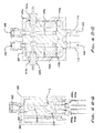
- the exemplary sensor block assembly 103 provides a mounting support structure for temperature and pressure sensors and, as illustrated in Figs. 4, through 4C .
- the sensor block assembly 103 comprises an outer housing assembly 401, 403 that encapsulates a mounting block 407 and a pressure sensor control board 405.
- the mounting block 403 includes a supply ink inlet channel 402 defined generally vertically therethrough having an inlet end 404 coupled to the heating assembly 115 outlet 304 and dual outlets 406a, 406b defined in printhead supply ink conduits 116 which are coupled to corresponding inlets of suitable printheads (not shown).
- the channel 402 in this example divides (Ref.
- a return ink channel 408 is defined through the mounting block 407 in parallel with the supply ink inlet channel 402 having dual inlets 410a, 410b defined by return ink conduits 114 coupled to corresponding outlets of suitable printheads (not shown). Inlets 410a, 410b merge, into a single channel 408 which extends through the block 407 to an outlet 412 which is coupled to the inflow conduit 209 of the recirculation tank 101.
- the mounting block 407 further comprises a first pair of mounting boreholes 414a, 414b defined in opposing block walls, each borehole extending to a depth to intersect its correspondingly nearest channel 402, 408.
- First and second temperature sensors 107a, 107b are inserted into boreholes 414a, 414b such that they will be in contact with fluid as either supply ink or return ink courses through the respective channels 408, 402.
- Temperature sensors 107 include control leads 409 coupled to the control system which, again, will be discussed in greater detail hereafter.
- the block 403 includes second pair of mounting boreholes 416a, 416b defined in opposing block walls dimensioned to receive respective pressure sensors 105a, 105b, for detecting fluid pressure in both the supply ink and the return ink channels 402, 408.
- the pressure sensors 107 are mounted to be in contact with the respective ink flows adjacent or coincident with the respective divides (Ref. C). Further, pressure sensors 107 are coupled to the control board 405 which is, in turn coupled to the control system. In this exemplary embodiment, pressure sensors 107 are co-located within the ink system and near the printheads. However, in an embodiment in which the primary system components (e.g., pumps, tanks, filters, heating assembly, etc.) must be farther away from the printheads, the pressure sensors should still be located near the printhead(s).
- the primary system components e.g., pumps, tanks, filters, heating assembly, etc.
- the exemplary system 100 preferably includes an air pump 119 in fluid communication with the recirculation tank 101 via an air 112 coupled to outlet 216.
- Air pump 119 may be a peristaltic pump that can supply or remove air from the recirculation tank 101 as needed for achieving the desired pressure at the sensor block assembly 103.
- the air pump 119 operation is controlled by a control system according to an control logic algorithm that is configured to maintain the desired pressure based upon on the current state, but includes running, standby and purging modes.
- the advantage of a peristaltic pump is that even with power off, the air is pinched and a vacuum in the recirculation tank 101 is maintained. This is a significant feature that saves ink, and reduces user frustration compared to prior systems.
- the air line 112 includes an overflow sensor 121 that can detect ink or foam entering the air line 112. In the event the sensor 121 detects ink or ink foam enters the line 112 a detection signal is issued from the sensor 121 to the control system which commands a shut down or a purge of the line.
- the system 100 may advantageously include a structure for introducing new ink comprising a bulk ink supply reservoir 123 coupled to the suction side 116 of a fill pump 125, the outlet of which is coupled to a filter 127.
- Fill ink 118 is ported to the recirculation tank 101 via the bypass line 129.
- a check valve 133 may be installed between the filter 127 and the bypass line 129 as well.
- Check valve 133 remains open during anytime fill ink 118 is being introduced into the system.
- the purpose of check valve 133 is that the vacuum maintained in the recirculation reservoir 101 can siphon ink from the supply reservoir 123 even when the fill pump 125 is not running. This will cause recirculation reservoir 101 to overfill, causing ink to flow up the air line 112 and shut the system down when the overflow sensor 121 is tripped. Consequently, check valve 133 remains closed when the fill pump 125 is not running.
- filters 113, 125 are preferably configured to remove gels and particles from the ink larger than about five microns (5 ⁇ ) in size.
- a contactor or degasser may optionally be included in the ink recirculation path, located anywhere between the recirculation pump 111 outlet and the sensor block assembly 103.
- recirculation pump 111 draws recirculation ink from the recirculation tank 101 which draws the ink from the suction side 104 and impels the ink to flow to the pressure side 106.
- ink After passing through filter 113, ink enters the heating assembly 115 from which it exits as heated ink 108 and is conveyed to the sensor block assembly 103 through which it flows before introduction through printhead supply ink conduit 116 into the printhead 109. Temperature and pressure of the ink is measured with temperature sensor 107 and a pressure sensor 105 before the ink flows to the printhead 109.
- check valve 117 will open allowing ink to flow through the bypass line back to the recirculation tank 101.
- pressure to the supply side of the sensor block assembly 103 as measured by the respective pressure sensor 105 will drop below a minimum threshold, initiating an alert signal that is issued to the control system which is configured to shut down operation until the overpressure event is remediated.
- ink level is monitored by the control system through the fluid level detection assembly 203.
- the control system is configured to initiate a re-supply of ink from the bulk supply tank 123 by energizing the fill pump 125.
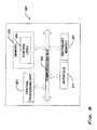
- Fig. 5 presents a functional diagram of an exemplary signal network as may be employed within the system 100 wherein the various components, described above, are coupled to a computer-based control system 500.
- control system 500 is configured to receive as input fluid level information signals 502, 504 from the recirculation tank 100 and the bulk ink supply tank 123, respectively, pressure and temperature signals 506 from the sensor block assembly 103, recirculation pump 111 and/or motor 131 speed 508, as well as fluid detection signal 518 from the air line overflow detector 121.
- the control system 500 is configured with control logic, described below, which causes the control system 500 to initiate various control commands depending upon the input received, namely: (1) energizing commands 508 to the recirculation pump motor 131 in the event system 100 pressure needs to be increased based on pressure signal 506 received from the sensor block assembly 103; (2) energizing, de-energizing and purge commands 510 to the air pump 119 in the event a vacuum in the recirculation tank abates or, in the case of a de-energizing or purge command, fluid is detected in the air line 112; (3) energizing and de-energizing commands 512 to the supply ink pump 125 in the event fluid level in the system 100 is too low; and (4) energizing commands 514 to the heating assembly 115 in response to temperature signals 506 that indicate ink temperature is outside of an acceptable range for operation. These same information paths are also used to shut the system down in case a check valve 117 is tripped open.
- the threshold for acceptable system pressure is defined as the pressure differential between the supply ink conduit 116 and the return conduit 114.
- the pressure sensors 105 relay a pressure signal to the control system 500.
- the control system 500 is configured with control logic which determines the measured differential and compares the measured differential to a threshold value or values, if acceptable system pressure may be a range. If the control system 500 determines the measured pressure differential is outside of acceptable pressure parameters, the control system 500 issues a command signal to the recirculation pump 111 motor 131 to increase or decrease speed, to increase or decrease system pressure, respectively.
- system temperature regulation is accomplished by measurement of the temperature of the ink at the printhead supply ink conduit 116 and the return ink conduit 114.
- a threshold for acceptable system temperature is defined as the average of the temperature with respect to the supply ink 116 and the return ink 114 conduits.
- the temperature sensors 107 relay temperature signals 506 to the control system 500 which is configured with control logic that determines the average measured temperature and compares the average measured temperature to a threshold value or values (if defined as a range of temperatures). If the control system 500 determines the average measured temperature is outside of acceptable temperature parameters, the control system 500 issues a command signal 514 to the heating assembly to increase or decrease heat within the heating assembly 115.
- the control system 500 may be one or more computer-based processors.
- a processor may be implemented by a field programmable gated array (FPGA), application specific integrated chip (ASIC), programmable circuit board (PCB), a microcontroller, or other suitable integrated chip (IC) device.
- FPGA field programmable gated array
- ASIC application specific integrated chip
- PCB programmable circuit board
- IC integrated chip
- a processor 600 in effect comprises a computer system.
- a computer system includes, for example, one or more central processing units (CPUs) 601 that are connected to a communication bus 603.
- the computer system can also include a main memory 605, such as, without limitation, flash memory, read-only memory (ROM), or random access memory (RAM), and can also include a secondary memory 607.
- the secondary memory can include, for example, a hard disk drive and/or a removable storage drive.
- the removable storage drive reads from and/or writes to a removable storage unit in a well-known manner.
- the removable storage unit represents a floppy disk, magnetic tape, optical disk, and the like, which is read by and written to by the removable storage drive.
- the removable storage unit includes a computer usable storage medium having stored therein computer software and/or data.
- the secondary memory 607 can include other similar means for allowing computer programs or other instructions to be loaded into the computer system.
- Such means can include, for example, a removable storage unit and an interface. Examples of such can include a program cartridge and cartridge interface (such as that found in video game devices), a removable memory chip (such as an EPROM, or PROM) and associated socket, and other removable storage units and interfaces which allow software and data to be transferred from the removable storage unit to the computer system.
- Computer programs are stored in the main memory and/or secondary memory. Computer programs can also be received via the communications interface. Such computer programs, when executed, enable the computer system to perform certain features of the present invention as discussed herein. In particular, the computer programs, when executed, enable a control processor 600 to perform and/or cause the performance of features of the present invention.
- a processor 600, and the processor memory may advantageously be configured with control logic or other substrate configuration representing data and instructions, which cause the processor to operate in a specific and predefined manner as, described hereinabove.
- the control logic may advantageously be implemented as one or more modules.
- the modules may advantageously be configured to reside on the processor memory and execute on the one or more processors.
- the modules include, but are not limited to, software or hardware components that perform certain tasks.
- a module may include, by way of example, components, such as, software components, processes, functions, subroutines, procedures, attributes, class components, task components, object-oriented software components, segments of program code, drivers, firmware, micro-code, circuitry, data, and the like.
- Control logic may be installed on the memory using a computer interface 611 coupled to the communication bus 603 which may be any suitable input/output device.
- the computer interface 611 may also be configured to allow a user to vary the control logic, either according to pre-configured variations or customizably.
- the control logic conventionally includes the manipulation of data bits by the processor and the maintenance of these bits within data structures resident in one or more of the memory storage devices.
- data structures impose a physical organization upon the collection of data bits stored within processor memory and represent specific electrical or magnetic elements.
- the control logic is generally considered to be a sequence of processor-executed steps. These steps generally require manipulations of physical quantities. Usually, although not necessarily, these quantities take the form of electrical, magnetic, or optical signals capable of being stored, transferred, combined, compared, or otherwise manipulated. It is conventional for those skilled in the art to refer to these signals as bits, values, elements, symbols, characters, text, terms, numbers, records, files, or the like. It should be kept in mind, however, that these and some other terms should be associated with appropriate physical quantities for processor operations, and that these terms are merely conventional labels applied to physical quantities that exist within and during operation of the computer.
- the software can be stored in a computer program product and loaded into the computer system using the removable storage drive, the memory chips or the communications interface.
- the control logic when executed by a control processor, causes the control processor to perform certain functions of the invention as described herein.
- features of the invention can be implemented using a combination of both hardware and software.
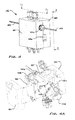
- Fig. 7 illustrates an arrangement of the system 100 which embodies a compact design that is particularly effective in scanning printhead printing applications.
- the components identified above namely the recirculation tank 101, the recirculation pump 111, its motor 131, and the control system 500 are mounted in a compact housing 701.
- the filter 113 is attached to the outlet from the pump extending above the housing 701 with a conduit connecting to the inlet of the heating assembly 115 which is mounted to the rear of the housing 701.
- the sensor assembly block 103 is mounted on the outside of the housing 701 such that it is connectable to one or more printheads, which may be scanning printheads.
- the system comprising an ink circuit mounted to, enclosed within, or otherwise supported by the housing 701 may be completely mounted to the printhead, ie., to a printhead carriage, such that the system travels with the printhead as it traverses the print media.
- the system 100 embodies several advantages over conventional recirculating ink supply systems.
- the compact system 100 needs far less space and weighs far less than previous systems so that it is suitable for use with scanning (i.e., moving with respect to the print media) printhead printers.
- the lack of complexity achieves a greater degree of reliability, less leakage, in addition to being easier to trouble-shoot in case a problem occurs.
- the compact design also costs less to manufacture resulting in a less expensive alternative for the printing industry.
- the recirculation tank 101 design coupled with the air pump results in less air foam in the ink circuit.
- most prior systems use two recirculation tanks 101.
- the fact that only one recirculation tank 101 is required in the presently described system is a significant advantage in size, weight and cost. It eliminates the bulk and weight resulting from a second tank, level sensor, air pump and overflow detector.
- the system 100 is extremely responsive to adjustment. For example, as stated above, the speed of the recirculation pump 111 controls the differential pressure of the ink from the supply side to the return side pressure sensors.
- Changing the pump speed results in a virtually immediate (e.g., about 200 milliseconds or less) change in differential pressure measured at the sensor block assembly 103.
- An additional advantage of one embodiment of the present design is that the air pump 119 controls the return side pressure, therefore both the differential pressure and the return side pressure measurements can be used to closely maintain respective target pressures.
- the recirculation pump is controlled to maintain the pressure difference and the air pump is controlled to maintain the return side target pressure.
- the heating assembly 115 design of the spiraled conduit 303 coupled with the speed of the ink within the circuit increases responsiveness to changes in temperature as well. System responsiveness is especially desirable in high-tempo, or dynamic printing conditions such as sustained high volume usage of ink or multiple instantaneous starting and stopping of the attached printhead jetting.
- ink supply systems 100 may be installed on a printer.
- ink supply systems often share a single control system and a vacuum pump, requiring a very complex control algorithm and often resulting in additional maintenance.
- multiple different types of inks may be used, each perhaps requiring unique temperature and pressure deposition parameters that a single control system must monitor with multiple sensors and control with multiple pumps.
- the system disclosed herein includes a dedicated control system, sensor array and controls, so the system 100 may be individually tailored to a specific ink independently of how other systems 100 are configured.
- the present invention comprises an ink supply system for ink jet printers that require recirculating ink. While particular embodiments of the invention have been described, it will be understood, however, that the invention is not limited thereto, since modifications may be made by those skilled in the art, particularly in light of the foregoing teachings. It is, therefore, contemplated by the appended claims to cover any such modifications that incorporate those features or those improvements that embody the spirit and scope of the system.
Landscapes
- Ink Jet (AREA)
Applications Claiming Priority (1)
| Application Number | Priority Date | Filing Date | Title |
|---|---|---|---|
| US13/777,845 US8926077B2 (en) | 2013-02-26 | 2013-02-26 | Ink supply system for ink jet printers |
Publications (3)
| Publication Number | Publication Date |
|---|---|
| EP2769847A2 true EP2769847A2 (fr) | 2014-08-27 |
| EP2769847A3 EP2769847A3 (fr) | 2016-11-23 |
| EP2769847B1 EP2769847B1 (fr) | 2021-02-17 |
Family
ID=50189527
Family Applications (1)
| Application Number | Title | Priority Date | Filing Date |
|---|---|---|---|
| EP14156726.3A Active EP2769847B1 (fr) | 2013-02-26 | 2014-02-26 | Système d'alimentation en encre pour imprimantes à jet d'encre |
Country Status (4)
| Country | Link |
|---|---|
| US (1) | US8926077B2 (fr) |
| EP (1) | EP2769847B1 (fr) |
| JP (1) | JP6231401B2 (fr) |
| ES (1) | ES2869435T3 (fr) |
Cited By (1)
| Publication number | Priority date | Publication date | Assignee | Title |
|---|---|---|---|---|
| CN106553454A (zh) * | 2015-09-24 | 2017-04-05 | 北大方正集团有限公司 | 循环供墨系统 |
Families Citing this family (30)
| Publication number | Priority date | Publication date | Assignee | Title |
|---|---|---|---|---|
| US10564025B2 (en) * | 2011-01-25 | 2020-02-18 | Hewlett-Packard Development Company, L.P. | Capacitive fluid level sensing |
| JP6404017B2 (ja) * | 2014-07-07 | 2018-10-10 | 株式会社東芝 | インクジェットヘッドユニットおよびインクジェットプリンタ |
| US10195867B2 (en) | 2014-11-14 | 2019-02-05 | Hewlett-Packard Development Company, L.P. | First and second reservoirs for printable compositions |
| DE102014017223A1 (de) * | 2014-11-21 | 2016-05-25 | Merck Patent Gmbh | Verfahren und Vorrichtung zum Bedrucken einer Oberfläche mit einem Fluid |
| JP6707261B2 (ja) * | 2015-03-20 | 2020-06-10 | セイコーエプソン株式会社 | 印刷装置 |
| WO2017099809A1 (fr) | 2015-12-11 | 2017-06-15 | Hewlett-Packard Development Company, L.P. | Ensemble tête d'impression |
| US11267250B2 (en) | 2016-05-26 | 2022-03-08 | Hewlett-Packard Development Company, L.P. | Buffer reservoirs |
| JP2018000411A (ja) * | 2016-06-30 | 2018-01-11 | セイコーエプソン株式会社 | 液体供給装置、液体噴射装置、ポンプの制御方法 |
| JP6870229B2 (ja) | 2016-07-22 | 2021-05-12 | ブラザー工業株式会社 | ヘッドモジュール、液体吐出装置、及び、ケース |
| CN106423755B (zh) * | 2016-11-22 | 2019-06-25 | 京东方科技集团股份有限公司 | 涂布设备、利用其回收涂布液的方法及其清洁方法 |
| US10994552B2 (en) | 2017-04-21 | 2021-05-04 | Hewlett-Packard Development Company, L.P. | Recirculation of a fluid in a printer |
| ES2706543B2 (es) * | 2017-09-29 | 2019-08-01 | Tecglass Sl | Sistema de recirculacion para cabezales de impresion con recirculacion |
| US10252524B1 (en) * | 2017-10-10 | 2019-04-09 | Xerox Corporation | Print head having ink pressure sensor |
| US11292265B2 (en) | 2017-12-02 | 2022-04-05 | Hewlett-Packard Development Company, L.P. | Fluid circulation and ejection |
| EP3768204A4 (fr) | 2018-03-22 | 2022-01-12 | CryoLife, Inc. | Appareil et procédés d'hypothermie localisée de système nerveux central |
| US10974517B2 (en) | 2018-10-16 | 2021-04-13 | Electronics For Imaging, Inc. | High stability ink delivery systems, and associated print systems and methods |
| JP7166968B2 (ja) | 2019-03-19 | 2022-11-08 | 東芝テック株式会社 | 液体供給装置及び液体吐出装置 |
| KR102256039B1 (ko) * | 2019-07-03 | 2021-05-26 | 세메스 주식회사 | 인쇄 장치 |
| JP7484487B2 (ja) * | 2020-06-24 | 2024-05-16 | 京セラドキュメントソリューションズ株式会社 | インク供給装置及び画像形成システム |
| US12491720B2 (en) * | 2021-03-29 | 2025-12-09 | Hewlett-Packard Development Company, L.P. | Monitoring printing fluids |
| CN114083904A (zh) * | 2021-10-26 | 2022-02-25 | 厦门微亚智能科技有限公司 | 一种uv树脂胶水的供墨系统 |
| WO2023107826A1 (fr) * | 2021-12-10 | 2023-06-15 | Kateeva, Inc. | Réservoir de matériau d'impression, ensemble tête d'impression et imprimante à jet d'encre |
| WO2023149881A1 (fr) * | 2022-02-03 | 2023-08-10 | Hewlett-Packard Development Company, L.P. | Déterminations relatives à un fluide d'impression |
| IT202300004101A1 (it) * | 2023-03-06 | 2024-09-06 | Newcotek | Sitema adattatore per macchine stampanti ad inchiostro |
| TW202525588A (zh) * | 2023-09-04 | 2025-07-01 | 以色列商奧寶科技有限公司 | 流體輸送系統 |
| IT202300018075A1 (it) * | 2023-09-04 | 2025-03-04 | Orbotech Ltd | Sistema di erogazione dei fluidi |
| CN117944372B (zh) * | 2024-03-27 | 2024-06-25 | 亿码(厦门)标识科技有限公司 | 一种墨水循环系统的墨盒组件 |
| CN118617865A (zh) * | 2024-07-03 | 2024-09-10 | 科捷智能科技股份有限公司 | 墨路循环系统及其控制方法 |
| JP2026038458A (ja) * | 2024-08-23 | 2026-03-06 | 京セラドキュメントソリューションズ株式会社 | インクジェット記録装置 |
| CN119682391B (zh) * | 2024-11-04 | 2025-10-14 | 厦门汉印股份有限公司 | 一种喷码机喷头负压控制方法、系统、设备及介质 |
Family Cites Families (14)
| Publication number | Priority date | Publication date | Assignee | Title |
|---|---|---|---|---|
| US2099947A (en) * | 1936-10-02 | 1937-11-23 | Ray Airconditioning Corp | Water heating unit |
| JPS588655A (ja) * | 1981-07-10 | 1983-01-18 | Ricoh Co Ltd | インクジエツト記録装置 |
| US5815185A (en) | 1996-11-13 | 1998-09-29 | Hewlett-Packard Company | Ink flow heat exchanger for inkjet printhead |
| US5818485A (en) | 1996-11-22 | 1998-10-06 | Xerox Corporation | Thermal ink jet printing system with continuous ink circulation through a printhead |
| US6428156B1 (en) * | 1999-11-02 | 2002-08-06 | Hewlett-Packard Company | Ink delivery system and method for controlling fluid pressure therein |
| GB0121909D0 (en) | 2001-09-11 | 2001-10-31 | Xaar Technology Ltd | Droplet deposition apparatus |
| JP5153369B2 (ja) * | 2008-01-31 | 2013-02-27 | 理想科学工業株式会社 | 画像形成装置 |
| JP5220436B2 (ja) * | 2008-02-21 | 2013-06-26 | 理想科学工業株式会社 | インクジェットプリンタ |
| CN102026815B (zh) * | 2008-05-15 | 2013-11-06 | 惠普开发有限公司 | 喷墨打印装置及其制造方法 |
| JP2010052359A (ja) * | 2008-08-29 | 2010-03-11 | Sii Printek Inc | 液体噴射記録装置及び液体噴射記録方法 |
| JP5600910B2 (ja) * | 2009-08-31 | 2014-10-08 | セイコーエプソン株式会社 | 液体噴射装置及び液体噴射装置における液体噴射ヘッドのクリーニング方法 |
| JP5564859B2 (ja) * | 2009-08-31 | 2014-08-06 | セイコーエプソン株式会社 | 液体噴射装置 |
| US20110279497A1 (en) * | 2010-05-17 | 2011-11-17 | Silverbrook Research Pty Ltd | Method of priming and de-priming printhead |
| JP2012096524A (ja) * | 2010-05-24 | 2012-05-24 | Panasonic Corp | 循環式インクジェット装置 |
-
2013
- 2013-02-26 US US13/777,845 patent/US8926077B2/en active Active
-
2014
- 2014-02-26 EP EP14156726.3A patent/EP2769847B1/fr active Active
- 2014-02-26 ES ES14156726T patent/ES2869435T3/es active Active
- 2014-02-26 JP JP2014035337A patent/JP6231401B2/ja active Active
Non-Patent Citations (1)
| Title |
|---|
| None |
Cited By (1)
| Publication number | Priority date | Publication date | Assignee | Title |
|---|---|---|---|---|
| CN106553454A (zh) * | 2015-09-24 | 2017-04-05 | 北大方正集团有限公司 | 循环供墨系统 |
Also Published As
| Publication number | Publication date |
|---|---|
| ES2869435T3 (es) | 2021-10-25 |
| US8926077B2 (en) | 2015-01-06 |
| JP2014162233A (ja) | 2014-09-08 |
| EP2769847B1 (fr) | 2021-02-17 |
| EP2769847A3 (fr) | 2016-11-23 |
| JP6231401B2 (ja) | 2017-11-15 |
| US20140240406A1 (en) | 2014-08-28 |
Similar Documents
| Publication | Publication Date | Title |
|---|---|---|
| EP2769847B1 (fr) | Système d'alimentation en encre pour imprimantes à jet d'encre | |
| US11338587B2 (en) | Fluid circulation apparatus and fluid ejection apparatus | |
| CN109551896B (zh) | 液体循环装置及液体喷出装置 | |
| EP2076395B1 (fr) | Système d'alimentation en encre | |
| CN111716910B (zh) | 液体供给装置以及液体喷出装置 | |
| JP2806987B2 (ja) | インクジェットプリンタのインク供給装置 | |
| JP5515523B2 (ja) | 液体噴射装置 | |
| US20080158321A1 (en) | Ink jet recording apparatus, ink supplying mechanism and ink jet recording method | |
| EP3180194B1 (fr) | Système de circulation de fluide d'imprimante comprenant une chambre d'isolation d'air et une soupape de régulation de pression de fluide d'imprimante | |
| JP5742928B2 (ja) | 液体噴射装置 | |
| CA2580771A1 (fr) | Procede et appareil d'alimentation en fluide | |
| JP2018043518A (ja) | 液体循環装置、液体吐出装置及び液体吐出方法 | |
| EP3293004A1 (fr) | Dispositif de circulation de liquide, dispositif d'éjection de liquide et procédé d'éjection de liquide | |
| CN112839822A (zh) | 用于容器中液体混合物的循环设备 | |
| CN101072684A (zh) | 液体供应方法及装置 | |
| JP6503596B2 (ja) | インク圧力を制御するための装置 | |
| GB2540111A (en) | Fluids delivery system | |
| JP2016120613A (ja) | 液体供給システム及び液体供給システムの駆動方法 | |
| JP2013028040A (ja) | 循環式インクジェット装置、及び循環式インクジェット装置の調整方法 | |
| JP2016052768A (ja) | インク循環装置の洗浄装置とインク循環装置の洗浄方法 | |
| CN223686195U (zh) | 一种调压及循环供墨系统 | |
| JP2024035216A (ja) | ガス制御システム、製造装置、及び方法 | |
| JP2013028041A (ja) | 循環式インクジェットヘッド装置 | |
| JP2019214149A (ja) | インクジェットプリンタ |
Legal Events
| Date | Code | Title | Description |
|---|---|---|---|
| PUAI | Public reference made under article 153(3) epc to a published international application that has entered the european phase |
Free format text: ORIGINAL CODE: 0009012 |
|
| 17P | Request for examination filed |
Effective date: 20140226 |
|
| AK | Designated contracting states |
Kind code of ref document: A2 Designated state(s): AL AT BE BG CH CY CZ DE DK EE ES FI FR GB GR HR HU IE IS IT LI LT LU LV MC MK MT NL NO PL PT RO RS SE SI SK SM TR |
|
| AX | Request for extension of the european patent |
Extension state: BA ME |
|
| PUAL | Search report despatched |
Free format text: ORIGINAL CODE: 0009013 |
|
| AK | Designated contracting states |
Kind code of ref document: A3 Designated state(s): AL AT BE BG CH CY CZ DE DK EE ES FI FR GB GR HR HU IE IS IT LI LT LU LV MC MK MT NL NO PL PT RO RS SE SI SK SM TR |
|
| AX | Request for extension of the european patent |
Extension state: BA ME |
|
| RIC1 | Information provided on ipc code assigned before grant |
Ipc: B41J 2/175 20060101AFI20161018BHEP |
|
| STAA | Information on the status of an ep patent application or granted ep patent |
Free format text: STATUS: REQUEST FOR EXAMINATION WAS MADE |
|
| R17P | Request for examination filed (corrected) |
Effective date: 20170523 |
|
| RBV | Designated contracting states (corrected) |
Designated state(s): AL AT BE BG CH CY CZ DE DK EE ES FI FR GB GR HR HU IE IS IT LI LT LU LV MC MK MT NL NO PL PT RO RS SE SI SK SM TR |
|
| STAA | Information on the status of an ep patent application or granted ep patent |
Free format text: STATUS: EXAMINATION IS IN PROGRESS |
|
| 17Q | First examination report despatched |
Effective date: 20190308 |
|
| GRAP | Despatch of communication of intention to grant a patent |
Free format text: ORIGINAL CODE: EPIDOSNIGR1 |
|
| STAA | Information on the status of an ep patent application or granted ep patent |
Free format text: STATUS: GRANT OF PATENT IS INTENDED |
|
| INTG | Intention to grant announced |
Effective date: 20200827 |
|
| RIN1 | Information on inventor provided before grant (corrected) |
Inventor name: LACAZE, JOHN RANDEL Inventor name: LIN, FENLONG Inventor name: CAMPBELL, JON |
|
| GRAS | Grant fee paid |
Free format text: ORIGINAL CODE: EPIDOSNIGR3 |
|
| GRAA | (expected) grant |
Free format text: ORIGINAL CODE: 0009210 |
|
| STAA | Information on the status of an ep patent application or granted ep patent |
Free format text: STATUS: THE PATENT HAS BEEN GRANTED |
|
| AK | Designated contracting states |
Kind code of ref document: B1 Designated state(s): AL AT BE BG CH CY CZ DE DK EE ES FI FR GB GR HR HU IE IS IT LI LT LU LV MC MK MT NL NO PL PT RO RS SE SI SK SM TR |
|
| REG | Reference to a national code |
Ref country code: GB Ref legal event code: FG4D |
|
| REG | Reference to a national code |
Ref country code: CH Ref legal event code: EP |
|
| REG | Reference to a national code |
Ref country code: DE Ref legal event code: R096 Ref document number: 602014074762 Country of ref document: DE |
|
| REG | Reference to a national code |
Ref country code: AT Ref legal event code: REF Ref document number: 1360979 Country of ref document: AT Kind code of ref document: T Effective date: 20210315 |
|
| REG | Reference to a national code |
Ref country code: IE Ref legal event code: FG4D |
|
| REG | Reference to a national code |
Ref country code: NL Ref legal event code: FP |
|
| REG | Reference to a national code |
Ref country code: LT Ref legal event code: MG9D |
|
| PG25 | Lapsed in a contracting state [announced via postgrant information from national office to epo] |
Ref country code: LT Free format text: LAPSE BECAUSE OF FAILURE TO SUBMIT A TRANSLATION OF THE DESCRIPTION OR TO PAY THE FEE WITHIN THE PRESCRIBED TIME-LIMIT Effective date: 20210217 Ref country code: PT Free format text: LAPSE BECAUSE OF FAILURE TO SUBMIT A TRANSLATION OF THE DESCRIPTION OR TO PAY THE FEE WITHIN THE PRESCRIBED TIME-LIMIT Effective date: 20210617 Ref country code: GR Free format text: LAPSE BECAUSE OF FAILURE TO SUBMIT A TRANSLATION OF THE DESCRIPTION OR TO PAY THE FEE WITHIN THE PRESCRIBED TIME-LIMIT Effective date: 20210518 Ref country code: HR Free format text: LAPSE BECAUSE OF FAILURE TO SUBMIT A TRANSLATION OF THE DESCRIPTION OR TO PAY THE FEE WITHIN THE PRESCRIBED TIME-LIMIT Effective date: 20210217 Ref country code: FI Free format text: LAPSE BECAUSE OF FAILURE TO SUBMIT A TRANSLATION OF THE DESCRIPTION OR TO PAY THE FEE WITHIN THE PRESCRIBED TIME-LIMIT Effective date: 20210217 Ref country code: BG Free format text: LAPSE BECAUSE OF FAILURE TO SUBMIT A TRANSLATION OF THE DESCRIPTION OR TO PAY THE FEE WITHIN THE PRESCRIBED TIME-LIMIT Effective date: 20210517 Ref country code: NO Free format text: LAPSE BECAUSE OF FAILURE TO SUBMIT A TRANSLATION OF THE DESCRIPTION OR TO PAY THE FEE WITHIN THE PRESCRIBED TIME-LIMIT Effective date: 20210517 |
|
| REG | Reference to a national code |
Ref country code: AT Ref legal event code: MK05 Ref document number: 1360979 Country of ref document: AT Kind code of ref document: T Effective date: 20210217 |
|
| PG25 | Lapsed in a contracting state [announced via postgrant information from national office to epo] |
Ref country code: SE Free format text: LAPSE BECAUSE OF FAILURE TO SUBMIT A TRANSLATION OF THE DESCRIPTION OR TO PAY THE FEE WITHIN THE PRESCRIBED TIME-LIMIT Effective date: 20210217 Ref country code: RS Free format text: LAPSE BECAUSE OF FAILURE TO SUBMIT A TRANSLATION OF THE DESCRIPTION OR TO PAY THE FEE WITHIN THE PRESCRIBED TIME-LIMIT Effective date: 20210217 Ref country code: PL Free format text: LAPSE BECAUSE OF FAILURE TO SUBMIT A TRANSLATION OF THE DESCRIPTION OR TO PAY THE FEE WITHIN THE PRESCRIBED TIME-LIMIT Effective date: 20210217 Ref country code: LV Free format text: LAPSE BECAUSE OF FAILURE TO SUBMIT A TRANSLATION OF THE DESCRIPTION OR TO PAY THE FEE WITHIN THE PRESCRIBED TIME-LIMIT Effective date: 20210217 |
|
| PG25 | Lapsed in a contracting state [announced via postgrant information from national office to epo] |
Ref country code: IS Free format text: LAPSE BECAUSE OF FAILURE TO SUBMIT A TRANSLATION OF THE DESCRIPTION OR TO PAY THE FEE WITHIN THE PRESCRIBED TIME-LIMIT Effective date: 20210617 |
|
| REG | Reference to a national code |
Ref country code: ES Ref legal event code: FG2A Ref document number: 2869435 Country of ref document: ES Kind code of ref document: T3 Effective date: 20211025 |
|
| PG25 | Lapsed in a contracting state [announced via postgrant information from national office to epo] |
Ref country code: SM Free format text: LAPSE BECAUSE OF FAILURE TO SUBMIT A TRANSLATION OF THE DESCRIPTION OR TO PAY THE FEE WITHIN THE PRESCRIBED TIME-LIMIT Effective date: 20210217 Ref country code: LU Free format text: LAPSE BECAUSE OF NON-PAYMENT OF DUE FEES Effective date: 20210226 Ref country code: EE Free format text: LAPSE BECAUSE OF FAILURE TO SUBMIT A TRANSLATION OF THE DESCRIPTION OR TO PAY THE FEE WITHIN THE PRESCRIBED TIME-LIMIT Effective date: 20210217 Ref country code: AT Free format text: LAPSE BECAUSE OF FAILURE TO SUBMIT A TRANSLATION OF THE DESCRIPTION OR TO PAY THE FEE WITHIN THE PRESCRIBED TIME-LIMIT Effective date: 20210217 |
|
| REG | Reference to a national code |
Ref country code: DE Ref legal event code: R097 Ref document number: 602014074762 Country of ref document: DE |
|
| PG25 | Lapsed in a contracting state [announced via postgrant information from national office to epo] |
Ref country code: RO Free format text: LAPSE BECAUSE OF FAILURE TO SUBMIT A TRANSLATION OF THE DESCRIPTION OR TO PAY THE FEE WITHIN THE PRESCRIBED TIME-LIMIT Effective date: 20210217 Ref country code: SK Free format text: LAPSE BECAUSE OF FAILURE TO SUBMIT A TRANSLATION OF THE DESCRIPTION OR TO PAY THE FEE WITHIN THE PRESCRIBED TIME-LIMIT Effective date: 20210217 Ref country code: MC Free format text: LAPSE BECAUSE OF FAILURE TO SUBMIT A TRANSLATION OF THE DESCRIPTION OR TO PAY THE FEE WITHIN THE PRESCRIBED TIME-LIMIT Effective date: 20210217 Ref country code: DK Free format text: LAPSE BECAUSE OF FAILURE TO SUBMIT A TRANSLATION OF THE DESCRIPTION OR TO PAY THE FEE WITHIN THE PRESCRIBED TIME-LIMIT Effective date: 20210217 |
|
| PLBE | No opposition filed within time limit |
Free format text: ORIGINAL CODE: 0009261 |
|
| STAA | Information on the status of an ep patent application or granted ep patent |
Free format text: STATUS: NO OPPOSITION FILED WITHIN TIME LIMIT |
|
| 26N | No opposition filed |
Effective date: 20211118 |
|
| PG25 | Lapsed in a contracting state [announced via postgrant information from national office to epo] |
Ref country code: IE Free format text: LAPSE BECAUSE OF NON-PAYMENT OF DUE FEES Effective date: 20210226 Ref country code: AL Free format text: LAPSE BECAUSE OF FAILURE TO SUBMIT A TRANSLATION OF THE DESCRIPTION OR TO PAY THE FEE WITHIN THE PRESCRIBED TIME-LIMIT Effective date: 20210217 |
|
| PG25 | Lapsed in a contracting state [announced via postgrant information from national office to epo] |
Ref country code: SI Free format text: LAPSE BECAUSE OF FAILURE TO SUBMIT A TRANSLATION OF THE DESCRIPTION OR TO PAY THE FEE WITHIN THE PRESCRIBED TIME-LIMIT Effective date: 20210217 |
|
| PG25 | Lapsed in a contracting state [announced via postgrant information from national office to epo] |
Ref country code: IS Free format text: LAPSE BECAUSE OF FAILURE TO SUBMIT A TRANSLATION OF THE DESCRIPTION OR TO PAY THE FEE WITHIN THE PRESCRIBED TIME-LIMIT Effective date: 20210617 |
|
| PG25 | Lapsed in a contracting state [announced via postgrant information from national office to epo] |
Ref country code: HU Free format text: LAPSE BECAUSE OF FAILURE TO SUBMIT A TRANSLATION OF THE DESCRIPTION OR TO PAY THE FEE WITHIN THE PRESCRIBED TIME-LIMIT; INVALID AB INITIO Effective date: 20140226 |
|
| PG25 | Lapsed in a contracting state [announced via postgrant information from national office to epo] |
Ref country code: CY Free format text: LAPSE BECAUSE OF FAILURE TO SUBMIT A TRANSLATION OF THE DESCRIPTION OR TO PAY THE FEE WITHIN THE PRESCRIBED TIME-LIMIT Effective date: 20210217 |
|
| P01 | Opt-out of the competence of the unified patent court (upc) registered |
Effective date: 20230526 |
|
| PG25 | Lapsed in a contracting state [announced via postgrant information from national office to epo] |
Ref country code: MK Free format text: LAPSE BECAUSE OF FAILURE TO SUBMIT A TRANSLATION OF THE DESCRIPTION OR TO PAY THE FEE WITHIN THE PRESCRIBED TIME-LIMIT Effective date: 20210217 |
|
| PG25 | Lapsed in a contracting state [announced via postgrant information from national office to epo] |
Ref country code: MT Free format text: LAPSE BECAUSE OF FAILURE TO SUBMIT A TRANSLATION OF THE DESCRIPTION OR TO PAY THE FEE WITHIN THE PRESCRIBED TIME-LIMIT Effective date: 20210217 |
|
| PGFP | Annual fee paid to national office [announced via postgrant information from national office to epo] |
Ref country code: DE Payment date: 20250227 Year of fee payment: 12 |
|
| PGFP | Annual fee paid to national office [announced via postgrant information from national office to epo] |
Ref country code: ES Payment date: 20250303 Year of fee payment: 12 |
|
| PGFP | Annual fee paid to national office [announced via postgrant information from national office to epo] |
Ref country code: CH Payment date: 20250306 Year of fee payment: 12 Ref country code: BE Payment date: 20250227 Year of fee payment: 12 |
|
| PGFP | Annual fee paid to national office [announced via postgrant information from national office to epo] |
Ref country code: FR Payment date: 20250225 Year of fee payment: 12 Ref country code: CZ Payment date: 20250205 Year of fee payment: 12 |
|
| PGFP | Annual fee paid to national office [announced via postgrant information from national office to epo] |
Ref country code: IT Payment date: 20250220 Year of fee payment: 12 Ref country code: GB Payment date: 20250227 Year of fee payment: 12 |
|
| PGFP | Annual fee paid to national office [announced via postgrant information from national office to epo] |
Ref country code: TR Payment date: 20250205 Year of fee payment: 12 |
|
| REG | Reference to a national code |
Ref country code: CH Ref legal event code: U11 Free format text: ST27 STATUS EVENT CODE: U-0-0-U10-U11 (AS PROVIDED BY THE NATIONAL OFFICE) Effective date: 20260301 |
|
| PGFP | Annual fee paid to national office [announced via postgrant information from national office to epo] |
Ref country code: NL Payment date: 20260226 Year of fee payment: 13 |