EP2769873A1 - Dispositif de prévention de fuite d'ondes électromagnétiques et système de transmission de puissance sans fil - Google Patents
Dispositif de prévention de fuite d'ondes électromagnétiques et système de transmission de puissance sans fil Download PDFInfo
- Publication number
- EP2769873A1 EP2769873A1 EP14155597.9A EP14155597A EP2769873A1 EP 2769873 A1 EP2769873 A1 EP 2769873A1 EP 14155597 A EP14155597 A EP 14155597A EP 2769873 A1 EP2769873 A1 EP 2769873A1
- Authority
- EP
- European Patent Office
- Prior art keywords
- metal pipe
- opening
- leakage preventing
- pipe
- electric power
- Prior art date
- Legal status (The legal status is an assumption and is not a legal conclusion. Google has not performed a legal analysis and makes no representation as to the accuracy of the status listed.)
- Withdrawn
Links
Images


Classifications
-
- B—PERFORMING OPERATIONS; TRANSPORTING
- B60—VEHICLES IN GENERAL
- B60L—PROPULSION OF ELECTRICALLY-PROPELLED VEHICLES; SUPPLYING ELECTRIC POWER FOR AUXILIARY EQUIPMENT OF ELECTRICALLY-PROPELLED VEHICLES; ELECTRODYNAMIC BRAKE SYSTEMS FOR VEHICLES IN GENERAL; MAGNETIC SUSPENSION OR LEVITATION FOR VEHICLES; MONITORING OPERATING VARIABLES OF ELECTRICALLY-PROPELLED VEHICLES; ELECTRIC SAFETY DEVICES FOR ELECTRICALLY-PROPELLED VEHICLES
- B60L53/00—Methods of charging batteries, specially adapted for electric vehicles; Charging stations or on-board charging equipment therefor; Exchange of energy storage elements in electric vehicles
- B60L53/10—Methods of charging batteries, specially adapted for electric vehicles; Charging stations or on-board charging equipment therefor; Exchange of energy storage elements in electric vehicles characterised by the energy transfer between the charging station and the vehicle
- B60L53/12—Inductive energy transfer
-
- B—PERFORMING OPERATIONS; TRANSPORTING
- B60—VEHICLES IN GENERAL
- B60L—PROPULSION OF ELECTRICALLY-PROPELLED VEHICLES; SUPPLYING ELECTRIC POWER FOR AUXILIARY EQUIPMENT OF ELECTRICALLY-PROPELLED VEHICLES; ELECTRODYNAMIC BRAKE SYSTEMS FOR VEHICLES IN GENERAL; MAGNETIC SUSPENSION OR LEVITATION FOR VEHICLES; MONITORING OPERATING VARIABLES OF ELECTRICALLY-PROPELLED VEHICLES; ELECTRIC SAFETY DEVICES FOR ELECTRICALLY-PROPELLED VEHICLES
- B60L53/00—Methods of charging batteries, specially adapted for electric vehicles; Charging stations or on-board charging equipment therefor; Exchange of energy storage elements in electric vehicles
- B60L53/30—Constructional details of charging stations
- B60L53/35—Means for automatic or assisted adjustment of the relative position of charging devices and vehicles
- B60L53/38—Means for automatic or assisted adjustment of the relative position of charging devices and vehicles specially adapted for charging by inductive energy transfer
-
- H—ELECTRICITY
- H01—ELECTRIC ELEMENTS
- H01F—MAGNETS; INDUCTANCES; TRANSFORMERS; SELECTION OF MATERIALS FOR THEIR MAGNETIC PROPERTIES
- H01F27/00—Details of transformers or inductances, in general
- H01F27/34—Special means for preventing or reducing unwanted electric or magnetic effects, e.g. no-load losses, reactive currents, harmonics, oscillations, leakage fields
- H01F27/36—Electric or magnetic shields or screens
- H01F27/361—Electric or magnetic shields or screens made of combinations of electrically conductive material and ferromagnetic material
-
- H—ELECTRICITY
- H01—ELECTRIC ELEMENTS
- H01F—MAGNETS; INDUCTANCES; TRANSFORMERS; SELECTION OF MATERIALS FOR THEIR MAGNETIC PROPERTIES
- H01F38/00—Adaptations of transformers or inductances for specific applications or functions
- H01F38/14—Inductive couplings
-
- H—ELECTRICITY
- H01—ELECTRIC ELEMENTS
- H01Q—ANTENNAS, i.e. RADIO AERIALS
- H01Q1/00—Details of, or arrangements associated with, antennas
- H01Q1/52—Means for reducing coupling between antennas; Means for reducing coupling between an antenna and another structure
-
- H—ELECTRICITY
- H02—GENERATION; CONVERSION OR DISTRIBUTION OF ELECTRIC POWER
- H02J—ELECTRIC POWER NETWORKS; CIRCUIT ARRANGEMENTS OR SYSTEMS FOR SUPPLYING OR DISTRIBUTING ELECTRIC POWER; SYSTEMS FOR STORING ELECTRIC ENERGY
- H02J50/00—Circuit arrangements or systems for wireless supply or distribution of electric power
- H02J50/10—Circuit arrangements or systems for wireless supply or distribution of electric power using inductive coupling
-
- H—ELECTRICITY
- H02—GENERATION; CONVERSION OR DISTRIBUTION OF ELECTRIC POWER
- H02J—ELECTRIC POWER NETWORKS; CIRCUIT ARRANGEMENTS OR SYSTEMS FOR SUPPLYING OR DISTRIBUTING ELECTRIC POWER; SYSTEMS FOR STORING ELECTRIC ENERGY
- H02J50/00—Circuit arrangements or systems for wireless supply or distribution of electric power
- H02J50/70—Circuit arrangements or systems for wireless supply or distribution of electric power involving the reduction of electric, magnetic or electromagnetic leakage fields
-
- H—ELECTRICITY
- H05—ELECTRIC TECHNIQUES NOT OTHERWISE PROVIDED FOR
- H05K—PRINTED CIRCUITS; CASINGS OR CONSTRUCTIONAL DETAILS OF ELECTRIC APPARATUS; MANUFACTURE OF ASSEMBLAGES OF ELECTRICAL COMPONENTS
- H05K9/00—Screening of apparatus or components against electric or magnetic fields
- H05K9/0073—Shielding materials
- H05K9/0075—Magnetic shielding materials
-
- B—PERFORMING OPERATIONS; TRANSPORTING
- B60—VEHICLES IN GENERAL
- B60L—PROPULSION OF ELECTRICALLY-PROPELLED VEHICLES; SUPPLYING ELECTRIC POWER FOR AUXILIARY EQUIPMENT OF ELECTRICALLY-PROPELLED VEHICLES; ELECTRODYNAMIC BRAKE SYSTEMS FOR VEHICLES IN GENERAL; MAGNETIC SUSPENSION OR LEVITATION FOR VEHICLES; MONITORING OPERATING VARIABLES OF ELECTRICALLY-PROPELLED VEHICLES; ELECTRIC SAFETY DEVICES FOR ELECTRICALLY-PROPELLED VEHICLES
- B60L2270/00—Problem solutions or means not otherwise provided for
- B60L2270/10—Emission reduction
- B60L2270/14—Emission reduction of noise
- B60L2270/147—Emission reduction of noise electro magnetic [EMI]
-
- Y—GENERAL TAGGING OF NEW TECHNOLOGICAL DEVELOPMENTS; GENERAL TAGGING OF CROSS-SECTIONAL TECHNOLOGIES SPANNING OVER SEVERAL SECTIONS OF THE IPC; TECHNICAL SUBJECTS COVERED BY FORMER USPC CROSS-REFERENCE ART COLLECTIONS [XRACs] AND DIGESTS
- Y02—TECHNOLOGIES OR APPLICATIONS FOR MITIGATION OR ADAPTATION AGAINST CLIMATE CHANGE
- Y02T—CLIMATE CHANGE MITIGATION TECHNOLOGIES RELATED TO TRANSPORTATION
- Y02T10/00—Road transport of goods or passengers
- Y02T10/60—Other road transportation technologies with climate change mitigation effect
- Y02T10/70—Energy storage systems for electromobility, e.g. batteries
-
- Y—GENERAL TAGGING OF NEW TECHNOLOGICAL DEVELOPMENTS; GENERAL TAGGING OF CROSS-SECTIONAL TECHNOLOGIES SPANNING OVER SEVERAL SECTIONS OF THE IPC; TECHNICAL SUBJECTS COVERED BY FORMER USPC CROSS-REFERENCE ART COLLECTIONS [XRACs] AND DIGESTS
- Y02—TECHNOLOGIES OR APPLICATIONS FOR MITIGATION OR ADAPTATION AGAINST CLIMATE CHANGE
- Y02T—CLIMATE CHANGE MITIGATION TECHNOLOGIES RELATED TO TRANSPORTATION
- Y02T10/00—Road transport of goods or passengers
- Y02T10/60—Other road transportation technologies with climate change mitigation effect
- Y02T10/7072—Electromobility specific charging systems or methods for batteries, ultracapacitors, supercapacitors or double-layer capacitors
-
- Y—GENERAL TAGGING OF NEW TECHNOLOGICAL DEVELOPMENTS; GENERAL TAGGING OF CROSS-SECTIONAL TECHNOLOGIES SPANNING OVER SEVERAL SECTIONS OF THE IPC; TECHNICAL SUBJECTS COVERED BY FORMER USPC CROSS-REFERENCE ART COLLECTIONS [XRACs] AND DIGESTS
- Y02—TECHNOLOGIES OR APPLICATIONS FOR MITIGATION OR ADAPTATION AGAINST CLIMATE CHANGE
- Y02T—CLIMATE CHANGE MITIGATION TECHNOLOGIES RELATED TO TRANSPORTATION
- Y02T90/00—Enabling technologies or technologies with a potential or indirect contribution to GHG emissions mitigation
- Y02T90/10—Technologies relating to charging of electric vehicles
- Y02T90/12—Electric charging stations
-
- Y—GENERAL TAGGING OF NEW TECHNOLOGICAL DEVELOPMENTS; GENERAL TAGGING OF CROSS-SECTIONAL TECHNOLOGIES SPANNING OVER SEVERAL SECTIONS OF THE IPC; TECHNICAL SUBJECTS COVERED BY FORMER USPC CROSS-REFERENCE ART COLLECTIONS [XRACs] AND DIGESTS
- Y02—TECHNOLOGIES OR APPLICATIONS FOR MITIGATION OR ADAPTATION AGAINST CLIMATE CHANGE
- Y02T—CLIMATE CHANGE MITIGATION TECHNOLOGIES RELATED TO TRANSPORTATION
- Y02T90/00—Enabling technologies or technologies with a potential or indirect contribution to GHG emissions mitigation
- Y02T90/10—Technologies relating to charging of electric vehicles
- Y02T90/14—Plug-in electric vehicles
-
- Y—GENERAL TAGGING OF NEW TECHNOLOGICAL DEVELOPMENTS; GENERAL TAGGING OF CROSS-SECTIONAL TECHNOLOGIES SPANNING OVER SEVERAL SECTIONS OF THE IPC; TECHNICAL SUBJECTS COVERED BY FORMER USPC CROSS-REFERENCE ART COLLECTIONS [XRACs] AND DIGESTS
- Y02—TECHNOLOGIES OR APPLICATIONS FOR MITIGATION OR ADAPTATION AGAINST CLIMATE CHANGE
- Y02T—CLIMATE CHANGE MITIGATION TECHNOLOGIES RELATED TO TRANSPORTATION
- Y02T90/00—Enabling technologies or technologies with a potential or indirect contribution to GHG emissions mitigation
- Y02T90/10—Technologies relating to charging of electric vehicles
- Y02T90/16—Information or communication technologies improving the operation of electric vehicles
Definitions
- Embodiments relate described herein to an electromagnetic wave leakage preventing device and a wireless power transmission system.
- a leak preventing device of electromagnetic wave including a metal pipe and a magnetic material part.
- the metal pipe is arranged to surround a periphery of a first electric power transmission device.
- the first electric power transmission device wirelessly transmits electric power to a second electric power transmission device via an electromagnetic wave.
- the second electric power transmission device is opposed to the first electric power transmission device.
- An opening is formed on the metal pipe along a circumferential direction of the metal pipe.
- the magnetic material part is arranged within the metal pipe along the circumferential direction the metal pipe.
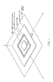
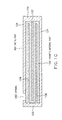
- FIG. 1 is a perspective view of a wireless power transmission system provided with a leakage preventing device of an electromagnetic wave according to a first embodiment.
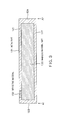
- FIG. 2 shows a sectional view of the leakage preventing device taken along an A1-A2 line of FIG. 1 . Sectional views taken along those other than the A1-A2 line also are the same as FIG. 2 .
- This leakage preventing device is provided with respect to an electric power transmission device (power transmitting device or power receiving device) of the wireless power transmission system, and suppresses an electromagnetic wave from leaking to a periphery of the electric power transmission device on transmitting electric power.
- the electric power transmission device having the leakage preventing device arranged therefor may be a power transmitting device or power receiving device, and herein a case is shown of arranging in a power transmitting device.
- a power transmitting device 201 is arranged on a ground plane (mounting surface) 301.
- the power transmitting device 201 wirelessly transmits the electric power to a power receiving device (refer to FIG. 5 ) arranged so as to be opposed thereto using the electromagnetic wave.
- the power transmitting device 201 has a power transmitting coil and the power receiving device has a power receiving coil, and the electric power is transmitted between the power transmitting coil and the power receiving coil due to magnetic coupling.
- the ground plane 301 may be a finite conductive ground plane or the ground surface.
- the leakage preventing device is arranged on or above the ground plane 301 with respect to the power transmitting device 201.
- the leakage preventing device as a whole has a shape surrounding the periphery of the power transmitting device 201. All or a part of the leakage preventing device may be embedded in the ground.
- This leakage preventing device functions to prevent the electromagnetic wave from leaking to the periphery (e.g., in a direction parallel to an xy-axis plain) on transmitting the electric power between the power transmitting device and the power receiving device.
- the ground plane 301 is a conductor plate
- arrangement of the leakage preventing device on or above the conductor plate makes it possible to, besides a leakage preventing function above a land surface, prevent the electromagnetic wave from leaking down from a ground surface side.
- the conductor plate may be not only a flat plate but also a netted, linear, or spiral shape. Further, the conductor plate and the leakage preventing device may be integrally formed.
- the leakage preventing device includes a metal part (metal pipe) 101 arranged to surround the power transmitting device, and a magnetic material part 103 arrnaged within the metal pipe 101 along a circumferential direction of the metal pipe 101.
- the metal pipe 101 has an opening 102 formed along the circumferential direction of the metal pipe 101.
- a general shape of the leakage preventing device seen from a z-axis direction that is, a shape of the metal pipe 101 seen from the z-axis direction is a rectangle ring.
- ring shapes of the metal pipe 101, opening 102, and magnetic material part 103 are not limited to a rectangle, but may be other shapes such as a polygon, circle, ellipse and the like.
- the metal pipe 101 has a front side part 121, back side part 122, inward lateral side part 123, and outward lateral side part 124.
- the back side part 122 is opposed to the front side part 121 and is still opposed to the power receiving device (a second electric power transmission device) across the front side part 121.
- the inward lateral side part 123 is formed between one end of the front side part 121 and one end of the back side part 122 and surrounds a periphery of the power transmitting device 201.
- the outward lateral side part 124 is formed between the other end of the front side part 121 and the other end of the back side part 122 and surrounds the periphery of the power transmitting device 201 across the inward lateral side part 123.
- the opening 102 is formed on the front side part 121.
- the metal pipe 101 has the magnetic material part 103 as a flat plate magnetic material arranged inside thereof.
- the magnetic material part 103 is formed along the circumferential direction of the pipe to fill an inside the pipe.
- a length (width) between the inward lateral side part 123 and the outward lateral side part 124 is larger than a length (thickness) between the front side part 121 and the back side part 122.
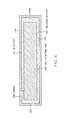
- the opening 102 may have a dielectric material 151 formed therein as shown in FIG. 3 .
- the dielectric material 151 can protect an inside of the metal pipe 101.
- the whole of the device that is, the whole of the metal pipe 101 may be covered with the dielectric material 161. This can serve as a cover to protect this device.
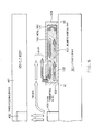
- FIG. 5 shows an operation in a case where electric power is transmitted from the power transmitting device 201 arranged on the ground surface 301 to a power receiving device 402 of a vehicle (vehicle body) 401.
- the opening 102 is formed at a position offset from a left end of a pipe space in FIG. 2 , but in an example of FIG. 5 the opening is formed at the left end.
- a part of the electromagnetic wave leaks out to the periphery.
- the ground surface 301 and the vehicle 401 operate as a kind of parallel plate, and the electromagnetic wave (TEM wave) having an electric field component in a vertical direction to the ground surface 301 is propagated in parallel to the ground surface 301 and leaks out to a space around the periphery.
- This part of the electromagnetic wave is coupled with the opening of the leakage preventing device to enter into the metal pipe.
- the entering electromagnetic wave propagates in the magnetic material 103.
- a propagation path of an electromagnetic wave entering from the opening, propagating through the magnetic material part 103, and reflecting on an inner wall of the outward lateral side part 124 is defined as D1.
- a propagation path for the electromagnetic wave which is reflected on the outward lateral side part 124, propagated through the magnetic material part 103, and reradiated from the opening is defined as D2.
- the entire propagation path of D1 plus D2 is defined as T1. Lengths of the propagation paths D1 and D2 are equal to each other.
- the length of the propagation path D1 is approximately 1/4 of a wavelength in pipe with taking account of an wavelength shortening effect due to relative permeability of the magnetic material part 103, the electromagnetic wave reradiated from the opening is deviated in phase by 180 degrees from the electromagnetic wave leaked out from the power transmitting device. Therefore, the phases are canceled with each other as shown in FIG. 5 . This allows the leaked electromagnetic wave to decrease to obtain a high transmission efficiency.
- a width in pipe W1 (refer to FIG. 6 ) is 2.4 m around.
- the width in pipe W1 is considered to be substantially equal to the length of the propagation path D1.
- the length of the propagation path D1 (or width in pipe W1) may be equal to or more than 1/8 and equal to or less than 3/8 of the wavelength in pipe. More generally, the entire propagation path in the pipe from entering the opening to being reradiated may be equal to or more than 1/4 and equal to or less than 3/4 of the wavelength in pipe.
- the longest path of these paths may only satisfy the above wavelength condition.
- the longest path is the latter path, that is, the path with being propagated to the outward lateral side part 124, reflected on the outward lateral side part 124, and reradiated from the opening.
- the magnetic material part is arranged so as to entirely fill the inside of the pipe, but as show in FIG. 7(A) and FIG. 7(B) , magnetic material parts 103A and 103B may be arranged so as to partially leave a gap in the pipe. Further, as show in FIG. 7(C) , a dielectric material 172 or the like may be introduced into the pipe to cover the whole of a magnetic material part 103C with the dielectric material 172.
- the leakage preventing device shown in FIG. 1 may be formed physically into one body, or may be, as shown in FIG. 8 , formed by dividing the leakage preventing device into a plurality of blocks 11, 12, 13, 14, 15, 16, 17, and 18 and arranging these blocks. No gap preferably exists between the neighboring blocks, but there is no problem so long as a gap may be sufficient small as much as about 1/100 of the wavelength.
- surfaces of the neighboring blocks to be coupled to each other may be covered with the dielectric material. However, the relevant surface must not be covered with metal.
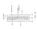
- FIG. 9 is a sectional view showing a structure example of a leakage preventing device of an electromagnetic wave according to the second embodiment. An appearance of the leakage preventing device of this embodiment is the same as that of FIG. 1 , and FIG. 9 shows the sectional view corresponding to that taken along A1-A2 line of FIG. 1 .
- the metal part (metal pipe) 101 has a metal plate 125 arranged therein along the circumferential direction. One end of the metal plate 125 is coupled with near the center of an inner wall of the inward lateral side part 123 and the other end thereof is free.
- the metal plate 125 defines a meandering path in the pipe which is turned back between the inward lateral side part and the outward lateral side part.
- a magnetic material part 113 is formed so as to fill the meandering path to result in having a folded structure.
- the magnetic material part 113 is formed along the circumferential direction of the pipe similarly to the first embodiment.
- the meandering path formed in the pipe allows the device to be reduced in size or in area.
- a propagation path T11 is a path for the electromagnetic wave which enters from the opening 102, is propagated in the pipe, and is reradiated from the opening 102.
- a length of the propagation path T11 is preferably about 1/2 of the wavelength in pipe, and may be equal to or more than 1/4 and equal to or less than 3/4 of the wavelength in pipe.
- a total length of a length from the opening 102 to one of the inward lateral side part 123 and the outward lateral side part 124 (outward lateral side part 124 in the example of FIG. 9 ) and a length between the inward lateral side part 123 and the outward lateral side part 124 may be equal to or more than 1/8 and equal to or less than 3/8 of the wavelength in pipe.
- the other end of the metal plate 125 may be coupled with the inner wall of the outward lateral side part 124 to make one end of the metal plate 125 free.
- both one end and the other end of the metal plate 125 may be made free and the metal plate 125 may be embedded inside the magnetic material part 113.
- FIG. 10 is a sectional view showing another structure example of the leakage preventing device according to the second embodiment. Difference in the structure from FIG. 9 is that the number of the metal plates arranged in the pipe is increased from one to three. One ends of each of metal plates 128 and 126 are coupled with the inward lateral side part 123 and the other ends thereof are free. One end of a metal plate 127 is coupled with the outward lateral side part 124, and the other end thereof is free. These metal plates define a meandering path increased in the folding number compared with the case in FIG. 9 .
- the magnetic material part 133 is formed so as to fill the meandering path to result in having a folded structure.
- a total length of a length from the opening 102 to one of the inward lateral side part 123 and the outward lateral side part 124 (outward lateral side part 124 in the example of FIG. 9 ) and three times a length between the inward lateral side part 123 and the outward lateral side part 124 may be equal to or more than 1/8 and equal to or less than 3/8 of the wavelength in pipe.
- a total length of a length from the opening 102 to one of the inward lateral side part 123 and the outward lateral side part 124, and N times a length between the inward lateral side part 123 and the outward lateral side part 124 may be equal to or more than 1/8 and equal to or less than 3/8 of the wavelength in pipe.
- the structure in FIG. 10 is adopted to allow the reduction in size as compared with the structure in FIG. 9 .
- FIG. 11 is a sectional view showing still another structure example of the leakage preventing device according to the second embodiment.
- a metal pipe (metal part) 701 includes a front side part 711, back side part 712, inward lateral side part 713, and outward lateral side part 714.
- the metal pipe 701 has metal plates 721, 722, 723, and 724 arranged therein. One ends of each of the metal plates 721 and 723 are coupled with an inner wall of the front side part 711, and the other ends thereof are free. One ends of each of the metal plates 722 and 724 are coupled with an inner wall of the back side part 712, and the other ends thereof are free.
- These metal plates define a meandering path in the pipe which is turned back plural times between the front side part and the back side part.
- a magnetic material part 703 is formed so as the fill the meandering path to result in having a folding structure. This structure also allows the reduction in size of the device.
- FIG. 12 is a perspective view of a wireless power transmission system provided with a leakage preventing device of an electromagnetic wave according to a third embodiment.
- FIG. 13 is a sectional view taken along B1-B22 line of FIG. 12 .
- the leakage preventing device is arranged on the ground plane (mounting surface) 301 to generally have a flat shape.
- a part of the device is embedded in the ground to have generally a shape extended in the z-axis direction.
- the portion embedded in the ground is represented with a dotted line.
- a metal part (metal pipe) 501 has a structure like a ring which is obtained by coupling both ends of a metal square tube to each other.
- the metal pipe 501 has, as shown in FIG. 13 , a front side part 511, back side part 512, inward lateral side part 513, and outward lateral side part 514.
- the front side part 511 has an opening 502 formed thereon along a circumferential direction of the metal pipe 501.
- the magnetic material part 503 is formed in the metal pipe 501 along the circumferential direction of the metal pipe 501.
- the magnetic material part 503 is formed so as to entirely fill the inside of the pipe.
- a space or dielectric material may exist in a part of the inside of the pipe.
- a propagation path T21 is a path for the electromagnetic wave which enters in the opening 502, is propagated in the pipe, and is reradiated.
- a length of the propagation path T21 is preferably about 1/2 of the wavelength in pipe, and may be equal to or more than 1/4 and equal to or less than 3/4 of the wavelength in pipe.
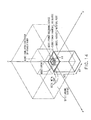
- FIG. 14 shows a state where the leakage preventing device (metal part 601, opening 602, magnetic material part 603) according to the third embodiment is arranged with respect to a power transmitting device 620.
- the power transmitting device 620 includes the power transmitting coil, electric power generating unit, and the like.
- the power transmitting device 620 is expressed in a picture of the power transmitting coil in the figure. Assuming a situation where a power receiving device 631 is arranged in the vehicle body, and the vehicle body is parked such that the power receiving device 631 faces the power transmitting device.
- the vehicle body is expressed as simulated conductor 630 of the vehicle body.
- the electric power transmitted from the power transmitting device 620 to the power receiving device 631 is accumulated in a storage battery in the vehicle body, for example.
- the magnetic material part has a width of 10 cm (X1 in FIG. 14 ), a 1.4 m on a side (X2 in FIG. 14 ) base, and a thickness of 2.4 m (X3 in FIG. 14 ).
- an electromagnetic wave leakage preventing effect according to this device is analyzed by an electromagnetic field simulator with a frequency of 100 kHz.
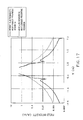
- FIG. 16 shows a magnetic field distribution in the vicinity of the power transmitting device 620 which is obtained by simulation using a configuration of FIG. 14 .
- FIG. 15 shows a magnetic field distribution in the vicinity of the power transmitting device in a case of simulation using a configuration in which the leakage preventing device is removed from the configuration of FIG. 14 .
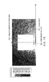
- FIG. 17 shows each of the distributions shown in FIG. 16 and FIG. 15 in a graphic form.
- a horizontal axis represents a position in the Y-axis direction, and a vertical axis represents field intensity.
- a position having a value 0 on the Y-axis is defined as an arrangement position for the power transmitting device. In comparison of these graphs with each other, it can be confirmed that the electromagnetic wave leaking to the periphery of the power transmitting device considerably decreases.
Landscapes
- Engineering & Computer Science (AREA)
- Power Engineering (AREA)
- Transportation (AREA)
- Mechanical Engineering (AREA)
- Computer Networks & Wireless Communication (AREA)
- Physics & Mathematics (AREA)
- Electromagnetism (AREA)
- Microelectronics & Electronic Packaging (AREA)
- Shielding Devices Or Components To Electric Or Magnetic Fields (AREA)
- Electric Propulsion And Braking For Vehicles (AREA)
Applications Claiming Priority (1)
| Application Number | Priority Date | Filing Date | Title |
|---|---|---|---|
| JP2013033737A JP2014165997A (ja) | 2013-02-22 | 2013-02-22 | 電磁波漏洩防止装置および無線電力伝送システム |
Publications (1)
| Publication Number | Publication Date |
|---|---|
| EP2769873A1 true EP2769873A1 (fr) | 2014-08-27 |
Family
ID=50238099
Family Applications (1)
| Application Number | Title | Priority Date | Filing Date |
|---|---|---|---|
| EP14155597.9A Withdrawn EP2769873A1 (fr) | 2013-02-22 | 2014-02-18 | Dispositif de prévention de fuite d'ondes électromagnétiques et système de transmission de puissance sans fil |
Country Status (4)
| Country | Link |
|---|---|
| US (1) | US9730368B2 (fr) |
| EP (1) | EP2769873A1 (fr) |
| JP (1) | JP2014165997A (fr) |
| CN (1) | CN104010479A (fr) |
Families Citing this family (2)
| Publication number | Priority date | Publication date | Assignee | Title |
|---|---|---|---|---|
| JP6414017B2 (ja) * | 2015-10-28 | 2018-10-31 | 三菱電機株式会社 | 電磁波減衰構造体及び電磁シールド構造体 |
| US11955711B2 (en) | 2019-03-14 | 2024-04-09 | Huawei Technologies Co., Ltd. | Redirecting structure for electromagnetic waves |
Citations (6)
| Publication number | Priority date | Publication date | Assignee | Title |
|---|---|---|---|---|
| JPS57136197U (fr) * | 1981-02-20 | 1982-08-25 | ||
| US4701731A (en) * | 1986-04-23 | 1987-10-20 | Hughes Aircraft Company | Pivotable conical joint for waveguides |
| JP2007013311A (ja) * | 2005-06-28 | 2007-01-18 | Murata Mfg Co Ltd | アンテナモジュールおよび無線装置 |
| US20100073248A1 (en) * | 2006-11-08 | 2010-03-25 | Eduardo Motta Cruz | Flat antenna ground plane supporting body including quarter-wave traps |
| EP2515314A1 (fr) * | 2009-12-17 | 2012-10-24 | Toyota Jidosha Kabushiki Kaisha | Blindage et véhicule équipé d'un tel blindage |
| WO2012144658A2 (fr) * | 2011-04-22 | 2012-10-26 | Yazaki Corporation | Système d'alimentation en énergie sans contact du type à résonance, appareil côté transmission d'énergie et appareil de charge embarqué de système d'alimentation en énergie sans contact du type à résonance |
Family Cites Families (6)
| Publication number | Priority date | Publication date | Assignee | Title |
|---|---|---|---|---|
| JP4865451B2 (ja) | 2006-08-24 | 2012-02-01 | 三菱重工業株式会社 | 受電装置及び送電装置並びに車両 |
| US8952857B2 (en) * | 2008-08-29 | 2015-02-10 | Arizona Board Of Regents, A Body Corporate Of The State Of Arizona Acting For And On Behalf Of Arizona State University | Antennas with broadband operating bandwidths |
| KR101040662B1 (ko) * | 2009-04-06 | 2011-06-13 | 한국과학기술원 | 전기자동차용 초박형 급전장치와 집전장치 |
| JP5490046B2 (ja) | 2011-03-22 | 2014-05-14 | 株式会社東芝 | 伝送装置 |
| JP6148501B2 (ja) | 2013-03-01 | 2017-06-14 | 株式会社東芝 | 送電システム |
| JP2014241673A (ja) | 2013-06-11 | 2014-12-25 | 株式会社東芝 | 電磁波漏洩防止装置 |
-
2013
- 2013-02-22 JP JP2013033737A patent/JP2014165997A/ja active Pending
-
2014
- 2014-02-18 EP EP14155597.9A patent/EP2769873A1/fr not_active Withdrawn
- 2014-02-19 US US14/183,808 patent/US9730368B2/en not_active Expired - Fee Related
- 2014-02-20 CN CN201410057362.4A patent/CN104010479A/zh active Pending
Patent Citations (6)
| Publication number | Priority date | Publication date | Assignee | Title |
|---|---|---|---|---|
| JPS57136197U (fr) * | 1981-02-20 | 1982-08-25 | ||
| US4701731A (en) * | 1986-04-23 | 1987-10-20 | Hughes Aircraft Company | Pivotable conical joint for waveguides |
| JP2007013311A (ja) * | 2005-06-28 | 2007-01-18 | Murata Mfg Co Ltd | アンテナモジュールおよび無線装置 |
| US20100073248A1 (en) * | 2006-11-08 | 2010-03-25 | Eduardo Motta Cruz | Flat antenna ground plane supporting body including quarter-wave traps |
| EP2515314A1 (fr) * | 2009-12-17 | 2012-10-24 | Toyota Jidosha Kabushiki Kaisha | Blindage et véhicule équipé d'un tel blindage |
| WO2012144658A2 (fr) * | 2011-04-22 | 2012-10-26 | Yazaki Corporation | Système d'alimentation en énergie sans contact du type à résonance, appareil côté transmission d'énergie et appareil de charge embarqué de système d'alimentation en énergie sans contact du type à résonance |
Also Published As
| Publication number | Publication date |
|---|---|
| CN104010479A (zh) | 2014-08-27 |
| US9730368B2 (en) | 2017-08-08 |
| US20140239730A1 (en) | 2014-08-28 |
| JP2014165997A (ja) | 2014-09-08 |
Similar Documents
| Publication | Publication Date | Title |
|---|---|---|
| CN104487862B (zh) | 雷达装置 | |
| US9070962B2 (en) | Surface communication device | |
| US8149180B2 (en) | Antenna with resonator having a filtering coating and system including such antenna | |
| JP5667019B2 (ja) | 無線電力伝送装置およびその方法 | |
| JP6157498B2 (ja) | 共振素子を用いた回折格子を有する反射防止被覆構造 | |
| US9577477B2 (en) | Power transmission apparatus and method, and resonance device used therein | |
| CN104137326A (zh) | 在天线装置和无线电通信装置之间的连接结构 | |
| CN114824747A (zh) | 带有波瓣抑制的波导件 | |
| US9730368B2 (en) | Leakage preventing device of electromagnetic wave and wireless power transmission system | |
| JP2013207161A (ja) | 高周波シールド構造 | |
| US20150008994A1 (en) | Interface apparatus | |
| ES2763108T3 (es) | Desfase de reflexiones de señales de ondas que se propagan por una superficie | |
| US9853501B2 (en) | Electromagnetic wave transmission sheet and electromagnetic wave transmission device | |
| JP2017229231A (ja) | 電磁波漏洩防止装置および無線電力伝送システム | |
| JP5906777B2 (ja) | 電子棚札システム | |
| JP5985112B2 (ja) | 導波管装置 | |
| KR100834608B1 (ko) | 수평편파 특성의 광대역 누설동축케이블 | |
| JP6200256B2 (ja) | 放電ランプ装置 | |
| CN104078735A (zh) | 利用阶梯部和阻挡部的等离子体波导 | |
| JP5981466B2 (ja) | 平面伝送線路導波管変換器 | |
| JPWO2018020550A1 (ja) | リフレクトアレーアンテナ | |
| US12230857B2 (en) | Radar waveguide and choke assembly | |
| JP2014154960A (ja) | アンテナ装置用一次放射器、およびアンテナ装置 | |
| JP2013070366A (ja) | 空中線 | |
| JPH04186903A (ja) | 導波管スロット・アンテナ |
Legal Events
| Date | Code | Title | Description |
|---|---|---|---|
| PUAI | Public reference made under article 153(3) epc to a published international application that has entered the european phase |
Free format text: ORIGINAL CODE: 0009012 |
|
| 17P | Request for examination filed |
Effective date: 20140218 |
|
| AK | Designated contracting states |
Kind code of ref document: A1 Designated state(s): AL AT BE BG CH CY CZ DE DK EE ES FI FR GB GR HR HU IE IS IT LI LT LU LV MC MK MT NL NO PL PT RO RS SE SI SK SM TR |
|
| AX | Request for extension of the european patent |
Extension state: BA ME |
|
| STAA | Information on the status of an ep patent application or granted ep patent |
Free format text: STATUS: EXAMINATION IS IN PROGRESS |
|
| 17Q | First examination report despatched |
Effective date: 20170126 |
|
| GRAP | Despatch of communication of intention to grant a patent |
Free format text: ORIGINAL CODE: EPIDOSNIGR1 |
|
| STAA | Information on the status of an ep patent application or granted ep patent |
Free format text: STATUS: GRANT OF PATENT IS INTENDED |
|
| RIC1 | Information provided on ipc code assigned before grant |
Ipc: B60L 11/18 20060101AFI20180926BHEP Ipc: H02J 50/70 20160101ALI20180926BHEP Ipc: H01F 38/14 20060101ALI20180926BHEP Ipc: H02J 50/10 20160101ALI20180926BHEP Ipc: H01Q 1/52 20060101ALI20180926BHEP Ipc: H02J 7/02 20060101ALI20180926BHEP Ipc: H01F 27/36 20060101ALI20180926BHEP Ipc: H05K 9/00 20060101ALI20180926BHEP |
|
| INTG | Intention to grant announced |
Effective date: 20181017 |
|
| RIC1 | Information provided on ipc code assigned before grant |
Ipc: H01F 38/14 20060101ALI20180926BHEP Ipc: B60L 11/18 20060101AFI20180926BHEP Ipc: H01F 27/36 20060101ALI20180926BHEP Ipc: H02J 50/70 20160101ALI20180926BHEP Ipc: H02J 7/02 20160101ALI20180926BHEP Ipc: H01Q 1/52 20060101ALI20180926BHEP Ipc: H02J 50/10 20160101ALI20180926BHEP Ipc: H05K 9/00 20060101ALI20180926BHEP |
|
| STAA | Information on the status of an ep patent application or granted ep patent |
Free format text: STATUS: THE APPLICATION IS DEEMED TO BE WITHDRAWN |
|
| 18D | Application deemed to be withdrawn |
Effective date: 20190228 |