EP2769914B1 - Direction d'essieu compact de train d'atterrissage principal - Google Patents
Direction d'essieu compact de train d'atterrissage principal Download PDFInfo
- Publication number
- EP2769914B1 EP2769914B1 EP14156248.8A EP14156248A EP2769914B1 EP 2769914 B1 EP2769914 B1 EP 2769914B1 EP 14156248 A EP14156248 A EP 14156248A EP 2769914 B1 EP2769914 B1 EP 2769914B1
- Authority
- EP
- European Patent Office
- Prior art keywords
- steering
- control link
- landing gear
- axle
- rack
- Prior art date
- Legal status (The legal status is an assumption and is not a legal conclusion. Google has not performed a legal analysis and makes no representation as to the accuracy of the status listed.)
- Active
Links
Images



Classifications
-
- B—PERFORMING OPERATIONS; TRANSPORTING
- B64—AIRCRAFT; AVIATION; COSMONAUTICS
- B64C—AEROPLANES; HELICOPTERS
- B64C25/00—Alighting gear
- B64C25/32—Alighting gear characterised by elements which contact the ground or similar surface
- B64C25/50—Steerable undercarriages; Shimmy-damping
-
- B—PERFORMING OPERATIONS; TRANSPORTING
- B64—AIRCRAFT; AVIATION; COSMONAUTICS
- B64C—AEROPLANES; HELICOPTERS
- B64C25/00—Alighting gear
- B64C25/32—Alighting gear characterised by elements which contact the ground or similar surface
- B64C25/34—Alighting gear characterised by elements which contact the ground or similar surface wheeled type, e.g. multi-wheeled bogies
-
- B—PERFORMING OPERATIONS; TRANSPORTING
- B64—AIRCRAFT; AVIATION; COSMONAUTICS
- B64C—AEROPLANES; HELICOPTERS
- B64C25/00—Alighting gear
- B64C25/32—Alighting gear characterised by elements which contact the ground or similar surface
- B64C25/34—Alighting gear characterised by elements which contact the ground or similar surface wheeled type, e.g. multi-wheeled bogies
- B64C2025/345—Multi-wheel bogies having one or more steering axes
Definitions
- the described subject matter relates generally to aircraft landing gears, and more specifically to steering systems for aircraft landing gears.
- Landing gear for large aircraft have traditionally employed a telescoping shock-absorbing strut with a multi-wheel truck attached. Such structures can effectively handle and react the various forces seen during taxiing.
- main landing gears with six wheeled or greater bogie beam configurations have utilized a steerable aft and/or forward axle.
- Most common approaches to provide for axle steering utilizing hydraulic actuators that directly or indirectly push or pull the axle to the desired steering angle.
- Traditional push-pull steering systems are sized to produce enough steering torque at the minimum moment arm. As a result, the available steering torque is higher than required for most of the steerable range.
- EP 2 366 623 A2 discloses a steering arrangement according to the preamble of claim 1.
- the invention provides a steering arrangement as claimed in claim 1.
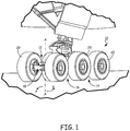
- FIG. 1 shows an example main landing gear system 10 for an aircraft.
- main landing gear system 10 is shown as having a three-axle bogie beam configuration with six wheels.
- Main landing gear system 10 generally includes bogie beam 12, fixed forward axle 14, fixed center axle 16, and aft axle 18.
- Each axle 14, 16, 18 is mounted transversely to bogie beam 12, and each includes two wheels 20 on either side of bogie beam 12.
- aft axle 18 is steerable by pivoting or rotating axle 18 about axis A.
- the steering system can be used to control one or more axles mounted to a bogie-style landing gear system, such as, but not limited to, a six-wheel landing gear system having three two-wheel axles. While this example is described with respect to forward axle 14 and center axle 16 being fixed with respect to the bogie beam 12, it will be appreciated that the described subject matter can be readily adapted to additionally and/or alternatively fix aft or other axles. While this example is described with respect to aft axle 18 being steerable/pivotable with respect to the bogie beam 12, it will be appreciated that the described subject matter can be readily adapted to additionally and/or alternatively steer/pivot forward, center or other axles. For example, axle steering arrangements may be provided to steer multiple pivotable axles such as a forward axle and an aft axle on the same bogie beam.
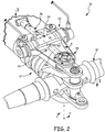
- FIG. 2 is a perspective view of an aft portion of main landing gear system 10.
- FIG. 2 shows axle steering arrangement 30 which is adapted to control steering of aft axle 18 about bogie beam 12.
- FIG. 2 also shows linear actuator assembly 34, locking mechanism 36, actuator compartment 38, control link 40, cover 41, control link actuator end 42, and control link axle end 44.
- Main landing gear system 10 includes axle steering arrangement 30 mounted to bogie beam 12.
- axle steering arrangement 30 is operative to control steering of aft axle 18 which is pivotable about common axis A in clockwise and counterclockwise directions P.
- Common axis A is generally perpendicular to, and extends through both bogie beam 12 and aft axle 18.
- Axle steering arrangement 30 generally includes linear actuator assembly 34, locking mechanism 36, and control link 40.
- Linear actuator assembly 34 is mounted transversely to bogie beam 12, and generally parallel to a neutral (e.g., 0°) steering position of aft axle 18.
- Locking mechanism 36 can be provided to lock aft axle 18 into a neutral or other steering position to prevent inadvertent steering inputs, outputs, or other movements.
- One or more elements of axle steering arrangement 30 can be retained in actuator compartment 38, which may be secured on, or formed directly into a recess in bogie beam 12.
- actuator compartment 38 comprises an opening formed as part of actuator housing 45 (shown in FIGS. 3A-3C ) which houses actuator assembly 34 and control link 40. Cover 41 (partially cut away for clarity) can be placed over actuator compartment 38 to protect moving parts such as those contained in actuator assembly 34 and control link 40 from FOD and dirt.
- Control link 40 includes actuator end 42 rotatably engaged with actuator assembly 34, and axle end 44 engaged with aft axle 18. Extendable control link 40 allows radial displacement of the control link 40, thereby allowing axle steering arrangement 30 to stroke to the desired position as defined by linear actuator assembly 34.
- linear actuator assembly 34 includes one or more pistons or other elements which can be actuated transversely relative to bogie beam 12. This translates actuator end 42 of control link 40 also in a transverse direction. In turn, lateral translation of actuator end 42 pivots axle end 44 in direction P and imparts a corresponding steering or pivoting motion to aft axle 18 about axis A.
- control link 40 can be configured to longitudinally extend and retract as actuator end 42 is moved laterally to either side of bogie beam 12.
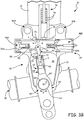
- FIGS. 3A-3C taken through line 3-3 of FIG. 2 , show a sectional view of main landing gear system 10 in three different steering configurations.
- FIG. 3A shows main landing gear system 10 with axle steering arrangement 30 and aft axle 18 in a neutral steering position relative to bogie beam 12.
- FIGS. 3B and 3C respectively show main landing gear system 10 with aft axle 18 in a clockwise and counterclockwise steering position.
- FIGS. 3A-3C taken through line 3-3 of FIG. 2 , show a sectional view of main landing gear system 10 in three different steering configurations.
- FIG. 3A shows main landing gear system 10 with axle steering arrangement 30 and aft axle 18 in a neutral steering position relative to bogie beam 12.
- FIGS. 3B and 3C respectively show main landing gear system 10 with aft axle 18 in a clockwise and counterclockwise steering position.
- 3A-3C also include linear actuator assembly 34, locking mechanism 36, actuator compartment 38, control link 40, actuator end 42, axle end 44, actuator housing 45, beam attachment regions 46A, 46B, actuators 48A, 48B, steering rack 50, actuator heads 52A, 52B, first control link bore 54, control link arm 56, rack pin 58, control link body 60, axle pivot pin 62, second control link bore 64, arm piston portion 66, control link piston chamber 68, control link sleeve outer stops 70, lock plunger 74, lock recess 76, lock spring 78, and axle attachment region 80.
- linear actuator assembly 34 can include actuator housing 45 mounted to bogie beam 12.
- actuator housing 45 is secured to bogie beam 12 at beam attachment regions 46A, 46B such that it is retained substantially transversely thereto.
- two transversely opposed actuators (e.g., hydraulic pistons) 48A, 48B are mounted to steering rack 50.
- Actuators 48A, 48B are configured to laterally translate rack 50 in direction T by controlling differential hydraulic or other fluid pressures applied to actuator heads 52A, 52B.
- actuators 48A, 48B can be operated by other means such as electromotive forces applied in and around steering rack 50.
- Control link 40 which can be disposed in actuator compartment 38, operatively connects steering rack 50 to pivotable or steerable aft axle 18.
- control link 40 includes actuator end 42 secured to actuator assembly 34, and axle end 44 in pivotable engagement with axle 18.
- actuator end 42 is secured via first control link bore 54 to steering rack 50, which is in pivotable engagement with control link arm 56.
- First control link bore 54 can be engaged with control link arm 56, for example, via rack pin 58 or the like.
- FIGS. 3A-3C show control link body 60 with axle pivot pin 62 proximate to a control link pivot point and retained in second control link bore 64 of control link 40.
- Control link 40 converts linear motion of steering rack 50 into a pivoting or rotational motion of axle 18 in direction P about a pivot point such as common axis A. Since steering rack 50 is configured to move transversely, but not longitudinally, relative to bogie beam 12, the distance between control link bore 54 and axle pivot pin 62 necessarily varies based on the applied steering inputs and resulting outputs. As such, control link 40 is configured to extend and retract in longitudinal direction L. Examples of steering operation are shown in FIGS. 3B and 3C .
- actuator assembly 34 is positioned with steering rack 50 located approximately at a midpoint of the actuation range, generally halfway between the transverse extremes shown in FIGS. 3B and 3C .
- control link arm 56 and rack pin 58 are positioned such that the entirety of control link 40 generally overlies the central longitudinal axis of bogie beam 12 when aft axle 18 is oriented in a neutral steering position.
- this will be referred to as about 50% stroke on a 0% to 100% scale.
- the configuration of FIG. 3A can be described as 0% stroke on a scale of -100% to + 100%.
- FIGS. 3B and 3C respectively show an example of how to operate steering arrangement 30 so that aft axle 18 is rotated counterclockwise and clockwise relative to the neutral steering configuration of FIG. 3A .
- differential pressures are applied to actuator heads 52A, 52B such that actuators 48A, 48B move leftward along direction T, causing actuator assembly 34 to approach 0% stroke.
- This causes steering rack 50 and control link arm 56 to also move leftward along direction T (via rack pin 58), relative to the longitudinal axis of bogie beam 12 and the forward direction of the aircraft.
- actuator end 42 of control link 40 is pulled leftward, causing axle end 44 to pivot counterclockwise in direction P about pivot pin 62 and common axis A.
- FIG. 3C operates in a similar manner, with differential pressures applied to move actuators 48A, 48B rightward such that actuator assembly 34 approaches 100% stroke, and causes axle end 44 to pivot clockwise in direction P around common axis A.
- control link 40 is configured to be extendable and retractable in a longitudinal direction L.
- a longitudinal dimension of control link 40 generally ranges between a first retracted length and a second extended length through a steering range of pivotable aft axle 18.
- a longitudinal dimension of extendable steering control link 40 is approximately equal to the first retracted length when pivotable landing gear aft axle 18 is oriented in or near a neutral steering position (as shown in FIG. 3A ).
- the neutral steering position corresponds to when steering rack 50 is positioned at or proximate the midpoint of an actuation range of actuator assembly 34.
- a longitudinal dimension of extendable control link 40 can be approximately equal to its second extended length when pivotable aft axle 18 is oriented in a maximum counterclockwise steering position (shown in FIG. 3B ) and/or a maximum clockwise steering position (shown in FIG. 3C ). These correspond to maximum counterclockwise and clockwise steering inputs respectively.
- axle steering arrangement 30 may not utilize absolutely all of the extendable range of control link 40 and/or all of the actuation range of actuator assembly 34.
- landing gear system 10 will invariably experience mechanical and thermal stresses during use.
- control link 40 and/or the other components of axle steering arrangement 30 can be designed with certain tolerances to accommodate expected operational conditions.
- control link 40 is shown as a telescoping link with two coaxially arranged longitudinal segments, arm 56 and body 60.
- Arm 56 can include piston portion 66 retained in piston chamber 68 of control link body 60.
- Piston chamber 68 can be, for example, an open chamber formed within control link body 60.
- Piston chamber 68 can contain a fluid such that piston portion 66 is engaged in any suitable manner such as hydraulically, pneumatically or the like, depending on environmental considerations.
- control link arm 56 In response to lateral steering motion of linear actuator assembly 34 (as shown in FIGS. 3B and 3C ), control link arm 56 is pulled away from control link body 60 such that piston portion 66 moves outward along direction L toward outer stops 70. This effectively lengthens control link 40. As the steering input is returned toward a neutral position (shown in FIG. 3A ), control link arm 56 is pushed such that piston portion 66 moves away from outer stops 70 to effectively shorten control link 40.
- FIGS. 3A-3C also illustrate an example optional locking mechanism 36.
- optional locking mechanism 36 is of the hydraulically actuated type attached to actuator housing 45.
- plunger or pin 74 is operable to engage recess 76 formed in steering rack 50.
- Pin 74 can be biased with a resilient element such as spring 78 to automatically lock and maintain a lateral position of steering rack 50 in the absence of hydraulic pressure sufficient to retract plunger 74.
- locking mechanism 36 maintains steering rack 50 proximate a midpoint of the actuation range (shown in FIG. 3A ) corresponding to a neutral steering position. While shown as a hydraulically actuated locking mechanism, it will be appreciated that optional locking mechanism 36 can alternatively be other types of steering locks known in the art.
- One non-limiting alternative includes a plunger-type lock with a pin oriented normal to steering rack 50 and bogie beam 12.
- the locking pin is biased toward a rack or actuator recess using gravity and/or a resilient element.
- the bias force(s) are counteracted by a hydraulic, pneumatic, or solenoid activated actuator operable to lift the pin out of the recess.
- control link 40 can alternatively be configured as most any other type of longitudinally extendable element.
- control link 40 includes more than two longitudinal segments, with a corresponding number of interfaces (e.g., pistons and sleeves).
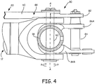
- FIG. 4 shows axle attachment region 80 with an example connection between bogie beam 12, aft axle 18, and control link 40 about common axis A.
- FIG. 4 also shows control link arm 60, upper lever arm 82, connection pin 84, and lower lever arms 86A, 86B.
- control link 40 As seen in FIG. 4 , aft end 44 of control link 40 is engaged with aft axle 18 at axle attachment region 80.
- upper lever arm 82 which can be secured to control link arm 60, extends aftward from the location of pivot pin 62.
- upper lever arm 82 can be an integral part of control link 40.
- a connection bolt or pin 84 connects upper lever arm 82 to corresponding lower lever arms 86A, 86B which also extend aftward from aft axle 18 and pivot pin 62.
- Connection pin 84 can be parallel to common axis A passing longitudinally through axle pivot pin 62.
- connection pin 84 As the pivoting motion is imparted to control link aft end 44 by steering rack 50 (shown in FIGS. 3A-3C ), this pivoting motion is transferred from upper lever arm 82 through connection pin 84 to lower lever arms 86A, 86B. This in turn transfers the pivoting or steering forces to axle 18 causing both control link 40 and aft axle 18 to pivot relative to bogie beam 12 about common axis A. While shown and described in the context of a single connection bolt or pin 84, it will be appreciated that multiple connection bolts or pins can be used in its place.
- FIG. 5 shows axle attachment region 80 with an alternative connection between bogie beam 12, aft axle 18, and control link 40 about common axis A.
- FIG. 5 also shows control link arm 60, upper lever arm 82, connection pin 84, lower lever arms 86A, 86B, trail arms 90A, 90B, and axle diameter center line 92.
- FIG. 5 shows aft end 44 of control link 40 engaged with aft axle 18 at axle attachment region 80.
- control link arm 60 is engaged with aft axle 18 via pivot pin 62 passing through trail arms 90A, 90B.
- pivot pin 62 and common axis A are not coincident with axle diameter center line 92.
- trail arms 90A, 90B receive pivot pin 62 at a location longitudinally spaced apart from axle diameter center line 92. This has the effect of causing aft axle 18 to trail bogie beam 12 while still allowing aft axle 18 to pivot about common axis A. This results in a nonzero mechanical trail distance between common axis A and a ground contact point of wheels 20 (shown in FIG. 1 ).
- the ground contact point of wheels 20 is generally coincident with axle diameter line 92.
- control link aft end 44 As the pivoting motion of control link aft end 44 is transferred from upper lever arm 82 through connection pin 84 to lower lever arms 86A, 86B, pivoting or steering forces are still transmitted to axle 18, causing both control link 40 and aft axle 18 to pivot about common axis A.
- An increased mechanical trail distance can, in certain embodiments, improve directional stability of aft axle 18.
Landscapes
- Engineering & Computer Science (AREA)
- Mechanical Engineering (AREA)
- Aviation & Aerospace Engineering (AREA)
- Steering-Linkage Mechanisms And Four-Wheel Steering (AREA)
Claims (15)
- Dispositif de direction (30) pour un essieu de train d'atterrissage (18) pivotant, le dispositif de direction (30) comprenant :une crémaillère de direction (50) ;un ensemble actionneur linéaire (34) pouvant fonctionner pour translater latéralement la crémaillère de direction (50) ; etune liaison de commande de direction (40) comportant une extrémité d'actionneur (42) fixée à la crémaillère de direction (50), et une extrémité d'essieu (44) opposée à l'extrémité d'actionneur (42), l'extrémité d'essieu pouvant pivoter autour d'un point de pivotement de liaison de commande, caractérisé en ce que :
la liaison de commande de direction (40) est extensible longitudinalement de sorte qu'une dimension longitudinale de la liaison de commande de direction (40) se situe entre une première longueur rétractée et une seconde longueur étendue. - Dispositif de direction selon la revendication 1, comprenant en outre :
un axe de pivotement (62) reçu par l'extrémité d'essieu de liaison de commande (44) à proximité du point de pivotement de liaison de commande. - Dispositif de direction selon la revendication 1 ou 2, dans lequel la dimension longitudinale de la liaison de commande de direction (40) est approximativement égale à la première longueur rétractée lorsque la crémaillère de direction (50) est positionnée à un point médian d'une plage d'actionnement.
- Dispositif de direction selon une quelconque revendication précédente, dans lequel la dimension longitudinale de la liaison de commande de direction (40) est approximativement égale à la seconde longueur étendue lorsque la crémaillère de direction (50) est positionnée au niveau d'une entrée de direction maximale.
- Dispositif de direction selon une quelconque revendication précédente, dans lequel la liaison de commande de direction (40) est une liaison de commande télescopique comprenant un segment de bras venant en prise de manière coaxiale avec un segment de corps.
- Dispositif de direction selon la revendication 5, dans lequel le segment de bras vient en prise de manière pivotante avec la crémaillère de direction (50).
- Dispositif de direction selon la revendication 5 ou 6, dans lequel le segment de bras comporte une partie de piston (66) mobile longitudinalement à l'intérieur d'une chambre (68) disposée dans le segment de corps.
- Dispositif de direction selon une quelconque revendication précédente, comprenant en outre :
un mécanisme de verrouillage (36) fixé à un boîtier d'actionneur (45), le mécanisme de verrouillage (36) comportant au moins une broche (74) pouvant fonctionner pour venir en prise avec et maintenir une position latérale de la crémaillère de direction (50). - Dispositif de direction selon une quelconque revendication précédente, dans lequel l'ensemble actionneur (34) comprend une paire d'actionneurs opposés transversalement (48A,48B).
- Système de train d'atterrissage (10) comprenant :un balancier de bogie (12) ;un essieu de train d'atterrissage (18) monté de manière pivotante sur le balancier de bogie (12) ; etle dispositif de direction selon une quelconque revendication précédente : dans lequella crémaillère de direction (50) est fixée transversalement au balancier de bogie (12) et espacée longitudinalement de l'essieu de train d'atterrissage (18) ; et dans lequell'extrémité d'essieu de la liaison de commande de direction (40) vient en prise avec l'essieu de train d'atterrissage (18), la liaison de commande de direction (40) et l'essieu de train d'atterrissage (18) pouvant pivoter par rapport au balancier de bogie (12) autour du point de pivotement de liaison de commande.
- Système de train d'atterrissage selon la revendication 10, dans lequel la dimension longitudinale de la liaison de commande de direction (40) est comprise entre la première longueur rétractée et la seconde longueur étendue sur une plage de direction de l'essieu de train d'atterrissage (18) pivotant.
- Système de train d'atterrissage selon la revendication 11, dans lequel la dimension longitudinale de la liaison de commande de direction (40) est approximativement égale à la première longueur rétractée lorsque l'essieu de train d'atterrissage (18) est orienté dans une position de direction neutre, et/ou dans lequel, la dimension longitudinale de la liaison de commande de direction (40) est approximativement égale à la seconde longueur étendue lorsque l'essieu de train d'atterrissage (18) est orienté dans au moins l'une parmi : une position de direction maximale dans le sens des aiguilles d'une montre et une position de direction maximale dans le sens inverse des aiguilles d'une montre.
- Système de train d'atterrissage selon la revendication 10, 11 ou 12, comprenant en outre :un axe de pivotement (62) s'étendant à travers la liaison de commande de direction (40), l'essieu de train d'atterrissage (18) et le balancier de bogie (12) au niveau de l'axe commun ; ouau moins un bras de traînée (90A,90B) ; etun axe de pivotement (62) s'étendant à travers la liaison de commande de direction (40), l'au moins un bras de traînée (90A,90B) et le balancier de bogie (12) au niveau de l'axe commun ;dans lequel l'axe de pivotement (62) est à un emplacement espacé longitudinalement d'une ligne centrale de diamètre d'essieu (92).
- Système de train d'atterrissage selon l'une quelconque des revendications 10 à 13, comprenant en outre :un mécanisme de verrouillage (36) pouvant fonctionner pour venir en prise avec l'un ou plusieurs parmi : l'essieu de train d'atterrissage (18), la crémaillère de direction (50), l'ensemble actionneur linéaire (34) et la liaison de commande de direction (40), et verrouiller l'essieu de train d'atterrissage (18) contre les mouvements de direction intempestifs, et/ouune pluralité d'essieux de train d'atterrissage fixes (14, 16) montés sur le balancier de bogie (12) ;
dans lequel l'essieu de train d'atterrissage (18) monté de manière pivotante est disposé à l'arrière de la pluralité d'essieux de train d'atterrissage fixes (14, 16). - Système de train d'atterrissage selon l'une quelconque des revendications 10 à 14, dans lequel la liaison de commande de direction (40) est une liaison de commande télescopique comprenant un segment de bras venant en prise coaxialement avec un segment de corps, et dans lequel, éventuellement, le segment de bras vient en prise de manière pivotante avec la crémaillère de direction (50), et le segment de corps vient en prise de manière pivotante avec l'essieu de train d'atterrissage (18) et le balancier de bogie (12) autour de l'axe commun.
Applications Claiming Priority (1)
| Application Number | Priority Date | Filing Date | Title |
|---|---|---|---|
| US13/774,218 US9290265B2 (en) | 2013-02-22 | 2013-02-22 | Main landing gear compact axle steering |
Publications (3)
| Publication Number | Publication Date |
|---|---|
| EP2769914A2 EP2769914A2 (fr) | 2014-08-27 |
| EP2769914A3 EP2769914A3 (fr) | 2017-12-06 |
| EP2769914B1 true EP2769914B1 (fr) | 2020-10-28 |
Family
ID=50137586
Family Applications (1)
| Application Number | Title | Priority Date | Filing Date |
|---|---|---|---|
| EP14156248.8A Active EP2769914B1 (fr) | 2013-02-22 | 2014-02-21 | Direction d'essieu compact de train d'atterrissage principal |
Country Status (3)
| Country | Link |
|---|---|
| US (1) | US9290265B2 (fr) |
| EP (1) | EP2769914B1 (fr) |
| CA (1) | CA2841323C (fr) |
Families Citing this family (12)
| Publication number | Priority date | Publication date | Assignee | Title |
|---|---|---|---|---|
| GB2537860A (en) * | 2015-04-28 | 2016-11-02 | Airbus Operations Sas | Aircraft steering system |
| EP3135581B1 (fr) * | 2015-08-25 | 2018-03-21 | Safran Landing Systems UK Limited | Ensemble de train d'atterrissage d'avion |
| CA167756S (en) * | 2015-10-07 | 2018-01-02 | Starship Tech Oü | Delivery robot |
| EP3279084B1 (fr) * | 2016-08-05 | 2019-04-10 | Safran Landing Systems UK Limited | Ensemble de train d'atterrissage d'avion |
| US10479487B2 (en) * | 2017-01-18 | 2019-11-19 | Goodrich Corporation | Landing gear folding brace with locking actuator |
| USD821265S1 (en) | 2017-03-23 | 2018-06-26 | Starship Technologies Oü | Vehicle |
| WO2018215581A1 (fr) | 2017-05-26 | 2018-11-29 | Starship Technologies Oü | Batterie et système de permutation et/ou de charge d'une batterie d'un robot mobile |
| WO2019020407A1 (fr) | 2017-07-28 | 2019-01-31 | Starship Technologies Oü | Dispositif et système de livraison sécurisée de colis par un robot mobile |
| CN110576967A (zh) * | 2019-09-29 | 2019-12-17 | 中国直升机设计研究所 | 一种起落架回中装置 |
| CN115447764B (zh) * | 2022-10-13 | 2024-09-06 | 中国航空工业集团公司西安飞机设计研究所 | 一种提升转轮式起落架 |
| KR20240084326A (ko) | 2022-12-06 | 2024-06-13 | 현대자동차주식회사 | 랜딩 기어 시스템 |
| US12466581B2 (en) * | 2023-05-08 | 2025-11-11 | The Boeing Company | Chock for steering mechanism of an aircraft nose landing gear |
Family Cites Families (15)
| Publication number | Priority date | Publication date | Assignee | Title |
|---|---|---|---|---|
| GB560659A (en) * | 1941-10-31 | 1944-04-14 | Maclaren Undercarriage Company | Improved means for locking fluid pressure actuated jacks |
| GB697937A (en) * | 1951-06-22 | 1953-09-30 | Dowty Equipment Ltd | Improvements in self-centering means for aircraft castorable landing wheel mountings |
| US3643898A (en) | 1969-12-17 | 1972-02-22 | Us Federal Aviation Admin | Methods and mechanisms for steering truck wheel axles by a rotatable truck beam |
| US5242131A (en) * | 1992-04-08 | 1993-09-07 | The Boeing Company | Steerable landing gear |
| US6123292A (en) | 1994-03-17 | 2000-09-26 | The Boeing Company | Main landing gear having independent steering of each axle on multiple axle trucks |
| US5513821A (en) | 1994-03-29 | 1996-05-07 | The Boeing Company | Aircraft steering system and method for large aircraft having main landing gear steering during low taxi speed while nose gear is castored |
| US5595359A (en) * | 1994-11-22 | 1997-01-21 | The Boeing Company | Landing gear axle steering |
| US5743491A (en) | 1994-12-08 | 1998-04-28 | The Boeing Company | Very large aircraft landing gear having eight wheel truck |
| US5613651A (en) | 1994-12-08 | 1997-03-25 | The Boeing Company | Landing gear axle steering without walking beam |
| FR2805799B1 (fr) | 2000-03-02 | 2002-06-14 | Messier Dowty Sa | Atterisseur d'aeronef a axe de pivotement de jambe fortement deporte |
| US6671588B2 (en) | 2001-12-27 | 2003-12-30 | Toyota Jidosha Kabushiki Kaisha | System and method for controlling traveling direction of aircraft |
| US6641085B1 (en) | 2002-10-04 | 2003-11-04 | Triumph Brands, Inc. | Self-centering steering module |
| CA2570657A1 (fr) * | 2004-06-18 | 2006-07-06 | Goodrich Corporation | Train d'atterrissage dote d'un systeme d'orientation a blocage |
| WO2006071263A2 (fr) * | 2004-06-18 | 2006-07-06 | Goodrich Corporation | Train d'atterrissage articule escamotable |
| US8668163B2 (en) * | 2010-03-05 | 2014-03-11 | Goodrich Corporation | Rack and pinion landing gear steering system |
-
2013
- 2013-02-22 US US13/774,218 patent/US9290265B2/en active Active
-
2014
- 2014-01-30 CA CA2841323A patent/CA2841323C/fr active Active
- 2014-02-21 EP EP14156248.8A patent/EP2769914B1/fr active Active
Non-Patent Citations (1)
| Title |
|---|
| None * |
Also Published As
| Publication number | Publication date |
|---|---|
| CA2841323C (fr) | 2020-09-22 |
| CA2841323A1 (fr) | 2014-08-22 |
| US20140239119A1 (en) | 2014-08-28 |
| EP2769914A3 (fr) | 2017-12-06 |
| US9290265B2 (en) | 2016-03-22 |
| EP2769914A2 (fr) | 2014-08-27 |
Similar Documents
| Publication | Publication Date | Title |
|---|---|---|
| CA2841323C (fr) | Direction compacte pour train d'atterrissage principal | |
| EP2366623B1 (fr) | Systèmes de direction de trains d'atterrissage | |
| EP2534047B1 (fr) | Train d'atterrissage à essieu dirigé | |
| EP2526018B1 (fr) | Train d'atterrissage | |
| EP0713826B1 (fr) | Système d'orientation d'un essieu de train d'atterissage | |
| EP3069992B1 (fr) | Dispositif de direction pour un avion | |
| EP2025580B1 (fr) | Groupe de direction des roues d'un axe de véhicule | |
| US20010054525A1 (en) | Steering device, especially for farming tractors & similar commercial vehicles | |
| EP0740625B1 (fr) | Liaison de commande directionnelle d'un train routier directeur arriere | |
| CA2570657A1 (fr) | Train d'atterrissage dote d'un systeme d'orientation a blocage | |
| CN108688720A (zh) | 具有增强的耐久性的双向致动轴组件 | |
| GB2510927A (en) | Steering mechanism for an articulated vehicle | |
| EP3008008B1 (fr) | Mécanisme de direction pour un véhicule articulé | |
| US9051048B2 (en) | Main landing gear bias axle steering | |
| JP2513870B2 (ja) | 車輌の輪距調節装置 | |
| SU1521651A1 (ru) | Гидроусилитель рулевого управлени транспортного средства | |
| RU2135383C1 (ru) | Блокировочное устройство механизма рулевого управления транспортным средством (варианты) | |
| JPH01223078A (ja) | 車両の操舵装置 | |
| SK7646Y1 (sk) | Systém a spôsob ovládania smeru hybridného dopravného prostriedku pre vzduch a súš |
Legal Events
| Date | Code | Title | Description |
|---|---|---|---|
| PUAI | Public reference made under article 153(3) epc to a published international application that has entered the european phase |
Free format text: ORIGINAL CODE: 0009012 |
|
| 17P | Request for examination filed |
Effective date: 20140221 |
|
| AK | Designated contracting states |
Kind code of ref document: A2 Designated state(s): AL AT BE BG CH CY CZ DE DK EE ES FI FR GB GR HR HU IE IS IT LI LT LU LV MC MK MT NL NO PL PT RO RS SE SI SK SM TR |
|
| AX | Request for extension of the european patent |
Extension state: BA ME |
|
| PUAL | Search report despatched |
Free format text: ORIGINAL CODE: 0009013 |
|
| AK | Designated contracting states |
Kind code of ref document: A3 Designated state(s): AL AT BE BG CH CY CZ DE DK EE ES FI FR GB GR HR HU IE IS IT LI LT LU LV MC MK MT NL NO PL PT RO RS SE SI SK SM TR |
|
| AX | Request for extension of the european patent |
Extension state: BA ME |
|
| RIC1 | Information provided on ipc code assigned before grant |
Ipc: B64C 25/50 20060101ALI20171031BHEP Ipc: B64C 25/34 20060101AFI20171031BHEP |
|
| STAA | Information on the status of an ep patent application or granted ep patent |
Free format text: STATUS: REQUEST FOR EXAMINATION WAS MADE |
|
| R17P | Request for examination filed (corrected) |
Effective date: 20180606 |
|
| RBV | Designated contracting states (corrected) |
Designated state(s): AL AT BE BG CH CY CZ DE DK EE ES FI FR GB GR HR HU IE IS IT LI LT LU LV MC MK MT NL NO PL PT RO RS SE SI SK SM TR |
|
| STAA | Information on the status of an ep patent application or granted ep patent |
Free format text: STATUS: EXAMINATION IS IN PROGRESS |
|
| 17Q | First examination report despatched |
Effective date: 20181127 |
|
| GRAP | Despatch of communication of intention to grant a patent |
Free format text: ORIGINAL CODE: EPIDOSNIGR1 |
|
| STAA | Information on the status of an ep patent application or granted ep patent |
Free format text: STATUS: GRANT OF PATENT IS INTENDED |
|
| INTG | Intention to grant announced |
Effective date: 20200504 |
|
| GRAS | Grant fee paid |
Free format text: ORIGINAL CODE: EPIDOSNIGR3 |
|
| GRAA | (expected) grant |
Free format text: ORIGINAL CODE: 0009210 |
|
| STAA | Information on the status of an ep patent application or granted ep patent |
Free format text: STATUS: THE PATENT HAS BEEN GRANTED |
|
| AK | Designated contracting states |
Kind code of ref document: B1 Designated state(s): AL AT BE BG CH CY CZ DE DK EE ES FI FR GB GR HR HU IE IS IT LI LT LU LV MC MK MT NL NO PL PT RO RS SE SI SK SM TR |
|
| REG | Reference to a national code |
Ref country code: GB Ref legal event code: FG4D |
|
| REG | Reference to a national code |
Ref country code: CH Ref legal event code: EP |
|
| REG | Reference to a national code |
Ref country code: AT Ref legal event code: REF Ref document number: 1327972 Country of ref document: AT Kind code of ref document: T Effective date: 20201115 |
|
| REG | Reference to a national code |
Ref country code: DE Ref legal event code: R096 Ref document number: 602014071622 Country of ref document: DE |
|
| REG | Reference to a national code |
Ref country code: IE Ref legal event code: FG4D |
|
| REG | Reference to a national code |
Ref country code: AT Ref legal event code: MK05 Ref document number: 1327972 Country of ref document: AT Kind code of ref document: T Effective date: 20201028 |
|
| REG | Reference to a national code |
Ref country code: NL Ref legal event code: MP Effective date: 20201028 |
|
| PG25 | Lapsed in a contracting state [announced via postgrant information from national office to epo] |
Ref country code: FI Free format text: LAPSE BECAUSE OF FAILURE TO SUBMIT A TRANSLATION OF THE DESCRIPTION OR TO PAY THE FEE WITHIN THE PRESCRIBED TIME-LIMIT Effective date: 20201028 Ref country code: RS Free format text: LAPSE BECAUSE OF FAILURE TO SUBMIT A TRANSLATION OF THE DESCRIPTION OR TO PAY THE FEE WITHIN THE PRESCRIBED TIME-LIMIT Effective date: 20201028 Ref country code: NL Free format text: LAPSE BECAUSE OF FAILURE TO SUBMIT A TRANSLATION OF THE DESCRIPTION OR TO PAY THE FEE WITHIN THE PRESCRIBED TIME-LIMIT Effective date: 20201028 Ref country code: PT Free format text: LAPSE BECAUSE OF FAILURE TO SUBMIT A TRANSLATION OF THE DESCRIPTION OR TO PAY THE FEE WITHIN THE PRESCRIBED TIME-LIMIT Effective date: 20210301 Ref country code: NO Free format text: LAPSE BECAUSE OF FAILURE TO SUBMIT A TRANSLATION OF THE DESCRIPTION OR TO PAY THE FEE WITHIN THE PRESCRIBED TIME-LIMIT Effective date: 20210128 Ref country code: GR Free format text: LAPSE BECAUSE OF FAILURE TO SUBMIT A TRANSLATION OF THE DESCRIPTION OR TO PAY THE FEE WITHIN THE PRESCRIBED TIME-LIMIT Effective date: 20210129 |
|
| REG | Reference to a national code |
Ref country code: LT Ref legal event code: MG4D |
|
| PG25 | Lapsed in a contracting state [announced via postgrant information from national office to epo] |
Ref country code: ES Free format text: LAPSE BECAUSE OF FAILURE TO SUBMIT A TRANSLATION OF THE DESCRIPTION OR TO PAY THE FEE WITHIN THE PRESCRIBED TIME-LIMIT Effective date: 20201028 Ref country code: AT Free format text: LAPSE BECAUSE OF FAILURE TO SUBMIT A TRANSLATION OF THE DESCRIPTION OR TO PAY THE FEE WITHIN THE PRESCRIBED TIME-LIMIT Effective date: 20201028 Ref country code: BG Free format text: LAPSE BECAUSE OF FAILURE TO SUBMIT A TRANSLATION OF THE DESCRIPTION OR TO PAY THE FEE WITHIN THE PRESCRIBED TIME-LIMIT Effective date: 20210128 Ref country code: SE Free format text: LAPSE BECAUSE OF FAILURE TO SUBMIT A TRANSLATION OF THE DESCRIPTION OR TO PAY THE FEE WITHIN THE PRESCRIBED TIME-LIMIT Effective date: 20201028 Ref country code: IS Free format text: LAPSE BECAUSE OF FAILURE TO SUBMIT A TRANSLATION OF THE DESCRIPTION OR TO PAY THE FEE WITHIN THE PRESCRIBED TIME-LIMIT Effective date: 20210228 Ref country code: LV Free format text: LAPSE BECAUSE OF FAILURE TO SUBMIT A TRANSLATION OF THE DESCRIPTION OR TO PAY THE FEE WITHIN THE PRESCRIBED TIME-LIMIT Effective date: 20201028 Ref country code: PL Free format text: LAPSE BECAUSE OF FAILURE TO SUBMIT A TRANSLATION OF THE DESCRIPTION OR TO PAY THE FEE WITHIN THE PRESCRIBED TIME-LIMIT Effective date: 20201028 |
|
| PG25 | Lapsed in a contracting state [announced via postgrant information from national office to epo] |
Ref country code: HR Free format text: LAPSE BECAUSE OF FAILURE TO SUBMIT A TRANSLATION OF THE DESCRIPTION OR TO PAY THE FEE WITHIN THE PRESCRIBED TIME-LIMIT Effective date: 20201028 |
|
| REG | Reference to a national code |
Ref country code: DE Ref legal event code: R097 Ref document number: 602014071622 Country of ref document: DE |
|
| PG25 | Lapsed in a contracting state [announced via postgrant information from national office to epo] |
Ref country code: LT Free format text: LAPSE BECAUSE OF FAILURE TO SUBMIT A TRANSLATION OF THE DESCRIPTION OR TO PAY THE FEE WITHIN THE PRESCRIBED TIME-LIMIT Effective date: 20201028 Ref country code: SK Free format text: LAPSE BECAUSE OF FAILURE TO SUBMIT A TRANSLATION OF THE DESCRIPTION OR TO PAY THE FEE WITHIN THE PRESCRIBED TIME-LIMIT Effective date: 20201028 Ref country code: RO Free format text: LAPSE BECAUSE OF FAILURE TO SUBMIT A TRANSLATION OF THE DESCRIPTION OR TO PAY THE FEE WITHIN THE PRESCRIBED TIME-LIMIT Effective date: 20201028 Ref country code: SM Free format text: LAPSE BECAUSE OF FAILURE TO SUBMIT A TRANSLATION OF THE DESCRIPTION OR TO PAY THE FEE WITHIN THE PRESCRIBED TIME-LIMIT Effective date: 20201028 Ref country code: CZ Free format text: LAPSE BECAUSE OF FAILURE TO SUBMIT A TRANSLATION OF THE DESCRIPTION OR TO PAY THE FEE WITHIN THE PRESCRIBED TIME-LIMIT Effective date: 20201028 Ref country code: EE Free format text: LAPSE BECAUSE OF FAILURE TO SUBMIT A TRANSLATION OF THE DESCRIPTION OR TO PAY THE FEE WITHIN THE PRESCRIBED TIME-LIMIT Effective date: 20201028 |
|
| PG25 | Lapsed in a contracting state [announced via postgrant information from national office to epo] |
Ref country code: DK Free format text: LAPSE BECAUSE OF FAILURE TO SUBMIT A TRANSLATION OF THE DESCRIPTION OR TO PAY THE FEE WITHIN THE PRESCRIBED TIME-LIMIT Effective date: 20201028 |
|
| PLBE | No opposition filed within time limit |
Free format text: ORIGINAL CODE: 0009261 |
|
| STAA | Information on the status of an ep patent application or granted ep patent |
Free format text: STATUS: NO OPPOSITION FILED WITHIN TIME LIMIT |
|
| PG25 | Lapsed in a contracting state [announced via postgrant information from national office to epo] |
Ref country code: MC Free format text: LAPSE BECAUSE OF FAILURE TO SUBMIT A TRANSLATION OF THE DESCRIPTION OR TO PAY THE FEE WITHIN THE PRESCRIBED TIME-LIMIT Effective date: 20201028 |
|
| 26N | No opposition filed |
Effective date: 20210729 |
|
| REG | Reference to a national code |
Ref country code: BE Ref legal event code: MM Effective date: 20210228 |
|
| PG25 | Lapsed in a contracting state [announced via postgrant information from national office to epo] |
Ref country code: IT Free format text: LAPSE BECAUSE OF FAILURE TO SUBMIT A TRANSLATION OF THE DESCRIPTION OR TO PAY THE FEE WITHIN THE PRESCRIBED TIME-LIMIT Effective date: 20201028 Ref country code: AL Free format text: LAPSE BECAUSE OF FAILURE TO SUBMIT A TRANSLATION OF THE DESCRIPTION OR TO PAY THE FEE WITHIN THE PRESCRIBED TIME-LIMIT Effective date: 20201028 Ref country code: CH Free format text: LAPSE BECAUSE OF NON-PAYMENT OF DUE FEES Effective date: 20210228 Ref country code: LI Free format text: LAPSE BECAUSE OF NON-PAYMENT OF DUE FEES Effective date: 20210228 Ref country code: LU Free format text: LAPSE BECAUSE OF NON-PAYMENT OF DUE FEES Effective date: 20210221 |
|
| PG25 | Lapsed in a contracting state [announced via postgrant information from national office to epo] |
Ref country code: SI Free format text: LAPSE BECAUSE OF FAILURE TO SUBMIT A TRANSLATION OF THE DESCRIPTION OR TO PAY THE FEE WITHIN THE PRESCRIBED TIME-LIMIT Effective date: 20201028 |
|
| PG25 | Lapsed in a contracting state [announced via postgrant information from national office to epo] |
Ref country code: IE Free format text: LAPSE BECAUSE OF NON-PAYMENT OF DUE FEES Effective date: 20210221 |
|
| PG25 | Lapsed in a contracting state [announced via postgrant information from national office to epo] |
Ref country code: IS Free format text: LAPSE BECAUSE OF FAILURE TO SUBMIT A TRANSLATION OF THE DESCRIPTION OR TO PAY THE FEE WITHIN THE PRESCRIBED TIME-LIMIT Effective date: 20210228 |
|
| PG25 | Lapsed in a contracting state [announced via postgrant information from national office to epo] |
Ref country code: BE Free format text: LAPSE BECAUSE OF NON-PAYMENT OF DUE FEES Effective date: 20210228 |
|
| PG25 | Lapsed in a contracting state [announced via postgrant information from national office to epo] |
Ref country code: HU Free format text: LAPSE BECAUSE OF FAILURE TO SUBMIT A TRANSLATION OF THE DESCRIPTION OR TO PAY THE FEE WITHIN THE PRESCRIBED TIME-LIMIT; INVALID AB INITIO Effective date: 20140221 |
|
| P01 | Opt-out of the competence of the unified patent court (upc) registered |
Effective date: 20230522 |
|
| PG25 | Lapsed in a contracting state [announced via postgrant information from national office to epo] |
Ref country code: CY Free format text: LAPSE BECAUSE OF FAILURE TO SUBMIT A TRANSLATION OF THE DESCRIPTION OR TO PAY THE FEE WITHIN THE PRESCRIBED TIME-LIMIT Effective date: 20201028 |
|
| PG25 | Lapsed in a contracting state [announced via postgrant information from national office to epo] |
Ref country code: MK Free format text: LAPSE BECAUSE OF FAILURE TO SUBMIT A TRANSLATION OF THE DESCRIPTION OR TO PAY THE FEE WITHIN THE PRESCRIBED TIME-LIMIT Effective date: 20201028 |
|
| PG25 | Lapsed in a contracting state [announced via postgrant information from national office to epo] |
Ref country code: MT Free format text: LAPSE BECAUSE OF FAILURE TO SUBMIT A TRANSLATION OF THE DESCRIPTION OR TO PAY THE FEE WITHIN THE PRESCRIBED TIME-LIMIT Effective date: 20201028 |
|
| PG25 | Lapsed in a contracting state [announced via postgrant information from national office to epo] |
Ref country code: TR Free format text: LAPSE BECAUSE OF FAILURE TO SUBMIT A TRANSLATION OF THE DESCRIPTION OR TO PAY THE FEE WITHIN THE PRESCRIBED TIME-LIMIT Effective date: 20201028 |
|
| PGFP | Annual fee paid to national office [announced via postgrant information from national office to epo] |
Ref country code: GB Payment date: 20260122 Year of fee payment: 13 |
|
| PGFP | Annual fee paid to national office [announced via postgrant information from national office to epo] |
Ref country code: DE Payment date: 20260121 Year of fee payment: 13 |
|
| PGFP | Annual fee paid to national office [announced via postgrant information from national office to epo] |
Ref country code: FR Payment date: 20260121 Year of fee payment: 13 |