EP2769948A2 - Medienausrichtung - Google Patents
Medienausrichtung Download PDFInfo
- Publication number
- EP2769948A2 EP2769948A2 EP14152208.6A EP14152208A EP2769948A2 EP 2769948 A2 EP2769948 A2 EP 2769948A2 EP 14152208 A EP14152208 A EP 14152208A EP 2769948 A2 EP2769948 A2 EP 2769948A2
- Authority
- EP
- European Patent Office
- Prior art keywords
- media
- drive
- media item
- alignment device
- roller
- Prior art date
- Legal status (The legal status is an assumption and is not a legal conclusion. Google has not performed a legal analysis and makes no representation as to the accuracy of the status listed.)
- Granted
Links
Images



Classifications
-
- G—PHYSICS
- G05—CONTROLLING; REGULATING
- G05D—SYSTEMS FOR CONTROLLING OR REGULATING NON-ELECTRIC VARIABLES
- G05D3/00—Control of position or direction
- G05D3/10—Control of position or direction without using feedback
-
- B—PERFORMING OPERATIONS; TRANSPORTING
- B65—CONVEYING; PACKING; STORING; HANDLING THIN OR FILAMENTARY MATERIAL
- B65H—HANDLING THIN OR FILAMENTARY MATERIAL, e.g. SHEETS, WEBS, CABLES
- B65H7/00—Controlling article feeding, separating, pile-advancing, or associated apparatus, to take account of incorrect feeding, absence of articles, or presence of faulty articles
- B65H7/02—Controlling article feeding, separating, pile-advancing, or associated apparatus, to take account of incorrect feeding, absence of articles, or presence of faulty articles by feelers or detectors
- B65H7/06—Controlling article feeding, separating, pile-advancing, or associated apparatus, to take account of incorrect feeding, absence of articles, or presence of faulty articles by feelers or detectors responsive to presence of faulty articles or incorrect separation or feed
- B65H7/10—Controlling article feeding, separating, pile-advancing, or associated apparatus, to take account of incorrect feeding, absence of articles, or presence of faulty articles by feelers or detectors responsive to presence of faulty articles or incorrect separation or feed responsive to incorrect side register
-
- B—PERFORMING OPERATIONS; TRANSPORTING
- B65—CONVEYING; PACKING; STORING; HANDLING THIN OR FILAMENTARY MATERIAL
- B65H—HANDLING THIN OR FILAMENTARY MATERIAL, e.g. SHEETS, WEBS, CABLES
- B65H9/00—Registering, e.g. orientating, articles; Devices therefor
- B65H9/002—Registering, e.g. orientating, articles; Devices therefor changing orientation of sheet by only controlling movement of the forwarding means, i.e. without the use of stop or register wall
-
- B—PERFORMING OPERATIONS; TRANSPORTING
- B65—CONVEYING; PACKING; STORING; HANDLING THIN OR FILAMENTARY MATERIAL
- B65H—HANDLING THIN OR FILAMENTARY MATERIAL, e.g. SHEETS, WEBS, CABLES
- B65H9/00—Registering, e.g. orientating, articles; Devices therefor
- B65H9/16—Inclined tape, roller, or like article-forwarding side registers
- B65H9/163—Tape
-
- B—PERFORMING OPERATIONS; TRANSPORTING
- B65—CONVEYING; PACKING; STORING; HANDLING THIN OR FILAMENTARY MATERIAL
- B65H—HANDLING THIN OR FILAMENTARY MATERIAL, e.g. SHEETS, WEBS, CABLES
- B65H2220/00—Function indicators
- B65H2220/03—Function indicators indicating an entity which is measured, estimated, evaluated, calculated or determined but which does not constitute an entity which is adjusted or changed by the control process per se
-
- B—PERFORMING OPERATIONS; TRANSPORTING
- B65—CONVEYING; PACKING; STORING; HANDLING THIN OR FILAMENTARY MATERIAL
- B65H—HANDLING THIN OR FILAMENTARY MATERIAL, e.g. SHEETS, WEBS, CABLES
- B65H2404/00—Parts for transporting or guiding the handled material
- B65H2404/10—Rollers
- B65H2404/14—Roller pairs
- B65H2404/142—Roller pairs arranged on movable frame
- B65H2404/1421—Roller pairs arranged on movable frame rotating, pivoting or oscillating around an axis, e.g. parallel to the roller axis
-
- B—PERFORMING OPERATIONS; TRANSPORTING
- B65—CONVEYING; PACKING; STORING; HANDLING THIN OR FILAMENTARY MATERIAL
- B65H—HANDLING THIN OR FILAMENTARY MATERIAL, e.g. SHEETS, WEBS, CABLES
- B65H2404/00—Parts for transporting or guiding the handled material
- B65H2404/10—Rollers
- B65H2404/14—Roller pairs
- B65H2404/142—Roller pairs arranged on movable frame
- B65H2404/1421—Roller pairs arranged on movable frame rotating, pivoting or oscillating around an axis, e.g. parallel to the roller axis
- B65H2404/14212—Roller pairs arranged on movable frame rotating, pivoting or oscillating around an axis, e.g. parallel to the roller axis rotating, pivoting or oscillating around an axis perpendicular to the roller axis
-
- B—PERFORMING OPERATIONS; TRANSPORTING
- B65—CONVEYING; PACKING; STORING; HANDLING THIN OR FILAMENTARY MATERIAL
- B65H—HANDLING THIN OR FILAMENTARY MATERIAL, e.g. SHEETS, WEBS, CABLES
- B65H2511/00—Dimensions; Position; Numbers; Identification; Occurrences
- B65H2511/20—Location in space
- B65H2511/21—Angle
- B65H2511/216—Orientation, e.g. with respect to direction of movement
-
- B—PERFORMING OPERATIONS; TRANSPORTING
- B65—CONVEYING; PACKING; STORING; HANDLING THIN OR FILAMENTARY MATERIAL
- B65H—HANDLING THIN OR FILAMENTARY MATERIAL, e.g. SHEETS, WEBS, CABLES
- B65H2555/00—Actuating means
- B65H2555/20—Actuating means angular
- B65H2555/26—Stepper motors
-
- B—PERFORMING OPERATIONS; TRANSPORTING
- B65—CONVEYING; PACKING; STORING; HANDLING THIN OR FILAMENTARY MATERIAL
- B65H—HANDLING THIN OR FILAMENTARY MATERIAL, e.g. SHEETS, WEBS, CABLES
- B65H2701/00—Handled material; Storage means
- B65H2701/10—Handled articles or webs
- B65H2701/19—Specific article or web
- B65H2701/1912—Banknotes, bills and cheques or the like
Definitions
- the present invention relates to media alignment.
- SST self-service terminal
- SST module that receives media items from a user.
- One type of SST module that benefits from media alignment is a banknote deposit module.
- Another type of SST module that benefits from media alignment is a banknote recycler module (that is, a module that can receive a banknote from one customer and can then dispense the received banknote to a subsequent customer).
- a module To provide optimal loading in such a module, it is typically desirable to centralise a media item (such as a banknote) with respect to an entrance to a deposit bin or recycler cassette (the "store entrance"). This ensures optimal filling of the bin or cassette.
- a module typically receives different sizes of banknote (due to different sizes of denominations within one currency, or different currencies), so aligning a media item with the store entrance may require the media item to be moved by a different amount, depending on the size of the media item.
- a further complication in loading a media item into the store entrance is that the media item may become skewed as it is transported through the module. It would be advantageous to deskew the media item in addition to centralising the media item, thereby providing more efficient and reliable loading of the deposit bin or recycler cassette.
- the invention generally provides methods, systems, apparatus, and software for aligning a media item with an entrance to a media receptacle.
- a media alignment device comprising: a media drive turret including a drive member; and a controller operable to: (i) receive information about a lateral position of a media item as the media item is transported longitudinally along a transport path, (ii) rotate the media drive turret to an angular position required to drive the media item to an aligned position, and (iii) activate the drive member to move the media item in a direction transverse to the transport path.
- the drive member may comprise an upper roller and a lower roller.
- the lower roller may comprise a driven roller, and the upper roller may comprise an idler roller; alternatively, lower roller may comprise an idler roller, and the upper roller may comprise a driven roller.
- the driven roller may be powered by a motor, such as a stepper motor.
- the upper roller may be mounted on an upper turntable and the lower roller may be mounted on a lower turntable.
- the upper and lower turntables may be driven by a stepper motor.
- the stepper motor is able to rotate the turntables in relatively small angular amounts to provide accurate and fine control of the turntables.
- the stepper motor may be able to rotate the turntables in increments of less than one degree.
- a micro-stepper motor may be used that is able to increment by angles of less than one degree.
- a stepper motor may drive a pulley and/or gear reduction system that converts the angular increment imparted by the stepper motor to a smaller angular change to the turntables.
- stepper motor driving a small pulley that is coupled to a larger pulley on the upper and/or lower turntables.
- finer position increments can be achieved by using a micro-stepping version of a stepper motor and controlling the motor position to fractions of a step angle.
- the upper turntable may be coupled to an upper transport guide by bearings mounted on a race, thereby facilitating smooth rotation of the upper turntable relative to the upper transport guide.
- the lower turntable may be coupled to a lower transport guide by bearings mounted on a race, thereby facilitating smooth rotation of the lower turntable relative to the lower transport guide.
- the media alignment device may further comprise a deskew mechanism.
- the deskew mechanism may comprise a pair of media item drives, each media item drive being controlled by a separate motor.
- Each media item drive may comprise a driven roller.
- each media item drive may comprise an endless belt.
- Each driven roller may comprise an arcuate outer surface to reduce the contact point size between the media item being deskewed and the driven roller.
- the deskew mechanism may further comprise an idler roller opposite each of the driven rollers.
- the idler rollers may also comprise an arcuate outer surface.
- Each idler roller may comprise a lower friction material than the corresponding driven roller.
- the controller may be operable to activate each separate motor at a different speed and/or for a different length of time to ensure that a skewed media item is deskewed by the differential drive provided by the separate motors.
- the deskew mechanism is downstream of the transport path relative to the media drive turret.
- the deskew mechanism downstream of the media drive turret, it is possible to move the media item away from a sidewall (such as a guiding edge) prior to deskewing the media item, this ensures that deskewing the media item is more reliable.
- a further advantage of deskewing a media item subsequent to aligning that media item is that it ensures that both media item drives in the deskew mechanism (not just one media item drive) engages with the media item.
- the media drive turret may be provided at the same spatial location, and in the same mechanism, as the deskew mechanism so that the functions of media alignment and deskewing are provided at the same location.
- the deskew mechanism may be separated from the media drive turret it is possible to have a higher throughput of media items and to ensure that the deskew operation is more reliable because the media item is moved away from any sidewall prior to any attempt at deskewing.
- a media handler including the media alignment device of the first aspect and further including an upper transport guide and a lower transport guide, between which guides a media item is transported, and at least one sensor for detecting alignment of the media item.
- the sensor may comprise a linear array of spot sensors, a two-dimensional array of spot sensors, an imaging device, or the like.
- the media handler may further comprise a deskew mechanism.
- a self-service terminal for receiving media items in a media handler according to the second aspect.
- the self-service terminal may comprise an automated teller machine (ATM).
- ATM automated teller machine
- a method of aligning a media item comprising (i) sensing a lateral position of a media item being transported longitudinally along a transport path, (ii) obtaining a drive angle required to drive the media item towards an aligned position, (iii) rotating a media drive turret to the obtained drive angle, and (iv) driving the media item to the aligned position by activating a drive member in the media drive turret.
- the step of sensing a lateral position of a media item may be implemented using a single imaging sensor. However, it may be more cost effective to use a plurality of spot sensors.
- the step of obtaining a drive angle required to drive the media item towards an aligned position may be implemented by calculating the drive angle based on the sensed lateral position.
- the step of obtaining a drive angle required to drive the media item towards an aligned position may be implemented by accessing a table storing a plurality of lateral positions and a corresponding drive angle for each of the lateral positions.
- the method may further comprise deskewing the media item subsequent to aligning the media item.
- the step of deskewing the media item may further comprise: detecting an angle of an edge of the media item as it is moving along the transport path, obtaining a skew angle based on the detected edge angle, and activating a deskewing mechanism to ensure that the skew angle is removed and a leading edge of the media item is transported substantially normal to the transport path.
- the step of activating a deskewing mechanism may comprise applying a greater drive to one of a pair of rollers than to the other roller in the pair of rollers.
- the greater drive is applied to a side of the media item that is lagging the other side.
- the greater drive may be implemented by driving one roller for longer than the other roller, by driving one roller faster than the other roller, or in any other convenient manner.
- Fig 1 is a simplified schematic front elevation diagram of a transport section 10 of a media handler (shown generally by broken line box 11), where the transport section 10 includes a media alignment device 12 according to one embodiment of the present invention.
- the transport section 10 comprises an upper fixed guide 14 and a lower fixed guide 16.
- Each of these fixed guides 14,16 comprises a combination of skid plates, rollers, and/or belts (not shown in detail) to transport a media item (in the form of a banknote in this embodiment) 18 therealong in a known manner.
- the media alignment device 12 comprises a centralisation mechanism 20, in the form of a media drive turret, and a deskew mechanism 22.
- the media drive turret 20 couples to both the upper and lower fixed guides 14,16; and the deskew mechanism 22 partly protrudes through the lower fixed guide 16.
- a controller 24 is provided to control, inter alia, transport of media items 18 along the transport section 10, including operation of the media alignment device 12.
- a deposit bin 26 is also illustrated at one end of the transport section 10.
- Media position sensors 28 are located upstream of the media drive turret 20 (that is, at a position where a media item 18 will pass before it reaches the media drive turret 20).
- Fig 2 is a simplified schematic side elevation diagram illustrating the media drive turret 20 in more detail.
- the media drive turret 20 comprises an upper turntable 30 which is coupled to the fixed upper guide 14 by bearings 32 (best seen in Fig 1 ) mounted on races (not shown in detail), thereby enabling the upper turntable 30 to be rotated relative to the fixed upper guide 14.
- the media drive turret 20 also comprises a lower turntable 36 which is coupled to the fixed lower guide 16 by bearings 38 mounted on races (not shown in detail), thereby enabling the lower turntable 36 to be rotated relative to the lower transport guide 16.
- the upper and lower turntables 30,36 are rotated by a micro-drive stepper motor 40 via a double-ended shaft 42 and upper and lower pulleys 44,46 on the micro-drive motor 40, and upper and lower pulleys 50,52 on the upper and lower turntables 30,36, respectively.
- the upper turntable pulley 50 is fixed to the upper turntable 30 by an upper frame 54; similarly, the lower turntable pulley 52 is fixed to the lower turntable 36 by a lower frame 56.
- Frame 54 ensures that there is no relative movement between the upper turntable pulley 50 and the upper turntable 30.
- Frame 56 ensures that there is no relative movement between the lower turntable pulley 52 and the lower turntable 36.
- the micro-drive stepper motor 40 is able to rotate the upper and lower turntables 30,36 in increments of one degree via an upper belt 58 (which is located around the upper pulley 44 and the upper turntable pulley 50), and a lower belt 59 (which is located around the lower pulley 46 and the lower turntable pulley 52).
- a reduction system comprising pulleys of different sizes, and/or different gear sizes may be used to ensure that one increment of the micro-drive stepper motor 40 (rotation by a first angular amount) imparts a smaller angle (a second angular amount smaller than the first angular amount) of rotation to the upper and lower turntables 30,36.
- the upper turntable 30 includes an idler roller 60
- the lower turntable 36 includes a drive roller 62 rotated by a dedicated stepper motor 64.
- the idler roller 60 and the drive roller 62 combine to provide a drive member.
- the idler roller 60 and the drive roller 62 have a generally flat outer surface so that a relatively large contact area (“engaging point") 64 is provided where the rollers 60,62 contact each other.
- a media item 18 (such as a banknote) is transported between the idler roller 60 and the drive roller 62.
- the controller 24 By activating the micro-drive stepper motor 40, the controller 24 is able to rotate the upper and lower turntables 30,36 to any desired angular position. This has the effect of rotating the idler roller 60 and drive roller 62 to a desired position because the orientation of these rollers 60,62 is fixed in relation to the turntables 30,36.
- Fig 3 is a simplified schematic plan diagram illustrating the deskew mechanism 22 in more detail.
- the deskew mechanism 22 comprises a pair of individually-controlled drive rollers 70a,b.
- Each drive roller 70 comprises a precision stepper motor 72a,b and a rounded-end drive roller 74a,b. Having rounded ends on the drive rollers 74a,b, provides a relatively small point contact with the banknote 18 at each of the two drive rollers 74a,b. This reduces the resistance of the banknote 18 to pivoting about each roller 74a,b, which is important because the deskew operation relies on rotating the banknote 18.
- the deskew mechanism 22 is spaced apart from a guiding edge 76 of the transport section 10. This ensures that the deskew mechanism 22 is able to rotate the banknote 18 (provided the banknote 18 has been centralised) and thereby to remove any skew in the banknote 18.
- the banknote 18 is transported along the transport section 10 (that is, through the media drive turret 20, through the deskew mechanism 22, and into the deposit bin 26) in a longitudinal direction, illustrated by arrow 78.
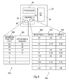
- the controller 24 comprises a processor 84, a memory 86, and an input/output interface 88.
- the memory 86 includes a centralisation file 90 and a deskew file 92.
- the centralisation file 90 includes a table 90a comprising a centroid position column 90b and a corresponding drive angle column 90c. It should be appreciated that the specific drive angle required will depend on the geometry of the transport section 10, the size of the banknote 18, and the like. The numbers provided in table 90a are merely for illustration and are not intended to be accurate. In any event, centralisation and deskew do not need to be exact, as there are variations in the sizes of the same denomination due to stretching, shrinkage, or the like.
- the deskew file 92 includes a table 92a comprising a skew angle column 92b and two corresponding drive speed columns 92c,d, one drive speed column for each of the precision stepper motors 72a,b respectively. It should be appreciated that the drive speeds shown in table 92a are provided in the form of ratios of one drive speed to the other, rather than an absolute drive speed. The numbers provided in table 92a are merely for illustration and are not intended to be accurate.
- These files 90,92 enable the processor 84 to control the media drive turret 20 and the deskew mechanism 22 so that the banknote 18 is first centralised and then deskewed, as will be described in more detail below.
- the I/O interface 88 enables the processor 84 to control the various motors 40,72a, 72b (and other motors that are not shown) that are used to transport the banknote 18 along the transport section 10 to the deposit bin 26.
- Fig 5 is a flowchart 100 illustrating steps implemented by the controller 24 in aligning the banknote 18 as it is transported through the transport section 10.
- the controller 24 transports the banknote 18 passed the media position sensors 28 and towards the media drive turret 20 (step 102).
- the media position sensors 28 comprise a linear array of sensors extending laterally across a longitudinal transport path along which the banknote 18 is conveyed.
- the controller 24 uses the media position sensors 28 to detect a leading edge 18a ( Fig 3 ) and a side edge 18b ( Fig 3 ) of the banknote 18 (step 104). The controller 24 may also detect the remaining two edges of the banknote 18.
- the processor 84 uses this edge information to calculate (i) a lateral position of a centroid of the banknote 18 relative to the guiding edge 76 ( Fig 3 ) (step 106), and (ii) a rotational (or skew) angle of the banknote 18 relative to the guiding edge 76 (step 108).
- the processor 84 then accesses the centralisation file 90 and uses the calculated lateral position of the centroid of the banknote 18 to retrieve the corresponding drive angle from table 90a (step 110). The processor 84 then activates the micro-drive motor 40 to rotate the media drive turret 20 to the retrieved drive angle (step 112).
- the processor 84 activates the stepper motor 64 to advance the drive roller 62, so that the banknote 18 is moved laterally towards an alignment position as the banknote 18 passes over the drive roller 62 (step 114).
- the processor 84 uses the rotational (or skew) angle of the banknote 18 (calculated in step 108) to retrieve from the table 92a the differential drive speeds needed to deskew the banknote 18.
- the processor 84 then applies these differential drive speed ratios to the pair of precision stepper motors 72a,b so that the banknote 18 is deskewed when it passes through the deskew mechanism 22 (step 118).
- the processor 84 then drives the centralised and deskewed banknote 18 into the deposit bin 26.
- the media alignment process 100 can then be repeated for the next media item received.
- Fig 6 is a simplified plan view illustrating the (unskewed) banknote 18 in three different positions as it passes through the transport section 10.
- the three positions are: (i) before passing through the media drive turret 20, (ii) within the media drive turret 20, and (iii) over the deskew mechanism 22.
- centroid 150 (shown as a cross) of the banknote 18 is illustrated, in addition to a centreline 152 to which the banknote 18 is to be aligned.
- the centreline 152 is spaced approximately 95mm from the guiding edge 76.
- the banknote 18 is a five Euro banknote having dimensions 120 mm by 60mm. As can be seen from Fig 6 , the banknote 18 is not skewed; that is, the side edge 18b is parallel to (and in this example abuts) the guiding edge 76. This is not unusual because transporting media items, such as banknotes, is more reliable if the media items are registered with a guiding edge.
- the banknote 18 is driven by the transport section 10 in the direction of arrows 154. This does not appreciably change either the lateral position or the rotation of the banknote 18.
- the media position sensors 28 sense the position of this banknote 18 and the processor 84 retrieves the correct drive angle from table 90a; which in this example is thirty degrees.
- the processor 84 then rotates the media drive turret 20 (only the lower turntable 36 and drive roller 62 are shown in Fig 6 ) to an angle of thirty degrees with respect to the centreline 152.
- the drive roller 62 has a diameter of 20mm and is oriented at thirty degrees to the centreline 152 because of the media drive turret 20 orientation.
- the banknote 18 When the banknote 18 reaches the media drive turret 20, the banknote 18 is then driven only by the drive roller 62 (which is angled at 30 degrees). As a result, the centroid 150 of the banknote 18 moves approximately 35mm away from the guiding edge 76, so that the centroid 150 is now aligned with the centreline 152. This movement of the banknote 18 is illustrated by arrows 156.
- the individually-controlled drive motors 70 (only drive rollers 74 are shown in Fig 6 ) are both actuated at the same speed because there is no skew (or rotation) that needs to be removed.
- the banknote 18 is then transported into the deposit bin 26 for storage.
- Fig 7 is a simplified plan view illustrating the banknote 18 in four different positions as it passes through the transport section 10. The four positions are: (i) before passing through the media drive turret 20, (ii) within the media drive turret 20, (iii) over the deskew mechanism 22, and (iv) beyond the deskew mechanism 22.
- the five Euro banknote 18 is skewed; that is, the side edge 18b is not parallel to the guiding edge 76.
- the specific example shown is a skew of minus twenty-five degrees to the guiding edge 76.
- the banknote 18 is driven by the transport drive (not shown) in the direction of arrows 164. This drive does not change either the lateral position or the rotation of the banknote 18 (which remains skewed at approximately minus twenty-five degrees).
- the media position sensors 28 sense the position of this banknote 18 (both the lateral position of the centroid 150 and the rotation).
- the centroid position 150 is approximately 67mm.
- the processor 84 then retrieves the correct drive angle from table 90a based on the sensed lateral position of the centroid 150 of the banknote 18.
- the centroid position is part-way between two entries in the table 90a, so the processor 84 applies a linear interpolation.
- the drive angle is interpolated as approximately twenty-three degrees.
- the processor 84 also retrieves the correct drive speed ratios from table 92a based on the sensed rotation of the banknote 18; that is, minus twenty-five degrees.
- the drive speed ratios from table 92a for drive roller 74a and drive roller 74b, respectively, are 3:1 (0.75 and 0.25).
- the processor 84 then rotates the media drive turret 20 (only the lower turntable 36 and drive roller 62 are shown in Fig 7 ) to the retrieved correct drive angle (which in this example is approximately twenty-three degrees with respect to the centreline 152).
- the drive roller 62 is therefore oriented at twenty-three degrees to the centreline 152.
- the banknote 18 When the banknote 18 reaches the media drive turret 20, the banknote 18 is then driven only by the drive roller 62 (which is angled at 23 degrees). As a result, the centroid 150 of the banknote 18 moves approximately 28mm away from the guiding edge 76, so that the centroid 150 is now aligned with the centreline 152. This movement of the banknote 18 is illustrated by arrows 166.
- the processor 84 uses the drive ratios retrieved from table 92a to drive the individually-controlled drive motors 70a,b (only drive rollers 74a,b are shown in Fig 7 ) at different speeds.
- arrow 168a which is larger than arrow 168b
- the side 18b of the banknote 18 that is nearest the guide edge 76 is driven faster than the opposite side 18c of the banknote 18. This removes the rotation from the banknote 18 (in other words, this deskews the banknote 18).
- the banknote 18 is then transported by the processor 84 towards and into the deposit bin 26 in a centralised and deskewed orientation.
- the drive member in the media drive turret may comprise only an upper roller or only a lower roller.
- the lower roller may comprise a driven roller
- the upper roller may comprise an idler roller.
- the idler roller and the driven roller may have complementary, interengaging formations.
- skew sensors may be provided in addition to, and spaced apart from, the media position sensors 28.
- skew sensors may be located upstream of both the deskew mechanism 22 and the media drive turret 20, or only upstream of the media position sensors 28.
- the media item 18 may comprise a cheque, a ticket, or the like.
- a finer control of the media drive turret angle may be desired.
- smaller pulleys may be provided on the motor double-ended shaft 42 than the pulleys 50,52 on the media drive turret 20.
- Finer position increments can also be achieved by using a micro-stepping version of the motor 40 and controlling the motor position to fractions of a step angle.
- the steps of the methods described herein may be carried out in any suitable order, or simultaneously where appropriate.
- the methods described herein may be performed by software in machine readable form on a tangible storage medium or as a propagating signal.
Landscapes
- Physics & Mathematics (AREA)
- General Physics & Mathematics (AREA)
- Engineering & Computer Science (AREA)
- Automation & Control Theory (AREA)
- Registering Or Overturning Sheets (AREA)
- Specific Conveyance Elements (AREA)
Applications Claiming Priority (1)
| Application Number | Priority Date | Filing Date | Title |
|---|---|---|---|
| US13/772,057 US9098089B2 (en) | 2013-02-20 | 2013-02-20 | Media alignment |
Publications (3)
| Publication Number | Publication Date |
|---|---|
| EP2769948A2 true EP2769948A2 (de) | 2014-08-27 |
| EP2769948A3 EP2769948A3 (de) | 2018-02-07 |
| EP2769948B1 EP2769948B1 (de) | 2023-04-26 |
Family
ID=50156545
Family Applications (1)
| Application Number | Title | Priority Date | Filing Date |
|---|---|---|---|
| EP14152208.6A Active EP2769948B1 (de) | 2013-02-20 | 2014-01-22 | Medienausrichtung |
Country Status (3)
| Country | Link |
|---|---|
| US (1) | US9098089B2 (de) |
| EP (1) | EP2769948B1 (de) |
| CN (1) | CN103991746B (de) |
Cited By (1)
| Publication number | Priority date | Publication date | Assignee | Title |
|---|---|---|---|---|
| WO2019203890A1 (en) | 2018-04-20 | 2019-10-24 | Crane Payment Innovations, Inc. | Active steering system |
Families Citing this family (3)
| Publication number | Priority date | Publication date | Assignee | Title |
|---|---|---|---|---|
| DE102017105845A1 (de) * | 2017-03-17 | 2018-09-20 | Wincor Nixdorf International Gmbh | Vorrichtung zum Ausrichten von Wertscheinen |
| US12505468B2 (en) * | 2018-12-14 | 2025-12-23 | Productive Application Solutions, Inc. | Turret system and method for portable projection deployment |
| US11276267B2 (en) * | 2019-08-30 | 2022-03-15 | Ncr Corporation | Media rotation mechanism |
Family Cites Families (11)
| Publication number | Priority date | Publication date | Assignee | Title |
|---|---|---|---|---|
| US5169140A (en) * | 1991-11-25 | 1992-12-08 | Xerox Corporation | Method and apparatus for deskewing and side registering a sheet |
| DE59300234D1 (de) * | 1992-09-08 | 1995-07-06 | Bay Otto | Verfahren und Vorrichtung zur lagerichtigen Zufuhr von Blattbogen zu einer Faltmaschine. |
| US5697609A (en) * | 1996-06-26 | 1997-12-16 | Xerox Corporation | Lateral sheet pre-registration device |
| JP4601792B2 (ja) * | 2000-09-14 | 2010-12-22 | 株式会社東芝 | 紙葉類処理装置 |
| US6736394B2 (en) * | 2002-09-06 | 2004-05-18 | Xerox Corporation | Printer lateral and deskew sheet registration system |
| US7027076B2 (en) * | 2003-07-28 | 2006-04-11 | Hewlett-Packard Development Company, L.P. | Media-position media sensor |
| DE102004060191A1 (de) * | 2004-12-14 | 2006-06-29 | Wincor Nixdorf International Gmbh | Vorrichtung zum Ausrichten von Wertscheinen |
| JP2010285244A (ja) * | 2009-06-10 | 2010-12-24 | Toshiba Corp | 姿勢変換装置、および紙葉類処理装置 |
| US20110042887A1 (en) * | 2009-08-18 | 2011-02-24 | Kallin Fredrik L N | Document deskewing module and methods of operating a document deskewing module for a self-service bunch document depositing terminal |
| JP5717418B2 (ja) * | 2010-11-30 | 2015-05-13 | キヤノン株式会社 | シート搬送装置、これを用いた画像読取装置、及び画像形成装置 |
| KR101258773B1 (ko) * | 2011-08-02 | 2013-04-29 | 노틸러스효성 주식회사 | 매체 정렬 장치 |
-
2013
- 2013-02-20 US US13/772,057 patent/US9098089B2/en active Active
-
2014
- 2014-01-22 EP EP14152208.6A patent/EP2769948B1/de active Active
- 2014-02-14 CN CN201410051634.XA patent/CN103991746B/zh active Active
Non-Patent Citations (1)
| Title |
|---|
| None |
Cited By (2)
| Publication number | Priority date | Publication date | Assignee | Title |
|---|---|---|---|---|
| WO2019203890A1 (en) | 2018-04-20 | 2019-10-24 | Crane Payment Innovations, Inc. | Active steering system |
| EP3781503A4 (de) * | 2018-04-20 | 2022-02-23 | Crane Payment Innovations, Inc. | Aktives lenksystem |
Also Published As
| Publication number | Publication date |
|---|---|
| EP2769948A3 (de) | 2018-02-07 |
| US9098089B2 (en) | 2015-08-04 |
| EP2769948B1 (de) | 2023-04-26 |
| US20140236344A1 (en) | 2014-08-21 |
| CN103991746A (zh) | 2014-08-20 |
| CN103991746B (zh) | 2017-05-31 |
Similar Documents
| Publication | Publication Date | Title |
|---|---|---|
| CN107265150B (zh) | 纸币运送装置 | |
| EP2769948B1 (de) | Medienausrichtung | |
| KR100991734B1 (ko) | 매체표리 반전장치 | |
| KR20170113591A (ko) | 적재 및 분배 모듈 | |
| EP1731456B1 (de) | Schräglaufkorrektur für papier- und banknotenaufnahme-/abgabevorrichtung | |
| US10504315B2 (en) | Clamping of media items | |
| EP2832673A2 (de) | Vorrichtung zum Fördern eines Mediengegenstands, Medeiengegenstandbearbeitungsmodul, und Verfahren zum Fördern eines Mediengegenstands | |
| EP2843631B1 (de) | Bogenunterscheidungsvorrichtung und Bogenverarbeitungsvorrichtung | |
| WO2010089766A1 (en) | Skew correction using split-roller | |
| JP6863847B2 (ja) | 紙葉類取扱装置、自動取引装置、および紙葉類仕分け装置 | |
| KR101455238B1 (ko) | 지폐정렬장치 | |
| CN105492355A (zh) | 纸页类蓄积装置和纸页类处理装置 | |
| EP0769466B1 (de) | Stapeltransportvorrichtung | |
| JP2003312895A (ja) | 重走検知装置 | |
| US9472041B2 (en) | Clamping of media items | |
| US10640317B2 (en) | Anti-skew straightening mechanism | |
| KR20140133220A (ko) | 지폐정렬장치 | |
| JP2023031462A (ja) | 紙幣整列機構及びこれを用いた紙幣識別装置 | |
| KR20160149778A (ko) | 매체 이송 장치 | |
| KR20150000136A (ko) | 지폐정렬장치 | |
| WO2018163649A1 (ja) | 紙葉類処理装置 | |
| WO2019016964A1 (ja) | 紙葉類搬送装置、紙葉類取扱装置及び紙葉類搬送方法 | |
| CN104937643A (zh) | 纸页类收纳装置、纸页类处理装置以及纸页类输送装置 | |
| JP2015009949A (ja) | 紙葉類搬送装置および紙葉類搬送方法 | |
| KR20140142922A (ko) | 지폐정렬장치 |
Legal Events
| Date | Code | Title | Description |
|---|---|---|---|
| PUAI | Public reference made under article 153(3) epc to a published international application that has entered the european phase |
Free format text: ORIGINAL CODE: 0009012 |
|
| 17P | Request for examination filed |
Effective date: 20140122 |
|
| AK | Designated contracting states |
Kind code of ref document: A2 Designated state(s): AL AT BE BG CH CY CZ DE DK EE ES FI FR GB GR HR HU IE IS IT LI LT LU LV MC MK MT NL NO PL PT RO RS SE SI SK SM TR |
|
| AX | Request for extension of the european patent |
Extension state: BA ME |
|
| PUAL | Search report despatched |
Free format text: ORIGINAL CODE: 0009013 |
|
| AK | Designated contracting states |
Kind code of ref document: A3 Designated state(s): AL AT BE BG CH CY CZ DE DK EE ES FI FR GB GR HR HU IE IS IT LI LT LU LV MC MK MT NL NO PL PT RO RS SE SI SK SM TR |
|
| AX | Request for extension of the european patent |
Extension state: BA ME |
|
| RIC1 | Information provided on ipc code assigned before grant |
Ipc: B65H 7/10 20060101ALI20180102BHEP Ipc: B65H 9/00 20060101ALI20180102BHEP Ipc: B65H 9/16 20060101AFI20180102BHEP |
|
| RAP1 | Party data changed (applicant data changed or rights of an application transferred) |
Owner name: NCR CORPORATION |
|
| STAA | Information on the status of an ep patent application or granted ep patent |
Free format text: STATUS: REQUEST FOR EXAMINATION WAS MADE |
|
| R17P | Request for examination filed (corrected) |
Effective date: 20180807 |
|
| RBV | Designated contracting states (corrected) |
Designated state(s): AL AT BE BG CH CY CZ DE DK EE ES FI FR GB GR HR HU IE IS IT LI LT LU LV MC MK MT NL NO PL PT RO RS SE SI SK SM TR |
|
| STAA | Information on the status of an ep patent application or granted ep patent |
Free format text: STATUS: EXAMINATION IS IN PROGRESS |
|
| 17Q | First examination report despatched |
Effective date: 20210118 |
|
| GRAP | Despatch of communication of intention to grant a patent |
Free format text: ORIGINAL CODE: EPIDOSNIGR1 |
|
| STAA | Information on the status of an ep patent application or granted ep patent |
Free format text: STATUS: GRANT OF PATENT IS INTENDED |
|
| INTG | Intention to grant announced |
Effective date: 20230109 |
|
| GRAS | Grant fee paid |
Free format text: ORIGINAL CODE: EPIDOSNIGR3 |
|
| GRAA | (expected) grant |
Free format text: ORIGINAL CODE: 0009210 |
|
| STAA | Information on the status of an ep patent application or granted ep patent |
Free format text: STATUS: THE PATENT HAS BEEN GRANTED |
|
| AK | Designated contracting states |
Kind code of ref document: B1 Designated state(s): AL AT BE BG CH CY CZ DE DK EE ES FI FR GB GR HR HU IE IS IT LI LT LU LV MC MK MT NL NO PL PT RO RS SE SI SK SM TR |
|
| REG | Reference to a national code |
Ref country code: GB Ref legal event code: FG4D |
|
| REG | Reference to a national code |
Ref country code: CH Ref legal event code: EP |
|
| REG | Reference to a national code |
Ref country code: DE Ref legal event code: R096 Ref document number: 602014086761 Country of ref document: DE |
|
| REG | Reference to a national code |
Ref country code: DE Ref legal event code: R084 Ref document number: 602014086761 Country of ref document: DE |
|
| REG | Reference to a national code |
Ref country code: AT Ref legal event code: REF Ref document number: 1562697 Country of ref document: AT Kind code of ref document: T Effective date: 20230515 |
|
| REG | Reference to a national code |
Ref country code: IE Ref legal event code: FG4D |
|
| REG | Reference to a national code |
Ref country code: GB Ref legal event code: 746 Effective date: 20230510 |
|
| P01 | Opt-out of the competence of the unified patent court (upc) registered |
Effective date: 20230506 |
|
| REG | Reference to a national code |
Ref country code: LT Ref legal event code: MG9D |
|
| REG | Reference to a national code |
Ref country code: NL Ref legal event code: MP Effective date: 20230426 |
|
| REG | Reference to a national code |
Ref country code: AT Ref legal event code: MK05 Ref document number: 1562697 Country of ref document: AT Kind code of ref document: T Effective date: 20230426 |
|
| PG25 | Lapsed in a contracting state [announced via postgrant information from national office to epo] |
Ref country code: NL Free format text: LAPSE BECAUSE OF FAILURE TO SUBMIT A TRANSLATION OF THE DESCRIPTION OR TO PAY THE FEE WITHIN THE PRESCRIBED TIME-LIMIT Effective date: 20230426 |
|
| PG25 | Lapsed in a contracting state [announced via postgrant information from national office to epo] |
Ref country code: SE Free format text: LAPSE BECAUSE OF FAILURE TO SUBMIT A TRANSLATION OF THE DESCRIPTION OR TO PAY THE FEE WITHIN THE PRESCRIBED TIME-LIMIT Effective date: 20230426 Ref country code: PT Free format text: LAPSE BECAUSE OF FAILURE TO SUBMIT A TRANSLATION OF THE DESCRIPTION OR TO PAY THE FEE WITHIN THE PRESCRIBED TIME-LIMIT Effective date: 20230828 Ref country code: NO Free format text: LAPSE BECAUSE OF FAILURE TO SUBMIT A TRANSLATION OF THE DESCRIPTION OR TO PAY THE FEE WITHIN THE PRESCRIBED TIME-LIMIT Effective date: 20230726 Ref country code: ES Free format text: LAPSE BECAUSE OF FAILURE TO SUBMIT A TRANSLATION OF THE DESCRIPTION OR TO PAY THE FEE WITHIN THE PRESCRIBED TIME-LIMIT Effective date: 20230426 Ref country code: AT Free format text: LAPSE BECAUSE OF FAILURE TO SUBMIT A TRANSLATION OF THE DESCRIPTION OR TO PAY THE FEE WITHIN THE PRESCRIBED TIME-LIMIT Effective date: 20230426 |
|
| PG25 | Lapsed in a contracting state [announced via postgrant information from national office to epo] |
Ref country code: RS Free format text: LAPSE BECAUSE OF FAILURE TO SUBMIT A TRANSLATION OF THE DESCRIPTION OR TO PAY THE FEE WITHIN THE PRESCRIBED TIME-LIMIT Effective date: 20230426 Ref country code: PL Free format text: LAPSE BECAUSE OF FAILURE TO SUBMIT A TRANSLATION OF THE DESCRIPTION OR TO PAY THE FEE WITHIN THE PRESCRIBED TIME-LIMIT Effective date: 20230426 Ref country code: LV Free format text: LAPSE BECAUSE OF FAILURE TO SUBMIT A TRANSLATION OF THE DESCRIPTION OR TO PAY THE FEE WITHIN THE PRESCRIBED TIME-LIMIT Effective date: 20230426 Ref country code: LT Free format text: LAPSE BECAUSE OF FAILURE TO SUBMIT A TRANSLATION OF THE DESCRIPTION OR TO PAY THE FEE WITHIN THE PRESCRIBED TIME-LIMIT Effective date: 20230426 Ref country code: IS Free format text: LAPSE BECAUSE OF FAILURE TO SUBMIT A TRANSLATION OF THE DESCRIPTION OR TO PAY THE FEE WITHIN THE PRESCRIBED TIME-LIMIT Effective date: 20230826 Ref country code: HR Free format text: LAPSE BECAUSE OF FAILURE TO SUBMIT A TRANSLATION OF THE DESCRIPTION OR TO PAY THE FEE WITHIN THE PRESCRIBED TIME-LIMIT Effective date: 20230426 Ref country code: GR Free format text: LAPSE BECAUSE OF FAILURE TO SUBMIT A TRANSLATION OF THE DESCRIPTION OR TO PAY THE FEE WITHIN THE PRESCRIBED TIME-LIMIT Effective date: 20230727 |
|
| PG25 | Lapsed in a contracting state [announced via postgrant information from national office to epo] |
Ref country code: FI Free format text: LAPSE BECAUSE OF FAILURE TO SUBMIT A TRANSLATION OF THE DESCRIPTION OR TO PAY THE FEE WITHIN THE PRESCRIBED TIME-LIMIT Effective date: 20230426 |
|
| PG25 | Lapsed in a contracting state [announced via postgrant information from national office to epo] |
Ref country code: SK Free format text: LAPSE BECAUSE OF FAILURE TO SUBMIT A TRANSLATION OF THE DESCRIPTION OR TO PAY THE FEE WITHIN THE PRESCRIBED TIME-LIMIT Effective date: 20230426 |
|
| REG | Reference to a national code |
Ref country code: DE Ref legal event code: R097 Ref document number: 602014086761 Country of ref document: DE |
|
| PG25 | Lapsed in a contracting state [announced via postgrant information from national office to epo] |
Ref country code: SM Free format text: LAPSE BECAUSE OF FAILURE TO SUBMIT A TRANSLATION OF THE DESCRIPTION OR TO PAY THE FEE WITHIN THE PRESCRIBED TIME-LIMIT Effective date: 20230426 Ref country code: SK Free format text: LAPSE BECAUSE OF FAILURE TO SUBMIT A TRANSLATION OF THE DESCRIPTION OR TO PAY THE FEE WITHIN THE PRESCRIBED TIME-LIMIT Effective date: 20230426 Ref country code: RO Free format text: LAPSE BECAUSE OF FAILURE TO SUBMIT A TRANSLATION OF THE DESCRIPTION OR TO PAY THE FEE WITHIN THE PRESCRIBED TIME-LIMIT Effective date: 20230426 Ref country code: EE Free format text: LAPSE BECAUSE OF FAILURE TO SUBMIT A TRANSLATION OF THE DESCRIPTION OR TO PAY THE FEE WITHIN THE PRESCRIBED TIME-LIMIT Effective date: 20230426 Ref country code: DK Free format text: LAPSE BECAUSE OF FAILURE TO SUBMIT A TRANSLATION OF THE DESCRIPTION OR TO PAY THE FEE WITHIN THE PRESCRIBED TIME-LIMIT Effective date: 20230426 Ref country code: CZ Free format text: LAPSE BECAUSE OF FAILURE TO SUBMIT A TRANSLATION OF THE DESCRIPTION OR TO PAY THE FEE WITHIN THE PRESCRIBED TIME-LIMIT Effective date: 20230426 |
|
| PLBE | No opposition filed within time limit |
Free format text: ORIGINAL CODE: 0009261 |
|
| STAA | Information on the status of an ep patent application or granted ep patent |
Free format text: STATUS: NO OPPOSITION FILED WITHIN TIME LIMIT |
|
| 26N | No opposition filed |
Effective date: 20240129 |
|
| PG25 | Lapsed in a contracting state [announced via postgrant information from national office to epo] |
Ref country code: SI Free format text: LAPSE BECAUSE OF FAILURE TO SUBMIT A TRANSLATION OF THE DESCRIPTION OR TO PAY THE FEE WITHIN THE PRESCRIBED TIME-LIMIT Effective date: 20230426 |
|
| PG25 | Lapsed in a contracting state [announced via postgrant information from national office to epo] |
Ref country code: SI Free format text: LAPSE BECAUSE OF FAILURE TO SUBMIT A TRANSLATION OF THE DESCRIPTION OR TO PAY THE FEE WITHIN THE PRESCRIBED TIME-LIMIT Effective date: 20230426 Ref country code: IT Free format text: LAPSE BECAUSE OF FAILURE TO SUBMIT A TRANSLATION OF THE DESCRIPTION OR TO PAY THE FEE WITHIN THE PRESCRIBED TIME-LIMIT Effective date: 20230426 |
|
| PG25 | Lapsed in a contracting state [announced via postgrant information from national office to epo] |
Ref country code: MC Free format text: LAPSE BECAUSE OF FAILURE TO SUBMIT A TRANSLATION OF THE DESCRIPTION OR TO PAY THE FEE WITHIN THE PRESCRIBED TIME-LIMIT Effective date: 20230426 |
|
| PG25 | Lapsed in a contracting state [announced via postgrant information from national office to epo] |
Ref country code: MC Free format text: LAPSE BECAUSE OF FAILURE TO SUBMIT A TRANSLATION OF THE DESCRIPTION OR TO PAY THE FEE WITHIN THE PRESCRIBED TIME-LIMIT Effective date: 20230426 |
|
| REG | Reference to a national code |
Ref country code: CH Ref legal event code: PL |
|
| PG25 | Lapsed in a contracting state [announced via postgrant information from national office to epo] |
Ref country code: LU Free format text: LAPSE BECAUSE OF NON-PAYMENT OF DUE FEES Effective date: 20240122 |
|
| REG | Reference to a national code |
Ref country code: DE Ref legal event code: R081 Ref document number: 602014086761 Country of ref document: DE Owner name: CARDTRONICS USA, INC. (GESELLSCHAFT NACH DEN G, US Free format text: FORMER OWNER: NCR CORPORATION, ATLANTA, GA, US |
|
| PG25 | Lapsed in a contracting state [announced via postgrant information from national office to epo] |
Ref country code: LU Free format text: LAPSE BECAUSE OF NON-PAYMENT OF DUE FEES Effective date: 20240122 |
|
| PG25 | Lapsed in a contracting state [announced via postgrant information from national office to epo] |
Ref country code: BE Free format text: LAPSE BECAUSE OF NON-PAYMENT OF DUE FEES Effective date: 20240131 |
|
| PG25 | Lapsed in a contracting state [announced via postgrant information from national office to epo] |
Ref country code: CH Free format text: LAPSE BECAUSE OF NON-PAYMENT OF DUE FEES Effective date: 20240131 |
|
| PG25 | Lapsed in a contracting state [announced via postgrant information from national office to epo] |
Ref country code: CH Free format text: LAPSE BECAUSE OF NON-PAYMENT OF DUE FEES Effective date: 20240131 Ref country code: BE Free format text: LAPSE BECAUSE OF NON-PAYMENT OF DUE FEES Effective date: 20240131 |
|
| REG | Reference to a national code |
Ref country code: BE Ref legal event code: MM Effective date: 20240131 |
|
| PG25 | Lapsed in a contracting state [announced via postgrant information from national office to epo] |
Ref country code: BG Free format text: LAPSE BECAUSE OF FAILURE TO SUBMIT A TRANSLATION OF THE DESCRIPTION OR TO PAY THE FEE WITHIN THE PRESCRIBED TIME-LIMIT Effective date: 20230426 |
|
| PG25 | Lapsed in a contracting state [announced via postgrant information from national office to epo] |
Ref country code: BG Free format text: LAPSE BECAUSE OF FAILURE TO SUBMIT A TRANSLATION OF THE DESCRIPTION OR TO PAY THE FEE WITHIN THE PRESCRIBED TIME-LIMIT Effective date: 20230426 |
|
| PG25 | Lapsed in a contracting state [announced via postgrant information from national office to epo] |
Ref country code: IE Free format text: LAPSE BECAUSE OF NON-PAYMENT OF DUE FEES Effective date: 20240122 |
|
| PG25 | Lapsed in a contracting state [announced via postgrant information from national office to epo] |
Ref country code: IE Free format text: LAPSE BECAUSE OF NON-PAYMENT OF DUE FEES Effective date: 20240122 |
|
| PG25 | Lapsed in a contracting state [announced via postgrant information from national office to epo] |
Ref country code: CY Free format text: LAPSE BECAUSE OF FAILURE TO SUBMIT A TRANSLATION OF THE DESCRIPTION OR TO PAY THE FEE WITHIN THE PRESCRIBED TIME-LIMIT; INVALID AB INITIO Effective date: 20140122 |
|
| PG25 | Lapsed in a contracting state [announced via postgrant information from national office to epo] |
Ref country code: HU Free format text: LAPSE BECAUSE OF FAILURE TO SUBMIT A TRANSLATION OF THE DESCRIPTION OR TO PAY THE FEE WITHIN THE PRESCRIBED TIME-LIMIT; INVALID AB INITIO Effective date: 20140122 |
|
| PG25 | Lapsed in a contracting state [announced via postgrant information from national office to epo] |
Ref country code: TR Free format text: LAPSE BECAUSE OF FAILURE TO SUBMIT A TRANSLATION OF THE DESCRIPTION OR TO PAY THE FEE WITHIN THE PRESCRIBED TIME-LIMIT Effective date: 20230426 |
|
| PGFP | Annual fee paid to national office [announced via postgrant information from national office to epo] |
Ref country code: GB Payment date: 20260127 Year of fee payment: 13 |
|
| PGFP | Annual fee paid to national office [announced via postgrant information from national office to epo] |
Ref country code: DE Payment date: 20260128 Year of fee payment: 13 |
|
| PGFP | Annual fee paid to national office [announced via postgrant information from national office to epo] |
Ref country code: FR Payment date: 20260126 Year of fee payment: 13 |