EP2770125A2 - Douche-WC et dispositif de raccordement associé - Google Patents
Douche-WC et dispositif de raccordement associé Download PDFInfo
- Publication number
- EP2770125A2 EP2770125A2 EP14169328.3A EP14169328A EP2770125A2 EP 2770125 A2 EP2770125 A2 EP 2770125A2 EP 14169328 A EP14169328 A EP 14169328A EP 2770125 A2 EP2770125 A2 EP 2770125A2
- Authority
- EP
- European Patent Office
- Prior art keywords
- shower
- toilet
- connection
- connection device
- line
- Prior art date
- Legal status (The legal status is an assumption and is not a legal conclusion. Google has not performed a legal analysis and makes no representation as to the accuracy of the status listed.)
- Withdrawn
Links
Images

Classifications
-
- E—FIXED CONSTRUCTIONS
- E03—WATER SUPPLY; SEWERAGE
- E03D—WATER-CLOSETS OR URINALS WITH FLUSHING DEVICES; FLUSHING VALVES THEREFOR
- E03D11/00—Other component parts of water-closets, e.g. noise-reducing means in the flushing system, flushing pipes mounted in the bowl, seals for the bowl outlet, devices preventing overflow of the bowl contents; devices forming a water seal in the bowl after flushing, devices eliminating obstructions in the bowl outlet or preventing backflow of water and excrements from the waterpipe
- E03D11/13—Parts or details of bowls; Special adaptations of pipe joints or couplings for use with bowls, e.g. provisions in bowl construction preventing backflow of waste-water from the bowl in the flushing pipe or cistern, provisions for a secondary flushing, for noise-reducing
- E03D11/14—Means for connecting the bowl to the wall, e.g. to a wall outlet
- E03D11/143—Mounting frames for toilets and urinals
-
- E—FIXED CONSTRUCTIONS
- E03—WATER SUPPLY; SEWERAGE
- E03D—WATER-CLOSETS OR URINALS WITH FLUSHING DEVICES; FLUSHING VALVES THEREFOR
- E03D9/00—Sanitary or other accessories for lavatories ; Devices for cleaning or disinfecting the toilet room or the toilet bowl; Devices for eliminating smells
- E03D9/08—Devices in the bowl producing upwardly-directed sprays; Modifications of the bowl for use with such devices ; Bidets; Combinations of bowls with urinals or bidets; Hot-air or other devices mounted in or on the bowl, urinal or bidet for cleaning or disinfecting
Definitions
- the invention relates to a mounting frame for a shower toilet, a matching shower toilet and a toilet arrangement with this mounting frame and the shower toilet.
- a toilet is additionally equipped with at least one shower for cleaning the abdomen of a user, which is often referred to as a short shower.
- a motorized-moving shower arm of the sub-shower can advance to an operating operation in the toilet bowl and direct a shower water jet upward and go back to function.
- shower facilities are equipped with other facilities, such as water heaters such as boilers or water heaters, hair dryer facilities, shower arm cleaners etc.
- water heaters such as boilers or water heaters, hair dryer facilities, shower arm cleaners etc.
- shower facilities are usually an additional shower water connection, for example as cold water connection of a water heater in the shower toilet, and an electric Connection, for example, to supply a water heater, a drive motor or other facilities provided.
- technical parts of the shower device can also be arranged "behind" the actual toilet body in a mounting wall;
- a water heater could be provided there, so that the mentioned additional shower water connection can also affect already heated water.
- WCs are connected to a wall behind, in particular if, as preferred here, they have no base and hang freely.
- a toilet connection device is provided as or in a mounting frame for the toilet.
- Such mounting frame regularly consist of two right and left outside arranged vertical struts of a support frame and held therebetween transverse structures, such as horizontal struts or mounting plates.
- load-carrying connection devices for suspending the WC body, connecting pieces for the rinsing water and the waste water of the toilet bowl and connection devices for the mentioned specific lines of the shower device are formed on these mounting frames.
- the object of the invention is to develop a shower toilet in terms of convenient connection options and to create a corresponding toilet connection device.
- the invention relates to a toilet connection device according to claim 1, a shower toilet according to claim 8 and a corresponding use of the connection device and the shower toilet.
- At least one further connection device for a specific line of the shower device is centered with respect to the width in the prior art, d. H. specifically within the middle 300 mm, but outside the middle 30 mm.
- the center should be defined by the middle of the wall-side and toilet-side connection device of Spülwasserzu effet and the sewer line.
- the shower line connection device can be an electrical or even a shower water connection.
- further internal connection positions are increasingly preferred, at least up to a certain upper limit.
- the following central widths are increasingly preferred as upper limits (in each case in mm): 275, 250, 225, 200, 175, 150, 125, 120, 115, 110. More preferred lower limits are in the following order: 40 mm , 50 mm, 60 mm, 70 mm, 80 mm.
- terminal positions for the shower line connection device according to the invention are basically "centered" than in the prior art, but even more preferably even more centrally than the outer and most preferably even more centrally than the inner usual position of the mechanical attachment.
- This central arrangement facilitates the accessibility of the connection devices for a fitter or service technician, in particular from below and allows or uses a corresponding embodiment of the back of the toilet .
- WCs have around the central Spülwasserzu effeten and sewers of the toilet bowl around one of the Rear left area on; in other words, the contact surfaces of the toilet body are on the mounting wall outside of this free area.
- a corresponding arrangement of the mentioned connection devices thus allows a design of the WC, in which one can reach the connection devices from below, without having to disassemble the toilet body. This applies depending on the application for an achievement by hand or at least with a tool.
- connection devices are furthermore located just outside the area of the flushing water supply line for the toilet bowl and with respect to the vertical extent with respect to the horizontal extension approximately at the level of the lower edge and also at the height of the load of the toilet body supporting connection devices.
- these are only preferred and by no means compelling positions.
- the center of the at least one shower line connection device is located outside the actual middle, specifically the middle 30 mm.
- anschltass is meant in particular a separable interface, so for example, an electrical plug-in contact or a watertight coupling between two shower pipe sections.
- this term also refers to a wall-side or toilet-side device, which determines only the wall-side position of a corresponding shower line or the WG.
- the actually separable interfaces could also be slightly in front of the plane of the wall or the mounting frame; but they are preferably approximately in this plane.
- the analogous applies to a transition Duschleims Fantasy at the WC backside and an arrangement of an interface behind the wall front.
- a shower line connection position is on the one hand below the upper edge and preferably the center line of the flushing water supply connection for the toilet bowl and on the other hand above the lower edge and preferably above the center line of a waste water connection for the toilet bowl for reasons of accessibility and for simplicity of construction.
- Particularly preferred in terms of vertical positioning are arrangements in the area around the load-bearing connection devices, in particular between 15% above and 40% below, the percentage values relating to the vertical height of the load-bearing connection devices relative to the ground. Further preferred are upper limits of plus 10% and plus 5% and, independently, lower limits of minus 30%, minus 20% and minus 10%.
- a ground position in the middle of the adjustment range is meant. The statements relate again to at least one shower line.
- connection means for the specific shower lines of shower toilets were positioned very far outside, which concerns the horizontal direction. They were either in a two vertical frame struts connecting mounting plate directly within the frame struts or even outside the frame struts and thus in the sense of claim 1 at about 390 mm or above (195 mm distance to the center). This probably has the reason that in many shower toilets, the shower lines not at all behind the toilet body visible concealed but visible next to it. In particular, this applies to shower toilets with a shower attachment, ie a mounted on a common toilet body between the toilet seat and the mounting wall technology housing that contains the necessary technology for the shower equipment outside and above the rest of the toilet body.
- the invention also relates to toilet connection devices, which are designed for a position according to the invention of a shower line connection device and also for a further outward position.
- a guided in a mounting rack line or run in the mounting frame pipe channel could be designed to be sufficiently flexible, so that they can be converted, for example, between a further inside and a further outward position in the mounting frame.
- such a pipe channel is branched and thus offers two different pipe channel pieces to choose from, each of which fits to its own connection position.
- a pipe channel can be guided downwards for approximately approximately one of the frame struts by a valve arranged above a cistern integrated in a mounting frame, and then somewhat branching out above the connection positions to be approximately V-shaped.
- FIG. 1 can be seen in a toilet toilet body shown in perspective, and seen from obliquely behind and slightly elevated.
- FIG. 1 is also cut, so shows only one half of the toilet seat.
- a classic toilet bowl 1 a knee 2 a drain siphon and, subsequently, a right-facing pipe socket 3 as sewer line connection device of the toilet to the wall connection.
- a further pipe socket 4 namely a Spülwasserzu effets connection device.
- the toilet bowl body Above the flushing channel, the toilet bowl body is essentially horizontal and is closed flat upwards.
- a known shower attachment can be constructed, from which, for example, a shower arm can be moved into the upper opening of the toilet bowl 1 obliquely downwards and forwards.
- a shower arm can be moved into the upper opening of the toilet bowl 1 obliquely downwards and forwards.
- shower heads are even with regard to their power and shower water connection lines with lateral connection devices or laterally outgoing connection lines provided.
- the side here is the area approximately above the in FIG. 1 upper rear edge of the lavatory body in the straight area, to the right of the opening of the bowl.
- FIG. 1 shows FIG. 1 on the right an approximately triangular profile rear wall portion 6 for engagement with a mounting wall.
- This profile rear wall portion 6 is closed between the illustrated approximately vertical (V-shaped) frame struts and the horizontal struts. It contains a recognizable cylindrical hole 7 as Monfiageloch for a bolt for mechanical attachment of Klosett stressess, so as a load-bearing connection device.
- This mechanical assembly is conventional and common.
- FIG. 2 shows largely the same toilet body, with the same reference numerals are used accordingly. Here is the line of sight exactly from the back horizontally on the back, with the second half of the toilet bowl body is shown.
- the corresponding lines 8 or 9 can continue from there, for example, obliquely upwards and outwards and run up inside inner cavities of the ceramic toilet body behind the profile rear wall 6 and, for example, by an in FIG. 1 not provided through opening in the top of the toilet seat can be passed through in a shower attachment.
- the cables can be used in FIG. 2 shown position due to their own dimensional stability and / or hold as a result of a fixation, for example, the ceramic toilet body.
- they can be glued by an adhesive body.
- flexible lines with an undefined position are conceivable, which are brought into the illustrated positions during assembly and are designed to that extent.
- a fitter or service technician can reach the positions according to the invention of the shower lines 8 and 9 without any particular difficulties by hand or with a tool from below, even in the assembled state of the shower toilet. For this purpose, he can pass by the sewer pipe socket 3 and does not have to grab in the slightly more difficult area between this and the pipe socket 4 of Spülwasserzutechnisch "around the corner". It can also be seen that the positions of the lines 8 and 9 are variable depending on the detailed design of the rear contact surface of the toilet seat body to different sides or can be. In particular, the area within the profile rear walls 6 could also be partially accessible and thus could also be positions horizontally outside the mounting holes 7 for the load-bearing bolts into consideration.
- the illustrated pipe sections 8 and 9 are essentially symbolic. Preferably, they terminate in an interface, for example, with a connector or other connector means located in or slightly in front of or behind the illustrated area. As already explained, however, the "interfaces" could also lie within the toilet bowl body or in the installation wall, and nevertheless the drawn or comparable positions of the lines can be selected.
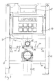
- FIG. 3 shows a corresponding toilet connection device.
- This has, in a conventional manner, a mounting frame with two vertical steel profile struts 10 on adjustable feet and a lower steel profile cross-member 11 and another upper (not exactly drawn) steel profile cross-beam.
- the cross-beam 11 carries an angle pipe section 12, namely the wall-side connection device for the sewer line of the toilet.
- a cross plate 13 as a mounting plate with optional inner and outer mounting holes 14 and 15 for the aforementioned fastening bolts, so matching the Frelöcherri 7 in Figures 1 and 2 , intended.
- the inner mounting holes 15 are in the in FIG. 1 and FIG.
- the mounting plate 13 centrally contains a recess with a semicircular shape above and rectangular shape below, through which a wall-side connection device 16 for the Spülwasserzu effet, so complementary to the pipe socket 4 in the Figures 1 and 2 protrudes. Above the mounting plate 13 with these devices is a cistern 17, so a water tank for the Spülwasserzu effet and above this a trigger mechanism 18 for the flushing process.
- FIG. 3 Conventional and would be used in conjunction with a toilet seat according to FIG. 1 form a conventional toilet arrangement.
- Supplemented lines 8 and 9 are in FIG. 3 in the mounting plate 13, an opening 19 for a power connection, so matching the line 9 in FIG. 2 , And another opening 20 with a shower water connection, so matching the line 8 in FIG. 2 ,
- From the opening 20 from a first dashed line (because arranged behind the mounting plate 13) plastic molded body is shown as a duct and numbered 21.
- This line runs läuflä within this empty channel 21 to the opening 20th
- the empty channel branches behind the upper edge of the mounting plate 13 in the manner shown and leads with a further possible line route to a further opening 22 in the mounting plate 13, which apart from its further outward position of the opening 20 corresponds.
- This position of the opening 22 is conventional in itself; Such positions are connected to shower toilets on the market.
- the toilet connection device in FIG. 3 be flexible and allow a threading through the water pipe for both terminal positions 20 and 22.
- shower toilets with inventive connection positions as in FIG. 2 or conventional shower toilets are connected.
- the latter can be both those with a concealed connection, that is to say with a view covering given from the front through the shower attachment or the rest of the toilet bowl body or even those in which the connection is visible.
- the connection device after FIG. 3 allows it together with a shower toilet according to FIG. 2 a use according to the invention and the creation of a toilet arrangement according to the invention, but also another.
- the mounting positions 19 and 20 within the mounting plate 13 could also be slightly higher or farther out. They could also be arranged below the mounting plate 13, for example, mounted on the lower edge or independently. Also, the mounting plate 13 may be extended downwards.
- connection devices ie the connection devices themselves, with which the lines from the toilet body in the installation wall in FIG. 3 are inherently conventional and will not be explained further.
Landscapes
- Health & Medical Sciences (AREA)
- Life Sciences & Earth Sciences (AREA)
- Engineering & Computer Science (AREA)
- Hydrology & Water Resources (AREA)
- Public Health (AREA)
- Water Supply & Treatment (AREA)
- Sanitary Device For Flush Toilet (AREA)
- Residential Or Office Buildings (AREA)
Priority Applications (1)
| Application Number | Priority Date | Filing Date | Title |
|---|---|---|---|
| EP14169328.3A EP2770125A3 (fr) | 2011-09-12 | 2011-09-12 | Douche-WC et dispositif de raccordement associé |
Applications Claiming Priority (2)
| Application Number | Priority Date | Filing Date | Title |
|---|---|---|---|
| EP11007404.4A EP2568089B1 (fr) | 2011-09-12 | 2011-09-12 | Utilisation d'un dispositif de raccordement pour un WC de douche et d'un WC de douche |
| EP14169328.3A EP2770125A3 (fr) | 2011-09-12 | 2011-09-12 | Douche-WC et dispositif de raccordement associé |
Related Parent Applications (2)
| Application Number | Title | Priority Date | Filing Date |
|---|---|---|---|
| EP11007404.4A Division EP2568089B1 (fr) | 2011-09-12 | 2011-09-12 | Utilisation d'un dispositif de raccordement pour un WC de douche et d'un WC de douche |
| EP11007404.4A Division-Into EP2568089B1 (fr) | 2011-09-12 | 2011-09-12 | Utilisation d'un dispositif de raccordement pour un WC de douche et d'un WC de douche |
Publications (2)
| Publication Number | Publication Date |
|---|---|
| EP2770125A2 true EP2770125A2 (fr) | 2014-08-27 |
| EP2770125A3 EP2770125A3 (fr) | 2014-10-15 |
Family
ID=46888373
Family Applications (3)
| Application Number | Title | Priority Date | Filing Date |
|---|---|---|---|
| EP11007404.4A Active EP2568089B1 (fr) | 2011-09-12 | 2011-09-12 | Utilisation d'un dispositif de raccordement pour un WC de douche et d'un WC de douche |
| EP19194548.4A Pending EP3594421A1 (fr) | 2011-09-12 | 2011-09-12 | Douche-wc et dispositif de raccordement associé |
| EP14169328.3A Withdrawn EP2770125A3 (fr) | 2011-09-12 | 2011-09-12 | Douche-WC et dispositif de raccordement associé |
Family Applications Before (2)
| Application Number | Title | Priority Date | Filing Date |
|---|---|---|---|
| EP11007404.4A Active EP2568089B1 (fr) | 2011-09-12 | 2011-09-12 | Utilisation d'un dispositif de raccordement pour un WC de douche et d'un WC de douche |
| EP19194548.4A Pending EP3594421A1 (fr) | 2011-09-12 | 2011-09-12 | Douche-wc et dispositif de raccordement associé |
Country Status (11)
| Country | Link |
|---|---|
| EP (3) | EP2568089B1 (fr) |
| CN (1) | CN103874811B (fr) |
| AU (1) | AU2012307820A1 (fr) |
| DK (1) | DK2568089T3 (fr) |
| ES (1) | ES2769289T3 (fr) |
| PL (1) | PL2568089T3 (fr) |
| PT (1) | PT2568089T (fr) |
| RU (1) | RU2014114470A (fr) |
| SG (1) | SG11201400578SA (fr) |
| SI (1) | SI2568089T1 (fr) |
| WO (1) | WO2013037488A1 (fr) |
Cited By (1)
| Publication number | Priority date | Publication date | Assignee | Title |
|---|---|---|---|---|
| EP3670772A1 (fr) | 2018-12-21 | 2020-06-24 | Viega Technology GmbH & Co. KG | Dispositif de raccordement de toilettes destiné au raccordement mural de toilettes à bidet et procédé d'installation de toilettes à bidet à l'aide d'un dispositif de raccordement de toilettes |
Families Citing this family (10)
| Publication number | Priority date | Publication date | Assignee | Title |
|---|---|---|---|---|
| DE102014109276B4 (de) * | 2014-07-02 | 2016-04-07 | Tece Gmbh | WC-Modul mit Unterputzspülkasten für ein Dusch-WC mit integriertem, abgesichertem Frischwasseranschluss |
| JP6593717B2 (ja) * | 2017-01-30 | 2019-10-23 | Toto株式会社 | 壁掛式便器用取付装置、及び、トイレシステム |
| CN108374466B (zh) * | 2017-01-30 | 2020-07-14 | Toto株式会社 | 壁挂式便器用安装装置以及冲厕系统 |
| DK3444408T3 (da) * | 2017-08-18 | 2020-12-21 | Geberit Int Ag | Toilet med skyllevandsforbindelse |
| CN107663891A (zh) * | 2017-10-16 | 2018-02-06 | 增城市碧桂园物业发展有限公司 | 壁藏悬挂式马桶系统 |
| EP3530824B1 (fr) | 2018-02-22 | 2022-05-11 | Geberit International AG | Unité de montage pour un article sanitaire |
| JP7222286B2 (ja) * | 2019-03-20 | 2023-02-15 | Toto株式会社 | タンク装置及びトイレ装置 |
| DE102019002245A1 (de) * | 2019-03-29 | 2020-10-01 | Grohe Ag | Rahmenkonstruktion für ein Sanitärelement |
| CN213296561U (zh) * | 2020-07-29 | 2021-05-28 | 海益(厦门)建材工业有限公司 | 隐藏式水箱与冲洗式坐便器的连接装置 |
| EP3975359A1 (fr) | 2020-09-28 | 2022-03-30 | Geberit International AG | Prise électrique |
Family Cites Families (19)
| Publication number | Priority date | Publication date | Assignee | Title |
|---|---|---|---|---|
| KR960010618Y1 (ko) | 1991-09-06 | 1996-12-20 | 홍종훈 | 좌변기용 세척수 공급장치 |
| ITCO920003A1 (it) * | 1992-02-27 | 1993-08-27 | Schena Gianpaolo | Mensola di sostegno a punti fissi per la installazione di vasi e bide' sospesi |
| DE19624522A1 (de) * | 1996-06-20 | 1996-11-07 | Siegfried Lindner | Toilette und Bidet in einem Becken |
| CN2287177Y (zh) * | 1997-03-18 | 1998-08-05 | 王彦刈 | 一种便座 |
| US6000070A (en) | 1998-11-19 | 1999-12-14 | Bonin; Pete J. | Combination toilet and bidet |
| DE19953682A1 (de) | 1999-11-09 | 2001-05-10 | Dal Georg Rost & Soehne Sanita | Traverse für ein Ständerwand- oder Vorwandelement |
| CH694468A5 (de) * | 2000-09-13 | 2005-01-31 | Geberit Balena Ag | Wasserklosett. |
| DE10340295B4 (de) * | 2003-09-02 | 2007-05-03 | Wachtler, Adriana | Schablone für die Sanitärinstallation von Klosettanlagen |
| EP1803859A2 (fr) * | 2006-01-03 | 2007-07-04 | Pierre Amlang | Composant de paroi destiné à la fixation porteuse d'au moins un objet sanitaire et son procédé de fabrication |
| TW200738941A (en) | 2006-02-10 | 2007-10-16 | Toto Ltd | Sanitary washing toilet seat device, and toilet device |
| TWM322957U (en) | 2006-12-14 | 2007-12-01 | Hocheng Corp | Improved structure of stool |
| CN200985539Y (zh) | 2006-12-27 | 2007-12-05 | 和成欣业股份有限公司 | 马桶结构 |
| EP2067901B2 (fr) | 2007-12-05 | 2018-07-25 | Geberit International AG | Installation dotée d'un dispositif de lavage et d'une cuvette de W.-C., kit de montage destiné au montage d'une telle installation et procédé de montage d'une telle installation |
| GB2470633A (en) * | 2008-09-09 | 2010-12-01 | Steven Thorne Design Ltd | A toilet unit with flushing, washing and drying functions |
| DE102009005319B4 (de) | 2009-01-16 | 2015-10-15 | Tece Gmbh | Multifunktionale Toilettenanordnung |
| DE102009030490A1 (de) * | 2009-06-24 | 2010-12-30 | Tece Gmbh | Multifunktionale Toilettenanordnung |
| FR2952082B1 (fr) | 2009-10-30 | 2012-06-15 | Le Trone | Cuvette wc suspendue speciale pour abattant multifonctions |
| FR2952081B1 (fr) | 2009-10-30 | 2012-06-15 | Le Trone | Cuvette wc suspendue speciale pour abattant multifonctions |
| IT1397300B1 (it) * | 2010-01-08 | 2013-01-04 | Gia S P A | Struttura per il supporto di un sanitario. |
-
2011
- 2011-09-12 EP EP11007404.4A patent/EP2568089B1/fr active Active
- 2011-09-12 PT PT110074044T patent/PT2568089T/pt unknown
- 2011-09-12 PL PL11007404T patent/PL2568089T3/pl unknown
- 2011-09-12 EP EP19194548.4A patent/EP3594421A1/fr active Pending
- 2011-09-12 EP EP14169328.3A patent/EP2770125A3/fr not_active Withdrawn
- 2011-09-12 SI SI201131843T patent/SI2568089T1/sl unknown
- 2011-09-12 DK DK11007404.4T patent/DK2568089T3/da active
- 2011-09-12 ES ES11007404T patent/ES2769289T3/es active Active
-
2012
- 2012-09-12 AU AU2012307820A patent/AU2012307820A1/en not_active Abandoned
- 2012-09-12 WO PCT/EP2012/003828 patent/WO2013037488A1/fr not_active Ceased
- 2012-09-12 SG SG11201400578SA patent/SG11201400578SA/en unknown
- 2012-09-12 CN CN201280050551.8A patent/CN103874811B/zh active Active
- 2012-09-12 RU RU2014114470/13A patent/RU2014114470A/ru not_active Application Discontinuation
Non-Patent Citations (1)
| Title |
|---|
| None |
Cited By (2)
| Publication number | Priority date | Publication date | Assignee | Title |
|---|---|---|---|---|
| EP3670772A1 (fr) | 2018-12-21 | 2020-06-24 | Viega Technology GmbH & Co. KG | Dispositif de raccordement de toilettes destiné au raccordement mural de toilettes à bidet et procédé d'installation de toilettes à bidet à l'aide d'un dispositif de raccordement de toilettes |
| DE102018133514A1 (de) | 2018-12-21 | 2020-06-25 | Viega Technology Gmbh & Co. Kg | WC-Anschlussvorrichtung zum wandseitigen Anschluss eines Dusch-WC und Verfahren zur Installation eines Dusch-WC unter Verwendung einer WC-Anschlussvorrichtung |
Also Published As
| Publication number | Publication date |
|---|---|
| CN103874811B (zh) | 2016-06-08 |
| SG11201400578SA (en) | 2014-05-29 |
| ES2769289T3 (es) | 2020-06-25 |
| WO2013037488A1 (fr) | 2013-03-21 |
| CN103874811A (zh) | 2014-06-18 |
| SI2568089T1 (sl) | 2020-07-31 |
| EP2568089A1 (fr) | 2013-03-13 |
| AU2012307820A1 (en) | 2014-03-27 |
| PL2568089T3 (pl) | 2020-05-18 |
| RU2014114470A (ru) | 2015-10-20 |
| EP2568089B1 (fr) | 2019-10-30 |
| EP3594421A1 (fr) | 2020-01-15 |
| EP2770125A3 (fr) | 2014-10-15 |
| DK2568089T3 (da) | 2020-02-10 |
| PT2568089T (pt) | 2020-02-04 |
Similar Documents
| Publication | Publication Date | Title |
|---|---|---|
| EP2568089B1 (fr) | Utilisation d'un dispositif de raccordement pour un WC de douche et d'un WC de douche | |
| EP2986787A1 (fr) | Wc muni d'une douchette intime intégrée dans le distributeur d'eau de rinçage | |
| EP2067901A1 (fr) | Installation dotée d'un dispositif de lavage et d'une cuvette de W.-C., kit de montage destiné au montage d'une telle installation et procédé de montage d'une telle installation | |
| EP2236683A1 (fr) | Agencement de rainures de douche pour montage mural | |
| WO2015042726A1 (fr) | Plaque de montage pour corps de wc | |
| EP3064665B1 (fr) | WC avec douche | |
| EP3444408B1 (fr) | Wc pourvu de raccordement d'eau de rinçage | |
| DE9412649U1 (de) | Rahmen für die Vorwandmontage von sanitären Einrichtungen | |
| DE102014109276B4 (de) | WC-Modul mit Unterputzspülkasten für ein Dusch-WC mit integriertem, abgesichertem Frischwasseranschluss | |
| DE112022003140T5 (de) | Versorgungssäule für Geburtsbecken | |
| DE202011105557U1 (de) | Dusch-WC und Anschlussvorrichtung dazu | |
| EP3670772B1 (fr) | Dispositif de raccordement de toilettes destiné au raccordement mural de toilettes à bidet et procédé d'installation de toilettes à bidet à l'aide d'un dispositif de raccordement de toilettes | |
| DE202012104107U1 (de) | Rinnenanordnung mit Pumpe | |
| EP0731223B1 (fr) | Dispositif de montage pour le support d'un aménagement sanitaire | |
| EP0864701A2 (fr) | Installation de lavabo | |
| EP3620596B1 (fr) | Cabine sanitaire, en particulier cabine de toilettes | |
| DE102013207053A1 (de) | Dusch-WC | |
| DE69727166T2 (de) | Fertigelement für die wirksame Kupplung eines Installationsblocks an einem Flüssigkeitsver- und Entsorgungssystem | |
| WO2020099121A1 (fr) | Arrangement de cadre pour insérer un appareil ménager sur pieds dans une niche sur un mur et système comprenant l'arrangement de cadre | |
| DE837604C (de) | Installationswand und Verfahren zur Herstellung derselben | |
| EP1798354B1 (fr) | Dispositif de montage pour un appareil sanitaire | |
| DE202009002502U1 (de) | Waschtischeinrichtung mit Konsole | |
| DE102015111423A1 (de) | Befestigungsvorrichtung und Montagerahmen für Sanitärelemente | |
| DE202010008840U1 (de) | Duschrinnenanordnung mit Klappenbefestigung | |
| AT412791B (de) | Adapter zum anschluss eines flüssigkeitsspenders an einem behälter zum sammeln von spülwasser für ein wc |
Legal Events
| Date | Code | Title | Description |
|---|---|---|---|
| PUAI | Public reference made under article 153(3) epc to a published international application that has entered the european phase |
Free format text: ORIGINAL CODE: 0009012 |
|
| 17P | Request for examination filed |
Effective date: 20140521 |
|
| AC | Divisional application: reference to earlier application |
Ref document number: 2568089 Country of ref document: EP Kind code of ref document: P |
|
| AK | Designated contracting states |
Kind code of ref document: A2 Designated state(s): AL AT BE BG CH CY CZ DE DK EE ES FI FR GB GR HR HU IE IS IT LI LT LU LV MC MK MT NL NO PL PT RO RS SE SI SK SM TR |
|
| PUAL | Search report despatched |
Free format text: ORIGINAL CODE: 0009013 |
|
| AK | Designated contracting states |
Kind code of ref document: A3 Designated state(s): AL AT BE BG CH CY CZ DE DK EE ES FI FR GB GR HR HU IE IS IT LI LT LU LV MC MK MT NL NO PL PT RO RS SE SI SK SM TR |
|
| RIC1 | Information provided on ipc code assigned before grant |
Ipc: E03D 11/14 20060101ALI20140909BHEP Ipc: E03D 9/08 20060101AFI20140909BHEP |
|
| STAA | Information on the status of an ep patent application or granted ep patent |
Free format text: STATUS: THE APPLICATION IS DEEMED TO BE WITHDRAWN |
|
| 18D | Application deemed to be withdrawn |
Effective date: 20150416 |