EP2770142A1 - Auxiliary safety module for doors fitted with an anti-panic opening device - Google Patents
Auxiliary safety module for doors fitted with an anti-panic opening device Download PDFInfo
- Publication number
- EP2770142A1 EP2770142A1 EP20140152424 EP14152424A EP2770142A1 EP 2770142 A1 EP2770142 A1 EP 2770142A1 EP 20140152424 EP20140152424 EP 20140152424 EP 14152424 A EP14152424 A EP 14152424A EP 2770142 A1 EP2770142 A1 EP 2770142A1
- Authority
- EP
- European Patent Office
- Prior art keywords
- slider
- hook
- latch
- stationary support
- extracted
- Prior art date
- Legal status (The legal status is an assumption and is not a legal conclusion. Google has not performed a legal analysis and makes no representation as to the accuracy of the status listed.)
- Withdrawn
Links
Images



Classifications
-
- E—FIXED CONSTRUCTIONS
- E05—LOCKS; KEYS; WINDOW OR DOOR FITTINGS; SAFES
- E05C—BOLTS OR FASTENING DEVICES FOR WINGS, SPECIALLY FOR DOORS OR WINDOWS
- E05C1/00—Fastening devices with bolts moving rectilinearly
- E05C1/08—Fastening devices with bolts moving rectilinearly with latching action
-
- E—FIXED CONSTRUCTIONS
- E05—LOCKS; KEYS; WINDOW OR DOOR FITTINGS; SAFES
- E05B—LOCKS; ACCESSORIES THEREFOR; HANDCUFFS
- E05B65/00—Locks or fastenings for special use
- E05B65/10—Locks or fastenings for special use for panic or emergency doors
- E05B65/1006—Locks or fastenings for special use for panic or emergency doors of the vertical rod type
- E05B65/1013—Trigger means for holding the bolt in the retracted position and releasing the bolt when the door is closed
-
- E—FIXED CONSTRUCTIONS
- E05—LOCKS; KEYS; WINDOW OR DOOR FITTINGS; SAFES
- E05C—BOLTS OR FASTENING DEVICES FOR WINGS, SPECIALLY FOR DOORS OR WINDOWS
- E05C9/00—Arrangements of simultaneously actuated bolts or other securing devices at well-separated positions on the same wing
- E05C9/18—Details of fastening means or of fixed retaining means for the ends of bars
- E05C9/1825—Fastening means
- E05C9/1833—Fastening means performing sliding movements
- E05C9/1841—Fastening means performing sliding movements perpendicular to actuating bar
-
- E—FIXED CONSTRUCTIONS
- E05—LOCKS; KEYS; WINDOW OR DOOR FITTINGS; SAFES
- E05C—BOLTS OR FASTENING DEVICES FOR WINGS, SPECIALLY FOR DOORS OR WINDOWS
- E05C9/00—Arrangements of simultaneously actuated bolts or other securing devices at well-separated positions on the same wing
- E05C9/18—Details of fastening means or of fixed retaining means for the ends of bars
- E05C9/1825—Fastening means
- E05C9/1875—Fastening means performing pivoting movements
-
- Y—GENERAL TAGGING OF NEW TECHNOLOGICAL DEVELOPMENTS; GENERAL TAGGING OF CROSS-SECTIONAL TECHNOLOGIES SPANNING OVER SEVERAL SECTIONS OF THE IPC; TECHNICAL SUBJECTS COVERED BY FORMER USPC CROSS-REFERENCE ART COLLECTIONS [XRACs] AND DIGESTS
- Y10—TECHNICAL SUBJECTS COVERED BY FORMER USPC
- Y10T—TECHNICAL SUBJECTS COVERED BY FORMER US CLASSIFICATION
- Y10T292/00—Closure fasteners
- Y10T292/08—Bolts
- Y10T292/096—Sliding
- Y10T292/0969—Spring projected
Definitions
- the present invention relates in general to anti-panic opening devices for doors and regards an auxiliary safety module for doors fitted with an anti-panic opening device.
- a typical anti-panic opening device for doors comprises a horizontal bar that controls the opening of a main lock arranged at the control bar.
- auxiliary safety modules are frequently used that are installed at the upper and lower sides of the door. The opening of the auxiliary safety modules is controlled by the main lock through transmission mechanisms.
- auxiliary safety modules equipped with a spring latch and an oscillating hook.
- the auxiliary safety modules known from this document envisage a slider, movable between an open position and a closed position, which controls the opening of the hook and the oscillating latch.
- the oscillating latch is hinged about a transverse axis with respect to the direction of movement of the slider and is designed to engage a striker located on the upper or lower horizontal side of the frame.
- the auxiliary safety modules are also equipped with an oscillating probe that retains the slider in the open position.
- a drawback of the known solutions from the document EP-A-1887170 is that the oscillating latch provides little protection against burglary attempts.
- Another drawback of the known solutions is that the fixed strikers for the oscillating latch and for the hook are arranged on two mutually perpendicular sides of the frame, which complicates the installation and alignment of the door.
- a further drawback is that the oscillating arrangement of the probe complicates the structure of the auxiliary safety module.
- the present invention aims to provide an auxiliary safety module for doors fitted with an anti-panic opening device that has a simpler structure and which offers greater guarantees of security against burglary attempts.
- auxiliary safety module having the features forming the subject of claim 1.
- numeral 10 indicates a door fitted with an anti-panic opening device.
- the door 10 comprises a fixed frame 12 and a wing 14 hinged to the fixed frame 12 about a vertical axis A.
- the wing 14 is fitted with an anti-panic opening device 16 including a horizontal bar 18 and a main lock 20.
- the anti-panic opening device 16 can for example be of the type described in European patent application no. 12171033.9 of the same applicant.
- the wing 14 comprises two auxiliary safety modules 22 mounted at the upper end and the lower end of the wing 14.
- Each auxiliary safety module 22 is connected to the main lock 20 by means of a respective rod 24.
- the main lock 20 is configured to control the movement of the rods 24 in the direction indicated by the arrows B when the bar 18 is pressed towards the door.
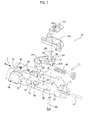
- the auxiliary safety module 22 comprises a stationary support 26, which is designed to be fixed to the wing 14 in the immediate vicinity of the vertical edge of the wing 14 opposite to the pivot axis A.
- the stationary support 26 has a base wall 28 and two side walls 30, 31 parallel to each other and which protrude from the base wall 28.
- the stationary support 26 is essentially U-shaped and is preferably formed of bent sheet metal.
- the side wall 30 of the stationary support 26 is equipped with three openings 32, 34, 36.
- the auxiliary safety module 22 comprises a slider 38, preferably made of stamped sheet metal, mounted adjacent to the base wall 28 between the two side walls 30, 31 of the stationary support 26.
- the slider 38 is movable relative to the stationary support 26 in a longitudinal direction C between a closed position and an open position.
- the slider 38 is connected to one end of a respective rod 24.
- an elastic element in compression 40 is arranged between the slider 38 and the stationary support 26, and tends to push the slider 38 towards the closed position.
- the auxiliary safety module 22 comprises a spring latch 42 movable relative to the stationary support 26 along a direction perpendicular to the longitudinal direction C between an extracted position and a retracted position.
- the spring latch 42 is guided by a pair of pins 44 fixed between the side walls 30, 31 of the stationary support 26.
- Two compression coil springs 46 are arranged coaxially to respective pins 44 and push the latch 42 toward the extracted position.
- the latch 42 has a head 48 that protrudes outwards from the stationary support 26 through the opening 32.
- the latch 42 has a body 50 provided with holes 52 through which respective pins 44 extend.
- the coil springs 46 are arranged in compression between the body 50 of the latch 42 and the wall 31 of the stationary support 26.
- the spring latch 42 is connected to the slider 38 by means of a transmission mechanism 54.
- the transmission mechanism 54 comprises a plate 56 hinged to the base wall 28 of the stationary support 26 by a pin 58.
- the plate 56 has two projecting pins 60, 62.
- the pin 60 engages an opening 64 formed in the body 50 of the latch 42.
- the pin 62 engages a slit 66 of the slider 38 elongated along a transverse direction with respect to the longitudinal direction C.
- the transmission mechanism 54 moves the spring latch 42 from the extracted position towards the retracted position against the action of the springs 46 following the movement of the slider 38 from the closed position to the open position.
- the auxiliary safety module 22 comprises a probe 68 movable relative to the stationary support 26 along a transverse direction with respect to the longitudinal direction C between an extracted position and a retracted position.
- the probe 68 has a head 70 that protrudes outwards from the stationary support 26 through the opening 34, and a body 72 having a hole 74 through which a pin 76 extends, fixed between the two side walls 30, 31 of the stationary support 26.
- a compression coil spring 78 is arranged coaxially to the pin 76 between the body 72 and the side wall 31 and pushes elastically the probe 68 towards the extracted position.
- the probe 68 has a stop pin 80, which is arranged within an opening 82 of the slider 38.
- the opening 82 is essentially L-shaped with a first branch parallel to the longitudinal direction C and a second branch perpendicular to the transverse direction C.
- the auxiliary safety module 22 comprises a hook 84 hinged to the stationary support 26 about an axis perpendicular to the longitudinal direction C by means of a pin 86.
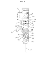
- the pin 86 extends through a hole 88 in the base wall 28 ( Figure 4 ) and through a slot 90 elongated in the longitudinal direction C of the slider 38.
- the end of the pin 86 opposite to the base wall 28 engages a bracket 92 fixed between the side walls 30, 31 of the stationary support 26.
- the hook 84 has a locking portion 94 that protrudes outwards from the stationary support 26 through the opening 36 of the side wall 30, and a base 96 having a hole 97 through which the pin 86 extends.
- the hook 84 is free to rotate about the pin 86.
- the base 96 of the hook 84 has a cam opening 98 in which a pin 100 is engaged, fixed to an anchor 102 attached to the slider 38.
- the cam opening 98 of the hook 84 is shaped in such a way that when the slider 38 is in the closed position, the hook 84 is in a locked position and when the slider 38 is in the open position, the hook 84 is rotated into an unlocked position
- the base 96 of the hook 84 has a stop surface 104 located on the opposite side of the pin 86 with respect to the locking portion 94.
- an appendix 106 of the anchor 102 comes into abutment with the stop surface 104 preventing a rotation of the hook 84 towards the unlocked position. In this way, this prevents burglary attempts that are carried out by attempting to rotate the hook 84 towards the unlocked position by acting from the external side of the door by means of thin objects inserted into the gap between the facing sides of the wing and the frame.
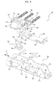
- FIGS 2 and 3 illustrate the auxiliary safety module 22 mounted on the wing 14, in the locked and unlocked conditions of the wing, respectively.
- the auxiliary safety module 22 faces three strikers 108, 110, 114 fixed to the frame 12.
- the first striker 108 cooperates with the spring latch 42
- the second striker 110 cooperates with the probe 68
- the third striker 114 has a seat into which the blocking portion 94 of the hook 84 is inserted in the locked position.
- the head 70 of the probe 68 interferes with the counterpart 110.
- the probe 68 is pushed toward its retracted position.
- the stop pin 80 disengages the stop surface 118 and the slider 38 is free to return towards the closed position under the thrust of the elastic element 40.
- the return of the slider 38 into the closed position returns the hook 84 to the locked position and the spring latch 42 into the extracted position.
Landscapes
- Engineering & Computer Science (AREA)
- Mechanical Engineering (AREA)
- Business, Economics & Management (AREA)
- Emergency Management (AREA)
- Lock And Its Accessories (AREA)
- Closing And Opening Devices For Wings, And Checks For Wings (AREA)
- Push-Button Switches (AREA)
- Arrangement Of Elements, Cooling, Sealing, Or The Like Of Lighting Devices (AREA)
Applications Claiming Priority (1)
| Application Number | Priority Date | Filing Date | Title |
|---|---|---|---|
| IT000142A ITTO20130142A1 (it) | 2013-02-21 | 2013-02-21 | Modulo di sicurezza ausiliario per porte munite di un dispositivo di apertura antipanico |
Publications (1)
| Publication Number | Publication Date |
|---|---|
| EP2770142A1 true EP2770142A1 (en) | 2014-08-27 |
Family
ID=48050166
Family Applications (1)
| Application Number | Title | Priority Date | Filing Date |
|---|---|---|---|
| EP20140152424 Withdrawn EP2770142A1 (en) | 2013-02-21 | 2014-01-24 | Auxiliary safety module for doors fitted with an anti-panic opening device |
Country Status (6)
| Country | Link |
|---|---|
| US (1) | US20140232119A1 (it) |
| EP (1) | EP2770142A1 (it) |
| CN (1) | CN104005626A (it) |
| IL (1) | IL230795A0 (it) |
| IT (1) | ITTO20130142A1 (it) |
| RU (1) | RU2014105544A (it) |
Cited By (1)
| Publication number | Priority date | Publication date | Assignee | Title |
|---|---|---|---|---|
| AU2016204675B2 (en) * | 2015-07-15 | 2021-09-30 | Azuma Design Pty Limited | A latch assembly |
Citations (3)
| Publication number | Priority date | Publication date | Assignee | Title |
|---|---|---|---|---|
| EP1158126A1 (de) * | 1999-09-25 | 2001-11-28 | KARL FLIETHER GmbH & Co. | Schloss |
| EP1887170A1 (en) | 2006-08-09 | 2008-02-13 | SAVIO S.p.A. | Auxiliary safety module for doors provided with anti-panic opening device |
| DE202011103779U1 (de) * | 2011-07-06 | 2012-10-15 | Maco Technologie Gmbh | Schloss |
Family Cites Families (13)
| Publication number | Priority date | Publication date | Assignee | Title |
|---|---|---|---|---|
| US2505190A (en) * | 1948-03-06 | 1950-04-25 | Sargent & Co | Exit lock |
| US3345099A (en) * | 1965-09-14 | 1967-10-03 | Sargent & Greenleaf | Panic exit device |
| FR2814190B1 (fr) * | 2000-09-21 | 2003-08-29 | Jpm Sa | Mecanisme de manoeuvre de porte |
| ITTO20020281A1 (it) * | 2002-03-29 | 2003-09-29 | Savio Spa | ,,sistema di apertura antipanico per porte,,. |
| CN2545309Y (zh) * | 2002-05-15 | 2003-04-16 | 李坤林 | 具有紧急开启装置的防火门推锁 |
| FR2861789B1 (fr) * | 2003-11-05 | 2006-01-27 | Vachette Sa | Serrure anti-panique multipoint reversible |
| DE602005007609D1 (de) * | 2005-09-30 | 2008-07-31 | Savio Spa | Steuerungssystem für Paniktüren |
| EP1857087B1 (en) * | 2006-05-16 | 2010-12-22 | MG2 S.r.l. | Machine for filling containers with at least one granular product |
| US7887107B2 (en) * | 2008-01-31 | 2011-02-15 | I-Tek Metal Mfg. Co., Ltd. | Universal assembly for top and bottom latches |
| US8042843B2 (en) * | 2008-04-25 | 2011-10-25 | I-Tek Metal Mfg. Co., Ltd. | Adjustable driving mechanism for panic door lock |
| ES2363896B1 (es) * | 2008-08-08 | 2012-06-22 | José Ramón Baragaño González | Sistema antipánico deslizante y modular de mínimos desplazamientos aplicable a puertas de emergencia. |
| US8029027B2 (en) * | 2008-08-20 | 2011-10-04 | I-Tek Metal Mfg. Co., Ltd. | Latch device for panic door lock with anti-picking function |
| GB2466962A (en) * | 2009-01-15 | 2010-07-21 | Securistyle Ltd | A locking mechanism with various control arrangements |
-
2013
- 2013-02-21 IT IT000142A patent/ITTO20130142A1/it unknown
-
2014
- 2014-01-24 EP EP20140152424 patent/EP2770142A1/en not_active Withdrawn
- 2014-02-03 IL IL230795A patent/IL230795A0/en unknown
- 2014-02-17 RU RU2014105544/12A patent/RU2014105544A/ru not_active Application Discontinuation
- 2014-02-17 US US14/182,191 patent/US20140232119A1/en not_active Abandoned
- 2014-02-21 CN CN201410059467.3A patent/CN104005626A/zh active Pending
Patent Citations (3)
| Publication number | Priority date | Publication date | Assignee | Title |
|---|---|---|---|---|
| EP1158126A1 (de) * | 1999-09-25 | 2001-11-28 | KARL FLIETHER GmbH & Co. | Schloss |
| EP1887170A1 (en) | 2006-08-09 | 2008-02-13 | SAVIO S.p.A. | Auxiliary safety module for doors provided with anti-panic opening device |
| DE202011103779U1 (de) * | 2011-07-06 | 2012-10-15 | Maco Technologie Gmbh | Schloss |
Cited By (1)
| Publication number | Priority date | Publication date | Assignee | Title |
|---|---|---|---|---|
| AU2016204675B2 (en) * | 2015-07-15 | 2021-09-30 | Azuma Design Pty Limited | A latch assembly |
Also Published As
| Publication number | Publication date |
|---|---|
| IL230795A0 (en) | 2014-08-31 |
| CN104005626A (zh) | 2014-08-27 |
| RU2014105544A (ru) | 2015-08-27 |
| ITTO20130142A1 (it) | 2014-08-22 |
| US20140232119A1 (en) | 2014-08-21 |
Similar Documents
| Publication | Publication Date | Title |
|---|---|---|
| US8726572B2 (en) | Window restrictor | |
| US7942027B1 (en) | Door latch | |
| EP2935741B1 (en) | Latch mechanism | |
| US9890570B2 (en) | Sliding door or window latch | |
| AU2003278645A1 (en) | A self-latching device | |
| CN104718339A (zh) | 被动门锁机构 | |
| US20110163555A1 (en) | Sliding Door and Window Locks | |
| RU127803U1 (ru) | Замок комбинированный | |
| EP2525027A2 (en) | Privacy latch | |
| US20150368958A1 (en) | Electromagnetic Door Opener | |
| US20140232119A1 (en) | Auxiliary safety module for doors fitted with an anti-panic opening device | |
| KR101256040B1 (ko) | 슬라이딩 도어 핸들 | |
| US20070001469A1 (en) | Retractable strike for panic locks | |
| US20130119678A1 (en) | Multi-point lock assembly | |
| US6174003B1 (en) | Fastening assembly comprising bolt and keeper | |
| RU2596945C2 (ru) | Отпирающее устройство эвакуационного выхода со скользящей защелкой | |
| EP1770232B1 (en) | Anti-panic control device for doors | |
| AU2008200924B2 (en) | Improvements in locks | |
| AU2009201675B2 (en) | Improvements in Locks | |
| IE54456B1 (en) | Locks | |
| CN203879197U (zh) | 一种具有前后门互锁机构的双开门保险柜 | |
| EP2569497B1 (en) | Door having a device for openable latching of the door | |
| RU98032U1 (ru) | Ручка-защелка | |
| JPH0241249Y2 (it) | ||
| EP0725879A1 (en) | Automatically latching bolt |
Legal Events
| Date | Code | Title | Description |
|---|---|---|---|
| PUAI | Public reference made under article 153(3) epc to a published international application that has entered the european phase |
Free format text: ORIGINAL CODE: 0009012 |
|
| 17P | Request for examination filed |
Effective date: 20140124 |
|
| AK | Designated contracting states |
Kind code of ref document: A1 Designated state(s): AL AT BE BG CH CY CZ DE DK EE ES FI FR GB GR HR HU IE IS IT LI LT LU LV MC MK MT NL NO PL PT RO RS SE SI SK SM TR |
|
| AX | Request for extension of the european patent |
Extension state: BA ME |
|
| STAA | Information on the status of an ep patent application or granted ep patent |
Free format text: STATUS: THE APPLICATION IS DEEMED TO BE WITHDRAWN |
|
| 18D | Application deemed to be withdrawn |
Effective date: 20150228 |