EP2770152A1 - Étanchiésation et dispositif d'étanchiété pour feuilles d'une porte et d'une fenêtre - Google Patents
Étanchiésation et dispositif d'étanchiété pour feuilles d'une porte et d'une fenêtre Download PDFInfo
- Publication number
- EP2770152A1 EP2770152A1 EP14000531.5A EP14000531A EP2770152A1 EP 2770152 A1 EP2770152 A1 EP 2770152A1 EP 14000531 A EP14000531 A EP 14000531A EP 2770152 A1 EP2770152 A1 EP 2770152A1
- Authority
- EP
- European Patent Office
- Prior art keywords
- seal
- floor
- door
- threshold
- lip
- Prior art date
- Legal status (The legal status is an assumption and is not a legal conclusion. Google has not performed a legal analysis and makes no representation as to the accuracy of the status listed.)
- Granted
Links
Images


Classifications
-
- E—FIXED CONSTRUCTIONS
- E06—DOORS, WINDOWS, SHUTTERS, OR ROLLER BLINDS IN GENERAL; LADDERS
- E06B—FIXED OR MOVABLE CLOSURES FOR OPENINGS IN BUILDINGS, VEHICLES, FENCES OR LIKE ENCLOSURES IN GENERAL, e.g. DOORS, WINDOWS, BLINDS, GATES
- E06B7/00—Special arrangements or measures in connection with doors or windows
- E06B7/16—Sealing arrangements on wings or parts co-operating with the wings
- E06B7/18—Sealing arrangements on wings or parts co-operating with the wings by means of movable edgings, e.g. draught sealings additionally used for bolting, e.g. by spring force or with operating lever
- E06B7/20—Sealing arrangements on wings or parts co-operating with the wings by means of movable edgings, e.g. draught sealings additionally used for bolting, e.g. by spring force or with operating lever automatically withdrawn when the wing is opened, e.g. by means of magnetic attraction, a pin or an inclined surface, especially for sills
- E06B7/215—Sealing arrangements on wings or parts co-operating with the wings by means of movable edgings, e.g. draught sealings additionally used for bolting, e.g. by spring force or with operating lever automatically withdrawn when the wing is opened, e.g. by means of magnetic attraction, a pin or an inclined surface, especially for sills with sealing strip being moved to a retracted position by elastic means, e.g. springs
-
- E—FIXED CONSTRUCTIONS
- E06—DOORS, WINDOWS, SHUTTERS, OR ROLLER BLINDS IN GENERAL; LADDERS
- E06B—FIXED OR MOVABLE CLOSURES FOR OPENINGS IN BUILDINGS, VEHICLES, FENCES OR LIKE ENCLOSURES IN GENERAL, e.g. DOORS, WINDOWS, BLINDS, GATES
- E06B7/00—Special arrangements or measures in connection with doors or windows
- E06B7/16—Sealing arrangements on wings or parts co-operating with the wings
- E06B7/22—Sealing arrangements on wings or parts co-operating with the wings by means of elastic edgings, e.g. elastic rubber tubes; by means of resilient edgings, e.g. felt or plush strips, resilient metal strips
- E06B7/23—Plastic, sponge rubber, or like strips or tubes
- E06B7/2305—Plastic, sponge rubber, or like strips or tubes with an integrally formed part for fixing the edging
- E06B7/2312—Plastic, sponge rubber, or like strips or tubes with an integrally formed part for fixing the edging with two or more sealing-lines or -planes between the wing and part co-operating with the wing
-
- E—FIXED CONSTRUCTIONS
- E06—DOORS, WINDOWS, SHUTTERS, OR ROLLER BLINDS IN GENERAL; LADDERS
- E06B—FIXED OR MOVABLE CLOSURES FOR OPENINGS IN BUILDINGS, VEHICLES, FENCES OR LIKE ENCLOSURES IN GENERAL, e.g. DOORS, WINDOWS, BLINDS, GATES
- E06B7/00—Special arrangements or measures in connection with doors or windows
- E06B7/16—Sealing arrangements on wings or parts co-operating with the wings
- E06B7/22—Sealing arrangements on wings or parts co-operating with the wings by means of elastic edgings, e.g. elastic rubber tubes; by means of resilient edgings, e.g. felt or plush strips, resilient metal strips
- E06B7/23—Plastic, sponge rubber, or like strips or tubes
- E06B7/2316—Plastic, sponge rubber, or like strips or tubes used as a seal between the floor and the wing
Definitions
- the present invention generally finds application in the field of heat and sound insulating devices for doors and windows, and particularly relates to a seal for door or window leaves.
- the invention also relates to a sealing device for door and window leaves which incorporates such seal.
- Seals are known to be used in door and window leaves for closing off any gap occurring between the leaf and either the floor or the threshold.
- insulating seals are generally adapted to be applied to the upper and/or lower edges of the leaf.
- these seals are typically applied to the lower edges of the doors to prevent the passage of air through the gap and enhance heat and sound insulation in the environment.
- insulating seals are often designed to interact with appropriate actuator means which are adapted to cause vertical translation thereof, as the leaf is opened and closed.
- actuator means keep the seal away from the floor as the leaf is opened and cause the seal to contact the floor when the leaf is closed.
- a strong need in the art is that of providing seals for door and window leaves that ensure high insulation even when they have to close off gaps with irregular or indented profiles.
- seals for door or window leaves have been provided, whose sealing edge is specially designed to fit the irregularities in the floor or the threshold.
- EP1905938 discloses an insulating seal for doors comprising a rail that is designed to fit into a longitudinal channel formed in the lower edge of the door, and a longitudinal sealing member held within the rail, and adapted to close off the gap between the floor and the door edge.
- the sealing member is flexible and has one or more continuous downwardly extending lip projections with respective free end edges designed to contact the floor or the threshold.
- the relatively small thickness of the lip projections allows the end edge to fit the profile of the floor or the threshold even when the latter are uneven or irregular.
- a first drawback of this arrangement is that the continuous end edge of the lip projection cannot fully conform to the profile of any type of floor or threshold.
- the sealing effect of the lip projection is considerably reduced when the floor profiles to be insulated comprise tile joints extending to great lengths, of having particularly deep concavities or convexities.
- a further drawback of this arrangement is that extended use of the seal may lead to a permanent alteration of the shape of the lip projections.
- the object of the present invention is to obviate the above drawbacks, by providing a seal for door and window leaves that is highly efficient and relatively cost-effective.
- a particular object of the present invention is to provide a seal for door and window leaves that has high insulation and soundproofing properties irrespective of floor or threshold conformations.
- a further object of the present invention is to provide a seal for door and window leaves that provides high and substantially consistent efficiency.
- Another object of the present invention is to provide a seal for door and window leaves that is easily replaceable when worn or damaged.
- a seal for doors and windows particularly for hinged doors, sliding doors, windows or frames, comprising a profile made of a flexible material, which is designed to be applied to the lower edge of a door or window leaf, said profile having an elongate connecting portion with a longitudinal axis from which at least one lower lip projection extends to interact with the floor or the threshold of the leaf.
- the seal is characterized in that said at least one lip projection has a plurality of substantially transverse cuts uniformly arranged along the entire longitudinal extent of the projection, and defining a plurality of independent flexible segments, which are adapted to allow the seal to fit the irregularities of the floor or the threshold with low friction.
- the invention relates to a sealing device for door and window leaves as defined in claim 10.
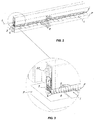
- a seal for door and window leaves generally designated by numeral 1, which is designed to be applied to a door or a window S to act as a door bottom seal for weather proofing and for improved heat and sound insulation in the environment.
- the seal 1 may be advantageously applied to an end edge B of a leaf A of a door or window S, to provide a sealing effect at a gap F with the floor P or a threshold that may have shape irregularities, due to the presence of joints K between tiles T, or flatness or tilt errors.
- seal 1 may be used to provide insulation and lateral protection in sliding doors Z or may be alternatively used to provide a sealing action on windows or other frames.
- the seal 1 of the invention comprises a profile 2 made of a flexible material, which is designed to be applied to the lower edge B of the leaf A, and has an elongate connecting portion 3 defining a longitudinal axis L, from which at least one lower projection 4 extends to interact with the floor P or the threshold of the leaf A.
- the profile 2 may be made of a flexible material selected from the group comprising elastomers and polymeric materials.
- the profile 2 may be as long as or longer than the leaf A of the door or window S, such as to partially or entirely close off the gap F.
- the lip projection 4 may extend downwards from the upper portion 3 along a substantially vertical transverse direction V.
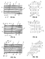
- the lip projection 4 has a plurality of substantially transverse cuts 5 uniformly arranged along the entire longitudinal extent 14 of the projection 4, thereby defining a plurality of independent lip segments 6, which are adapted to impart greater flexibility to the seal 1 and to allow it to fit the irregularities of the floor P or the threshold with low friction.
- each segment 6 may be elastically deformed in the vertical direction to fit the local profile of the floor P or the threshold, independently of the other profiles.
- the lip projections 4 may have equal longitudinal extents 14.
- the cuts 5, as best shown in the figures, may be substantially vertical and perpendicular to the longitudinal axis L.
- the cuts 5 may be longitudinally arranged with a substantially constant pitch p, to define segments 6 having substantially equal longitudinal extents.
- the cuts 5 may be arranged with a pitch p ranging from 1 mm to 10 mm, preferably of about 3 mm.
- the cuts 5 may have an extent w corresponding to part of the maximum height h of the lip projection 4 and the flexible segments 6 may be connected together at the remaining part of the maximum height h of at least one lip projection 4.
- cuts 5 may have equal transverse extents w.
- the cuts 5 may be arranged with a variable pitch p and have different transverse extents w to define segments 6 of different sizes.
- the elongate body 3 may comprise a central tubular body 7 whose bottom face 8 is designed to contact the floor P or the threshold.
- the seal 1 may have a pair of lip projections, referenced 4, 4' in the figures, extending downwards from the sides of the central tubular body 7.
- Each lip projection 4, 4' may have a respective plurality of independent segments 6 which are designed to contact the floor P or threshold.
- the seal 1 will provide an overall sealing action, resulting from the superimposed sealing actions of the tubular body 7 and each of the lip projections 4, 4' on the floor P or threshold.
- the tubular body 7 may have a plurality of additional substantially transverse cuts 9, not shown, similar to those of the lip projections 4, 4'.
- Cuts 9 are adapted to define a plurality of independent longitudinal tubular portions 10 in the tubular body 7, for helping the tubular body to fit the irregularities of the floor P or the threshold.
- tubular portions 10 may undergo differentiated vertical compression to fit the irregularities and inclinations in the floor P or the threshold.
- the seal 1 may comprise a plurality of substantially parallel lip projections 4, extending downwards from the connecting portion 3.
- the lip projections 4 may be composed of respective pluralities of lip segments 6, adapted to contact the floor P or threshold.
- the overall sealing action of the seal 1 results from the sum of the sealing actions of the individual lip projections 4 on the floor P or threshold.
- the lip projections 4 may have differentiated heights f for selective thereof with the floor P or threshold, upon downward translation of the seal 1, occurring as the leaf A is being closed.
- the corresponding cuts 5 of the individual lip projections 4 may lie on substantially vertical and longitudinally staggered planes n.
- the cuts 5 may lie on planes n perpendicular to the longitudinal axis L.
- Such arrangement of the cuts provides respective sequences of segments 13 aligned in respective horizontal directions X, perpendicular to the longitudinal axis L.
- the cuts 5 may lie on planes ⁇ perpendicular to the longitudinal axis L, such that the lip segments 6 of the individual projections 4 may be arranged in staggered relationship to respective horizontal directions X perpendicular to the longitudinal axis L, as schematically shown in FIG. 9b .
- the cuts 5 may lie on planes ⁇ that are substantially vertical and inclined to the longitudinal axis L, at a predetermined inclination angle ⁇ .
- Such arrangement of the cuts 5, as schematically shown in FIG. 10b provides respective sequences 13 of segments 6 aligned in respective directions Y inclined to the longitudinal axis L at said inclination angle ⁇ .
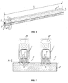
- the invention also relates to a sealing device 14 for leaves A of doors and windows S, as best shown in FIGS. 11 and 12 , comprising an elongate support 15, which is adapted to fit into a channel C formed in the lower edge B of the leaf A.
- the elongate support 15 holds therein a weather and sound proofing type of seal 1 as described above.
- the seal 1 comprises at least one lip projection 4 having a plurality of substantially transverse cuts 5 uniformly arranged along the entire longitudinal extent of the projection 4, thereby defining a plurality of independent lip segments 6, which are adapted to allow the seal 1 to fit the local irregularities of the floor or the threshold with low friction.
- the seal 1 may comprise a plurality of longitudinal lip projections 4 in substantially uniformly staggered arrangement, as shown in FIG. 11 , or may comprise a tubular body 7 and a pair of lop projections 4, 4', as shown in FIG. 12 .
- the elongate support 15 may be substantially U-shaped, to define an inner housing 16 for the seal 1.
- the latter comprises a substantially longitudinal elongate connecting portion 3, which has a pair of transverse arms 19, 20 at the ends 17, 18, for interaction with the inner wall 21 of the compartment 16 and easier friction fit of the seal 1 therewith.
- the device 14 may comprise actuator means 22, which are located within the support 15 and act upon the seal 1 to cause vertical translation t thereof, and compression of the lip projection 4 against the floor P or threshold.
- the actuator means 22 may be designed to cause vertical translation t of the seal from an inoperative position at least partially retracted in the compartment 16 to an operative position at least partially projecting from the compartment 16.
- the lip projection 4 may be spaced from the floor P or the threshold for the leaf A of the door or window S to be opened.
- the lip projection 4 may be compressed onto the floor P or the threshold to provide weather and sound proofing.
- the operative position may be assumed when the user causes the leaf A of the door or window S to close.
- the actuator means 22 may comprise a substantially U-shaped longitudinal interface element 23 having an outer edge 24 at least partially in contact with the seal 1.
- the actuator means 23 may comprise a pushing member, not shown, which is vertically movable and adapted to interact with the inner edge 25 of the interface element 23 or with the upper wall 26 of the seal to cause translation t thereof between the inoperative position and the operating position.
- the seal 1 may be stably connected with the interface element 23 through appropriate mutual coupling means 27.
- the mutual coupling means 27 may be of interlocking type and may comprise a first coupling member 28 formed in the connecting portion 3 of the seal 1 and a second coupling member 29, whose shape is substantially complementary to that of the first coupling member 28, formed in the outer edge 24 of the interface element 23.
- interlocking means 27 will afford very quick and simple removal or replacement of the seal 1 of the device 14.
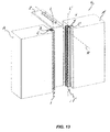
- At least one seal of the invention preferably a pair of seals 1, 1' may be applied to the side leaves A, A' of a sliding door Z for lateral protection thereof and for providing weather proofing and improving heat and sound insulation in the environment.
- the seals 1, 1' may have a specially shaped connecting portion 3, 3', which is designed to slidably fit into dedicated channels C, C' formed on the mutually facing edges of the leaves A, A'.
- the lip portions 4 of the seals 1, 1' may extend in longitudinal directions L, L' substantially orthogonal to the sliding direction R of the door Z.
- seal and sealing device of this invention are susceptible to a number of changes or variants, within the inventive concept disclosed in the annexed claims. All the details thereof may be replaced by other technically equivalent parts, and the materials may vary depending on different needs, without departure from the scope of the invention.
Landscapes
- Engineering & Computer Science (AREA)
- Civil Engineering (AREA)
- Structural Engineering (AREA)
- Specific Sealing Or Ventilating Devices For Doors And Windows (AREA)
- Gasket Seals (AREA)
Applications Claiming Priority (1)
| Application Number | Priority Date | Filing Date | Title |
|---|---|---|---|
| IT000037A ITVI20130037A1 (it) | 2013-02-20 | 2013-02-20 | Guarnizione e dispositivo di tenuta per ante di porte e serramenti |
Publications (2)
| Publication Number | Publication Date |
|---|---|
| EP2770152A1 true EP2770152A1 (fr) | 2014-08-27 |
| EP2770152B1 EP2770152B1 (fr) | 2016-01-20 |
Family
ID=48050181
Family Applications (1)
| Application Number | Title | Priority Date | Filing Date |
|---|---|---|---|
| EP14000531.5A Active EP2770152B1 (fr) | 2013-02-20 | 2014-02-14 | Joint d'étanchéité et dispositif d'étanchéité d'un vantail de porte ou de fenêtre |
Country Status (2)
| Country | Link |
|---|---|
| EP (1) | EP2770152B1 (fr) |
| IT (1) | ITVI20130037A1 (fr) |
Cited By (4)
| Publication number | Priority date | Publication date | Assignee | Title |
|---|---|---|---|---|
| GB2541064A (en) * | 2015-05-13 | 2017-02-08 | Lorient Polyprod Ltd | A door seal, a seal portion and a kit |
| CN107709690A (zh) * | 2015-07-01 | 2018-02-16 | 普兰特Gdz股份公司 | 下降密封装置 |
| CN110203287A (zh) * | 2019-03-14 | 2019-09-06 | 苏州同捷汽车工程技术股份有限公司 | 一种车身地板横梁与门槛梁连接结构 |
| CN112124598A (zh) * | 2019-06-25 | 2020-12-25 | 波音公司 | 用于密封飞机的冷藏厨房的系统和方法 |
Citations (4)
| Publication number | Priority date | Publication date | Assignee | Title |
|---|---|---|---|---|
| EP1905938A2 (fr) | 2006-09-19 | 2008-04-02 | Planet GDZ AG | Joint de porte |
| EP1967684A2 (fr) * | 2007-03-06 | 2008-09-10 | DEVENTER PROFILE GmbH & Co. KG | Profil d'étanchéité en élastomère pour joint de seuil de porte |
| DE202012007885U1 (de) * | 2012-08-20 | 2012-10-25 | Rundum Dicht Krystyna Doll Kg | Quadrodichtung für Holzfenster und Holztüren mit Nut |
| GB2490408A (en) * | 2011-04-21 | 2012-10-31 | Raven Products Pty Ltd | A door seal with bristles and a temperature resistant barrier fin |
-
2013
- 2013-02-20 IT IT000037A patent/ITVI20130037A1/it unknown
-
2014
- 2014-02-14 EP EP14000531.5A patent/EP2770152B1/fr active Active
Patent Citations (4)
| Publication number | Priority date | Publication date | Assignee | Title |
|---|---|---|---|---|
| EP1905938A2 (fr) | 2006-09-19 | 2008-04-02 | Planet GDZ AG | Joint de porte |
| EP1967684A2 (fr) * | 2007-03-06 | 2008-09-10 | DEVENTER PROFILE GmbH & Co. KG | Profil d'étanchéité en élastomère pour joint de seuil de porte |
| GB2490408A (en) * | 2011-04-21 | 2012-10-31 | Raven Products Pty Ltd | A door seal with bristles and a temperature resistant barrier fin |
| DE202012007885U1 (de) * | 2012-08-20 | 2012-10-25 | Rundum Dicht Krystyna Doll Kg | Quadrodichtung für Holzfenster und Holztüren mit Nut |
Cited By (7)
| Publication number | Priority date | Publication date | Assignee | Title |
|---|---|---|---|---|
| GB2541064A (en) * | 2015-05-13 | 2017-02-08 | Lorient Polyprod Ltd | A door seal, a seal portion and a kit |
| GB2541064B (en) * | 2015-05-13 | 2021-06-16 | Assa Abloy Ltd | A door seal, a seal portion and a kit |
| CN107709690A (zh) * | 2015-07-01 | 2018-02-16 | 普兰特Gdz股份公司 | 下降密封装置 |
| CN110203287A (zh) * | 2019-03-14 | 2019-09-06 | 苏州同捷汽车工程技术股份有限公司 | 一种车身地板横梁与门槛梁连接结构 |
| CN112124598A (zh) * | 2019-06-25 | 2020-12-25 | 波音公司 | 用于密封飞机的冷藏厨房的系统和方法 |
| EP3757007A1 (fr) * | 2019-06-25 | 2020-12-30 | The Boeing Company | Systèmes et procédés permettant de sceller un compartiment d'office réfrigéré d'un aéronef |
| US11525622B2 (en) | 2019-06-25 | 2022-12-13 | The Boeing Company | Systems and methods for sealing a refrigerated galley of an aircraft |
Also Published As
| Publication number | Publication date |
|---|---|
| EP2770152B1 (fr) | 2016-01-20 |
| ITVI20130037A1 (it) | 2014-08-21 |
Similar Documents
| Publication | Publication Date | Title |
|---|---|---|
| EP2770152B1 (fr) | Joint d'étanchéité et dispositif d'étanchéité d'un vantail de porte ou de fenêtre | |
| CA2928085C (fr) | Espaceur d'etancheisation multicouche destine aux composantes de passage d'entree | |
| AU2015340757B2 (en) | Sealing device | |
| CA2859183C (fr) | Elargisseur de seuil a pression pour seuils | |
| US9562387B2 (en) | Door bottom system for an entryway system | |
| US20050086868A1 (en) | Sealing assembly for doors and other closures | |
| KR102431616B1 (ko) | 커버 부재를 가지는 슬라이딩 벽 장치 | |
| JP6570838B2 (ja) | 防水シャッター | |
| JP6603515B2 (ja) | オーバーヘッドドア | |
| KR20140036441A (ko) | 슬라이딩 창호용 필링피스 | |
| KR101538499B1 (ko) | 안전창의 풍지판 장치 | |
| KR200478715Y1 (ko) | 미닫이식 창호시스템 | |
| KR101404706B1 (ko) | 창호용 필링피스 | |
| KR101462480B1 (ko) | 도어 틈새 막음장치 | |
| JP2018524500A (ja) | ドロップダウンシール | |
| KR20130118136A (ko) | 문턱없는 도어의 차단구조 | |
| KR102091982B1 (ko) | 창호프레임 틈새 밀폐용 기구 | |
| CN101835667A (zh) | 滑门 | |
| US20240110437A1 (en) | Under Door Seal | |
| JP2016079770A (ja) | 防水板 | |
| CN105089441A (zh) | 一种密封推拉窗 | |
| KR102551600B1 (ko) | 차양 구조물용 몰딩바 | |
| EP3473795B1 (fr) | Système anti-infiltration d'eau pour un cadre de porte | |
| US7159362B2 (en) | Shutter mounting adjuster | |
| KR200465825Y1 (ko) | 방풍 및 방음 기능이 구비된 창문구조 |
Legal Events
| Date | Code | Title | Description |
|---|---|---|---|
| PUAI | Public reference made under article 153(3) epc to a published international application that has entered the european phase |
Free format text: ORIGINAL CODE: 0009012 |
|
| 17P | Request for examination filed |
Effective date: 20140214 |
|
| AK | Designated contracting states |
Kind code of ref document: A1 Designated state(s): AL AT BE BG CH CY CZ DE DK EE ES FI FR GB GR HR HU IE IS IT LI LT LU LV MC MK MT NL NO PL PT RO RS SE SI SK SM TR |
|
| AX | Request for extension of the european patent |
Extension state: BA ME |
|
| R17P | Request for examination filed (corrected) |
Effective date: 20150223 |
|
| RBV | Designated contracting states (corrected) |
Designated state(s): AL AT BE BG CH CY CZ DE DK EE ES FI FR GB GR HR HU IE IS IT LI LT LU LV MC MK MT NL NO PL PT RO RS SE SI SK SM TR |
|
| GRAP | Despatch of communication of intention to grant a patent |
Free format text: ORIGINAL CODE: EPIDOSNIGR1 |
|
| RIC1 | Information provided on ipc code assigned before grant |
Ipc: E06B 7/215 20060101ALI20150626BHEP Ipc: E06B 7/23 20060101AFI20150626BHEP |
|
| INTG | Intention to grant announced |
Effective date: 20150724 |
|
| GRAS | Grant fee paid |
Free format text: ORIGINAL CODE: EPIDOSNIGR3 |
|
| GRAA | (expected) grant |
Free format text: ORIGINAL CODE: 0009210 |
|
| AK | Designated contracting states |
Kind code of ref document: B1 Designated state(s): AL AT BE BG CH CY CZ DE DK EE ES FI FR GB GR HR HU IE IS IT LI LT LU LV MC MK MT NL NO PL PT RO RS SE SI SK SM TR |
|
| REG | Reference to a national code |
Ref country code: GB Ref legal event code: FG4D |
|
| REG | Reference to a national code |
Ref country code: CH Ref legal event code: EP |
|
| REG | Reference to a national code |
Ref country code: IE Ref legal event code: FG4D |
|
| REG | Reference to a national code |
Ref country code: AT Ref legal event code: REF Ref document number: 771810 Country of ref document: AT Kind code of ref document: T Effective date: 20160215 |
|
| REG | Reference to a national code |
Ref country code: DE Ref legal event code: R096 Ref document number: 602014000741 Country of ref document: DE |
|
| REG | Reference to a national code |
Ref country code: FR Ref legal event code: PLFP Year of fee payment: 3 |
|
| REG | Reference to a national code |
Ref country code: LT Ref legal event code: MG4D Ref country code: NL Ref legal event code: MP Effective date: 20160120 |
|
| PG25 | Lapsed in a contracting state [announced via postgrant information from national office to epo] |
Ref country code: BE Free format text: LAPSE BECAUSE OF NON-PAYMENT OF DUE FEES Effective date: 20160229 |
|
| REG | Reference to a national code |
Ref country code: AT Ref legal event code: MK05 Ref document number: 771810 Country of ref document: AT Kind code of ref document: T Effective date: 20160120 |
|
| PG25 | Lapsed in a contracting state [announced via postgrant information from national office to epo] |
Ref country code: NL Free format text: LAPSE BECAUSE OF FAILURE TO SUBMIT A TRANSLATION OF THE DESCRIPTION OR TO PAY THE FEE WITHIN THE PRESCRIBED TIME-LIMIT Effective date: 20160120 |
|
| PG25 | Lapsed in a contracting state [announced via postgrant information from national office to epo] |
Ref country code: FI Free format text: LAPSE BECAUSE OF FAILURE TO SUBMIT A TRANSLATION OF THE DESCRIPTION OR TO PAY THE FEE WITHIN THE PRESCRIBED TIME-LIMIT Effective date: 20160120 Ref country code: NO Free format text: LAPSE BECAUSE OF FAILURE TO SUBMIT A TRANSLATION OF THE DESCRIPTION OR TO PAY THE FEE WITHIN THE PRESCRIBED TIME-LIMIT Effective date: 20160420 Ref country code: HR Free format text: LAPSE BECAUSE OF FAILURE TO SUBMIT A TRANSLATION OF THE DESCRIPTION OR TO PAY THE FEE WITHIN THE PRESCRIBED TIME-LIMIT Effective date: 20160120 Ref country code: ES Free format text: LAPSE BECAUSE OF FAILURE TO SUBMIT A TRANSLATION OF THE DESCRIPTION OR TO PAY THE FEE WITHIN THE PRESCRIBED TIME-LIMIT Effective date: 20160120 Ref country code: GR Free format text: LAPSE BECAUSE OF FAILURE TO SUBMIT A TRANSLATION OF THE DESCRIPTION OR TO PAY THE FEE WITHIN THE PRESCRIBED TIME-LIMIT Effective date: 20160421 |
|
| PG25 | Lapsed in a contracting state [announced via postgrant information from national office to epo] |
Ref country code: SE Free format text: LAPSE BECAUSE OF FAILURE TO SUBMIT A TRANSLATION OF THE DESCRIPTION OR TO PAY THE FEE WITHIN THE PRESCRIBED TIME-LIMIT Effective date: 20160120 Ref country code: LT Free format text: LAPSE BECAUSE OF FAILURE TO SUBMIT A TRANSLATION OF THE DESCRIPTION OR TO PAY THE FEE WITHIN THE PRESCRIBED TIME-LIMIT Effective date: 20160120 Ref country code: IS Free format text: LAPSE BECAUSE OF FAILURE TO SUBMIT A TRANSLATION OF THE DESCRIPTION OR TO PAY THE FEE WITHIN THE PRESCRIBED TIME-LIMIT Effective date: 20160520 Ref country code: PL Free format text: LAPSE BECAUSE OF FAILURE TO SUBMIT A TRANSLATION OF THE DESCRIPTION OR TO PAY THE FEE WITHIN THE PRESCRIBED TIME-LIMIT Effective date: 20160120 Ref country code: AT Free format text: LAPSE BECAUSE OF FAILURE TO SUBMIT A TRANSLATION OF THE DESCRIPTION OR TO PAY THE FEE WITHIN THE PRESCRIBED TIME-LIMIT Effective date: 20160120 Ref country code: LV Free format text: LAPSE BECAUSE OF FAILURE TO SUBMIT A TRANSLATION OF THE DESCRIPTION OR TO PAY THE FEE WITHIN THE PRESCRIBED TIME-LIMIT Effective date: 20160120 Ref country code: PT Free format text: LAPSE BECAUSE OF FAILURE TO SUBMIT A TRANSLATION OF THE DESCRIPTION OR TO PAY THE FEE WITHIN THE PRESCRIBED TIME-LIMIT Effective date: 20160520 Ref country code: RS Free format text: LAPSE BECAUSE OF FAILURE TO SUBMIT A TRANSLATION OF THE DESCRIPTION OR TO PAY THE FEE WITHIN THE PRESCRIBED TIME-LIMIT Effective date: 20160120 |
|
| REG | Reference to a national code |
Ref country code: DE Ref legal event code: R097 Ref document number: 602014000741 Country of ref document: DE |
|
| PG25 | Lapsed in a contracting state [announced via postgrant information from national office to epo] |
Ref country code: DK Free format text: LAPSE BECAUSE OF FAILURE TO SUBMIT A TRANSLATION OF THE DESCRIPTION OR TO PAY THE FEE WITHIN THE PRESCRIBED TIME-LIMIT Effective date: 20160120 Ref country code: EE Free format text: LAPSE BECAUSE OF FAILURE TO SUBMIT A TRANSLATION OF THE DESCRIPTION OR TO PAY THE FEE WITHIN THE PRESCRIBED TIME-LIMIT Effective date: 20160120 Ref country code: MC Free format text: LAPSE BECAUSE OF FAILURE TO SUBMIT A TRANSLATION OF THE DESCRIPTION OR TO PAY THE FEE WITHIN THE PRESCRIBED TIME-LIMIT Effective date: 20160120 |
|
| PLBE | No opposition filed within time limit |
Free format text: ORIGINAL CODE: 0009261 |
|
| STAA | Information on the status of an ep patent application or granted ep patent |
Free format text: STATUS: NO OPPOSITION FILED WITHIN TIME LIMIT |
|
| PG25 | Lapsed in a contracting state [announced via postgrant information from national office to epo] |
Ref country code: RO Free format text: LAPSE BECAUSE OF FAILURE TO SUBMIT A TRANSLATION OF THE DESCRIPTION OR TO PAY THE FEE WITHIN THE PRESCRIBED TIME-LIMIT Effective date: 20160120 Ref country code: CZ Free format text: LAPSE BECAUSE OF FAILURE TO SUBMIT A TRANSLATION OF THE DESCRIPTION OR TO PAY THE FEE WITHIN THE PRESCRIBED TIME-LIMIT Effective date: 20160120 Ref country code: SM Free format text: LAPSE BECAUSE OF FAILURE TO SUBMIT A TRANSLATION OF THE DESCRIPTION OR TO PAY THE FEE WITHIN THE PRESCRIBED TIME-LIMIT Effective date: 20160120 Ref country code: SK Free format text: LAPSE BECAUSE OF FAILURE TO SUBMIT A TRANSLATION OF THE DESCRIPTION OR TO PAY THE FEE WITHIN THE PRESCRIBED TIME-LIMIT Effective date: 20160120 |
|
| 26N | No opposition filed |
Effective date: 20161021 |
|
| PG25 | Lapsed in a contracting state [announced via postgrant information from national office to epo] |
Ref country code: BE Free format text: LAPSE BECAUSE OF FAILURE TO SUBMIT A TRANSLATION OF THE DESCRIPTION OR TO PAY THE FEE WITHIN THE PRESCRIBED TIME-LIMIT Effective date: 20160120 |
|
| REG | Reference to a national code |
Ref country code: FR Ref legal event code: PLFP Year of fee payment: 4 |
|
| PG25 | Lapsed in a contracting state [announced via postgrant information from national office to epo] |
Ref country code: BG Free format text: LAPSE BECAUSE OF FAILURE TO SUBMIT A TRANSLATION OF THE DESCRIPTION OR TO PAY THE FEE WITHIN THE PRESCRIBED TIME-LIMIT Effective date: 20160420 Ref country code: SI Free format text: LAPSE BECAUSE OF FAILURE TO SUBMIT A TRANSLATION OF THE DESCRIPTION OR TO PAY THE FEE WITHIN THE PRESCRIBED TIME-LIMIT Effective date: 20160120 |
|
| PG25 | Lapsed in a contracting state [announced via postgrant information from national office to epo] |
Ref country code: MT Free format text: LAPSE BECAUSE OF FAILURE TO SUBMIT A TRANSLATION OF THE DESCRIPTION OR TO PAY THE FEE WITHIN THE PRESCRIBED TIME-LIMIT Effective date: 20160120 |
|
| REG | Reference to a national code |
Ref country code: CH Ref legal event code: PL |
|
| PG25 | Lapsed in a contracting state [announced via postgrant information from national office to epo] |
Ref country code: CH Free format text: LAPSE BECAUSE OF NON-PAYMENT OF DUE FEES Effective date: 20170228 Ref country code: LI Free format text: LAPSE BECAUSE OF NON-PAYMENT OF DUE FEES Effective date: 20170228 |
|
| REG | Reference to a national code |
Ref country code: FR Ref legal event code: PLFP Year of fee payment: 5 |
|
| PG25 | Lapsed in a contracting state [announced via postgrant information from national office to epo] |
Ref country code: HU Free format text: LAPSE BECAUSE OF FAILURE TO SUBMIT A TRANSLATION OF THE DESCRIPTION OR TO PAY THE FEE WITHIN THE PRESCRIBED TIME-LIMIT; INVALID AB INITIO Effective date: 20140214 Ref country code: CY Free format text: LAPSE BECAUSE OF FAILURE TO SUBMIT A TRANSLATION OF THE DESCRIPTION OR TO PAY THE FEE WITHIN THE PRESCRIBED TIME-LIMIT Effective date: 20160120 |
|
| PG25 | Lapsed in a contracting state [announced via postgrant information from national office to epo] |
Ref country code: TR Free format text: LAPSE BECAUSE OF FAILURE TO SUBMIT A TRANSLATION OF THE DESCRIPTION OR TO PAY THE FEE WITHIN THE PRESCRIBED TIME-LIMIT Effective date: 20160120 Ref country code: LU Free format text: LAPSE BECAUSE OF NON-PAYMENT OF DUE FEES Effective date: 20160214 Ref country code: MK Free format text: LAPSE BECAUSE OF FAILURE TO SUBMIT A TRANSLATION OF THE DESCRIPTION OR TO PAY THE FEE WITHIN THE PRESCRIBED TIME-LIMIT Effective date: 20160120 Ref country code: MT Free format text: LAPSE BECAUSE OF FAILURE TO SUBMIT A TRANSLATION OF THE DESCRIPTION OR TO PAY THE FEE WITHIN THE PRESCRIBED TIME-LIMIT Effective date: 20160229 |
|
| PG25 | Lapsed in a contracting state [announced via postgrant information from national office to epo] |
Ref country code: AL Free format text: LAPSE BECAUSE OF FAILURE TO SUBMIT A TRANSLATION OF THE DESCRIPTION OR TO PAY THE FEE WITHIN THE PRESCRIBED TIME-LIMIT Effective date: 20160120 |
|
| PGFP | Annual fee paid to national office [announced via postgrant information from national office to epo] |
Ref country code: GB Payment date: 20260223 Year of fee payment: 13 |
|
| PGFP | Annual fee paid to national office [announced via postgrant information from national office to epo] |
Ref country code: IE Payment date: 20260219 Year of fee payment: 13 Ref country code: DE Payment date: 20260220 Year of fee payment: 13 |
|
| PGFP | Annual fee paid to national office [announced via postgrant information from national office to epo] |
Ref country code: IT Payment date: 20260220 Year of fee payment: 13 |
|
| PGFP | Annual fee paid to national office [announced via postgrant information from national office to epo] |
Ref country code: FR Payment date: 20260224 Year of fee payment: 13 |