EP2770180A2 - Zweitaktverbrennungsmotor - Google Patents
Zweitaktverbrennungsmotor Download PDFInfo
- Publication number
- EP2770180A2 EP2770180A2 EP14156066.4A EP14156066A EP2770180A2 EP 2770180 A2 EP2770180 A2 EP 2770180A2 EP 14156066 A EP14156066 A EP 14156066A EP 2770180 A2 EP2770180 A2 EP 2770180A2
- Authority
- EP
- European Patent Office
- Prior art keywords
- scavenging
- port
- piston
- passage
- cylinder chamber
- Prior art date
- Legal status (The legal status is an assumption and is not a legal conclusion. Google has not performed a legal analysis and makes no representation as to the accuracy of the status listed.)
- Granted
Links
Images


Classifications
-
- F—MECHANICAL ENGINEERING; LIGHTING; HEATING; WEAPONS; BLASTING
- F02—COMBUSTION ENGINES; HOT-GAS OR COMBUSTION-PRODUCT ENGINE PLANTS
- F02B—INTERNAL-COMBUSTION PISTON ENGINES; COMBUSTION ENGINES IN GENERAL
- F02B25/00—Engines characterised by using fresh charge for scavenging cylinders
- F02B25/02—Engines characterised by using fresh charge for scavenging cylinders using unidirectional scavenging
-
- F—MECHANICAL ENGINEERING; LIGHTING; HEATING; WEAPONS; BLASTING
- F02—COMBUSTION ENGINES; HOT-GAS OR COMBUSTION-PRODUCT ENGINE PLANTS
- F02B—INTERNAL-COMBUSTION PISTON ENGINES; COMBUSTION ENGINES IN GENERAL
- F02B75/00—Other engines
- F02B75/02—Engines characterised by their cycles, e.g. six-stroke
-
- F—MECHANICAL ENGINEERING; LIGHTING; HEATING; WEAPONS; BLASTING
- F02—COMBUSTION ENGINES; HOT-GAS OR COMBUSTION-PRODUCT ENGINE PLANTS
- F02B—INTERNAL-COMBUSTION PISTON ENGINES; COMBUSTION ENGINES IN GENERAL
- F02B25/00—Engines characterised by using fresh charge for scavenging cylinders
- F02B25/14—Engines characterised by using fresh charge for scavenging cylinders using reverse-flow scavenging, e.g. with both outlet and inlet ports arranged near bottom of piston stroke
- F02B25/16—Engines characterised by using fresh charge for scavenging cylinders using reverse-flow scavenging, e.g. with both outlet and inlet ports arranged near bottom of piston stroke the charge flowing upward essentially along cylinder wall opposite the inlet ports
-
- F—MECHANICAL ENGINEERING; LIGHTING; HEATING; WEAPONS; BLASTING
- F02—COMBUSTION ENGINES; HOT-GAS OR COMBUSTION-PRODUCT ENGINE PLANTS
- F02B—INTERNAL-COMBUSTION PISTON ENGINES; COMBUSTION ENGINES IN GENERAL
- F02B33/00—Engines characterised by provision of pumps for charging or scavenging
- F02B33/02—Engines with reciprocating-piston pumps; Engines with crankcase pumps
- F02B33/04—Engines with reciprocating-piston pumps; Engines with crankcase pumps with simple crankcase pumps, i.e. with the rear face of a non-stepped working piston acting as sole pumping member in co-operation with the crankcase
-
- F—MECHANICAL ENGINEERING; LIGHTING; HEATING; WEAPONS; BLASTING
- F02—COMBUSTION ENGINES; HOT-GAS OR COMBUSTION-PRODUCT ENGINE PLANTS
- F02B—INTERNAL-COMBUSTION PISTON ENGINES; COMBUSTION ENGINES IN GENERAL
- F02B75/00—Other engines
- F02B75/02—Engines characterised by their cycles, e.g. six-stroke
- F02B2075/022—Engines characterised by their cycles, e.g. six-stroke having less than six strokes per cycle
- F02B2075/025—Engines characterised by their cycles, e.g. six-stroke having less than six strokes per cycle two
Definitions
- the present invention generally relates to a two-stroke internal combustion engine and, more particularly, to an engine of a reverse scavenging type.
- the two-stroke internal combustion engine includes a small number of components and is small in size and weight, the two-stroke internal combustion engine is applied to portable or handheld working machines such as a brush cutter, a blower, and a chain saw.
- the two-stroke internal combustion engine of this type includes a scavenging passage connected to a cylinder chamber and a crank chamber.
- the scavenging passage is open to the cylinder chamber through a scavenging port.
- the scavenging port is opened and closed by a piston.
- the cylinder chamber is defined by a piston.
- a crankshaft is housed in the crank chamber, and a reciprocating motion of the piston is converted into a rotary motion by the crankshaft.
- Patent Document No. 1 discloses a two-stroke internal combustion engine that uses fresh air for scavenging.
- the two-stroke internal combustion engine of this type is called "stratified scavenging type engine”.
- Patent Document No. 1 discloses various stratified scavenging type engines. Specifically, the stratified scavenging type engine includes a gas mixture passage and a fresh air passage as an intake system of the engine. A gas mixture passing through the gas mixture passage is introduced into the crank chamber through a gas mixture port opened and closed by a piston.
- the stratified scavenging type engine is classified into two types according to methods of introducing the fresh air into the scavenging passage.
- a first engine is an engine of a reed valve type.
- a second engine is an engine of a piston groove type.
- Patent Document No. 1 discloses the piston groove type engine.
- the reed valve type engine includes a reed valve that controls the fresh air charged in the scavenging passage.
- a position of the reed valve in the engine will be explained.
- the fresh air passage merges with the scavenging passage in an upper part of the scavenging passage, that is, in a position near the scavenging port.
- the reed valve is arranged in this merging portion.
- the reed valve type engine when the piston ascends and the pressure in the crank chamber falls, the gas mixture flows into the crank chamber through the gas mixture passage and the reed valve opens.
- the reed valve opens the fresh air is fed from the fresh air passage to the scavenging passage.
- the piston groove type engine includes a piston groove, through which the fresh air passes, on the outer circumferential surface of the piston.
- the piston groove communicates with the fresh air passage and the scavenging port.
- the fresh air is fed from the fresh air passage to the scavenging passage via the piston groove by the communication.
- the piston ascends and the pressure in the crank chamber falls, the gas mixture flows into the crank chamber through the gas mixture passage.
- the fresh air passage and the scavenging passage also communicate with each other through the piston grove, so that the fresh air flows into the scavenging passage.
- Patent Document No. 5 discloses an engine of a Schnurle type, which is a typical example of the "reverse scavenging" method.
- the Schnurle type engine disclosed in Patent Document No. 5 includes a pair of scavenging passages on the left and right when a cylinder bore is viewed in plan view. Scavenging ports of the respective scavenging passages are directed to the opposite side of exhaust ports.
- gas spouted from the scavenging port into the cylinder chamber is directed in a direction away from the exhaust port. Then, the gas collides against a wall surface of the cylinder bore located on the opposite side of the exhaust port to be reversed and directed to the exhaust port.
- the "reversed scavenging method has an effect of, for example, suppressing so-called “blow-by" in which the gas mixture passes through the cylinder chamber without staying therein and is emitted to the outside from the exhaust port in a scavenging stroke.
- Patent Document No. 5 discloses an invention having an object of reducing a blow-by loss of a gas mixture.
- the invention relates to a scavenging passage and proposes shaping of a wall surface of the scavenging passage into a specific shape.
- the invention proposes a structure concerning a wall surface of a scavenging passage portion adjacent to a scavenging port. More specifically, when a cylinder chamber is viewed in plan view, according to the invention of Patent Document No. 5, it is proposed that a wall surface on a side close to an exhaust port in the wall surface of the scavenging passage portion adjacent to the scavenging port is composed of an inclined surface.
- a flowing direction of a scavenging gas passing through the scavenging passage is directed to the opposite side of the exhaust port near the scavenging port by the inclined surface. Consequently, a flow of the scavenging gas spouting from the scavenging port to the cylinder chamber is directed to a direction away from the exhaust port.
- blow-by loss of the gas mixture is an important technical problem considered to be a fate of the two-stroke internal combustion engine. Improvement of the blow-by loss of the gas mixture is directly linked to improvement of a fuel consumption ratio and improvement of emission. In particular, the recent environmental problem requests further improvement of the blow-by loss.
- the inventors propose the present invention because the inventors were able to obtain, focusing on the shape of a scavenging port that is open to a cylinder chamber, a notable effect by applying a contrivance to the scavenging port.
- the object of the present invention is attained by providing a two-stroke internal combustion engine including:
- a scavenging gas in a portion far from the exhaust port in a scavenging gas spouting from the scavenging port to the cylinder chamber is changed to a flow close to a wall surface of the cylinder chamber by the inclined surface and the flow is relatively high in speed.
- the main scavenging gas flow spouting from the scavenging port can be attracted to the opposite side of the exhaust port by the relatively high-speed flow. According to this drawing effect, it is possible to reduce a "blow-by loss" in which a part of the scavenging gas spouting to the cylinder chamber directly flows into the exhaust port.
- the inclined surface is composed of a curved surface having a convex shape toward the cylinder chamber.
- the scavenging port is composed of a main port portion directly continuing to the scavenging passage and a port extension forming a port extended passage extending in the lateral direction from the main port portion.
- the port extension extends from the main port portion to the opposite side of the exhaust port in a cylinder circumferential direction.
- FIGS. 1 to 6 are diagrams for explaining a first embodiment of an air-cooled two-stroke internal combustion engine 100, which shows an example in which the present invention is applied to a two-stroke internal combustion engine of a piston groove type.
- FIG. 1 is a cross sectional view of the engine 100.
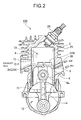
- FIGS. 2 to 4 are longitudinal sectional views of the engine 100. Referring to FIGS. 2 to 4 , reference numeral 2 denotes a cylinder and reference numeral 4 denotes a cylinder bore ( FIG. 2 ).
- a piston 6 is inserted into the cylinder bore 4 and can move reciprocatably.
- the cylinder 2 includes, across the cylinder bore 4, a gas mixture port 8 located on one side of the cylinder bore 4 and an exhaust port 10 located on the other side. The gas mixture port 8 and the exhaust port 10 are opened and closed by the piston 6.
- FIGS. 2 and 3 are longitudinal sectional views of the engine 100 taken along line II(III)-II(III) in FIG. 1 .
- FIG. 2 shows a state in which the piston 6 is positioned at the bottom dead center (BDC).
- FIG. 3 shows a state in which the piston 6 is positioned at the top dead center.
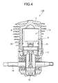
- FIG. 4 is a longitudinal sectional view of the engine 100 taken along line IV-IV in FIG. 1 .
- crankshaft 14 which is an engine output shaft, is disposed in a crank chamber 12.
- the crankshaft 14 is coupled to the piston 6 via a coupling rod 16.
- a reciprocating motion of the piston 6 is converted into a rotary motion by the crankshaft 14.
- the piston 6 inserted into the cylinder bore 4 defines a cylinder chamber 18.
- An ignition plug 20 is attached to the top of the cylinder 2 to face the cylinder chamber 18.
- the cylinder 2 includes two pairs of scavenging passages 22 located on the left and right when viewed in plan view.
- the scavenging passages 22 on the left and right are respectively located between the gas mixture port 8 and the exhaust port 10 when the cylinder chamber 18 is viewed in plan view.
- first and second pairs of scavenging ports 24A and 24B are joined with the respective scavenging passages 22.
- the pairs of scavenging ports 24A and 24B are positioned side by side ( FIGS. 1 and 2 ).
- An intake system of the engine 100 includes an air cleaner, a carburetor, a gas mixture passage, and a fresh air passage, although not shown in the figures.
- a gas mixture generated by the carburetor is fed to the gas mixture port 8 through the gas mixture passage.
- Fresh air filtered by the air cleaner is fed to the pair of left and right fresh air ports 26 through the fresh air passage as in the conventional engine.
- a pair of left and right air grooves 6a is formed on the circumferential surface of the piston 6 ( FIGS. 1 to 3 ).
- the air grooves 6a in the piston 6 makes or blocks communication between the fresh air ports 26 and the scavenging ports 24.
- the fresh air is fed to the scavenging passages 22 through the fresh air ports 26, the piston air grooves 6a, and the scavenging ports 24.
- the operation of the air-cooled two-stroke internal combustion engine 100 is the same as the operation in the conventional engine.
- the exhaust port 10 opens and exhaust is started.
- the pressure in the crank chamber 12 rises according to the descent of the piston 6 and the scavenging ports 24 open following the exhaust port 10.
- gas in the scavenging passages 22 spouts from the scavenging ports 24 into the cylinder chamber 18 with the pressure in the crank chamber 12 and the scavenging process is executed.
- the gas mixture in the crank chamber 12 is supplied into the cylinder chamber 18 through the scavenging passage 22 and the scavenging port 24.
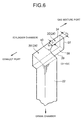
- FIGS. 5 and 6 are diagrams for explaining the shape of the scavenging port 24.
- FIG. 5 is a cross sectional view of the cylinder.
- a conventional example (a comparative example) is illustrated on the upper side and the embodiment is illustrated on the lower side.
- FIG. 6 is a diagram for explaining the shape of the scavenging port 24 with the scavenging passage 22 and the scavenging port 24 extracted.
- the scavenging port 24 is composed of a main port portion 28 directly ranging to the scavenging passage 22 and a port extension 30 extending from the main port portion 28 in the lateral direction, that is, the circumferential direction of the cylinder chamber 18.
- the port extension 30 extends to the opposite side of the exhaust port 10. In other words, the port extension 30 extends in the circumferential direction of the cylinder and to the side of the gas mixture port 8.
- the port extension 30 has a passage shape defined by four wall surfaces 32, 34, 36, and 38 of the cylinder 2 ( FIG. 6 ). Specifically, the port extension 30 extending to the side of the gas mixture port 8 configures a port extended passage defined by the end wall surface 32, the upper wall surface 34, the lower wall surface 36, and the rear wall surface 38 extending in the up and down direction.
- a corner portion (a boundary portion) 40 where the port extension 30 and the scavenging passage 22 are in contact with each other, is composed of an inclined surface that gradually approaches the cylinder chamber 18 toward the gas mixture port 8.
- the inclined surface may be, as another preferred form, a flat surface or may be, as still another preferred form, a smoothly curved surface as indicated by the example shown in the figures.
- depth D1 of a portion adjacent to the main port portion 28 is substantially equal to depth D2 of a portion on the side of the gas mixture port 8.
- the depth D2 of the portion on the side of the gas mixture port 8 may be small compared with the depth D1 of the portion adjacent to the main port portion 28.
- the port extension 30 may have a passage shape that gradually shallows toward the gas mixture port 8.
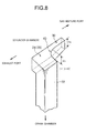
- FIG. 8 shows another modification.
- a height dimension H2 of the portion on the side of the gas mixture port 8 may be small compared with a height dimension H1 of the portion adjacent to the main port portion 28.
- the port extension 30 may have a shape tapered toward the gas mixture port 8.
- the depth dimension D is the same over the entire length of the port extension 30.
- a tapered shape may be adopted in the modification explained with reference to FIG. 7 (the shape that shallows toward the gas mixture port 8).
- the first and second scavenging ports 24A and 24B include first and second scavenging passages 22A and 22B communicating with the respective scavenging ports 24A and 24B.
- the first and second scavenging passages 22A and 22B may be composed of a common passage.
- the engine 100 in the embodiment is an engine of a reverse scavenging type.
- the engine 100 is designed such that a scavenging gas spouting from the first and second scavenging ports 24A and 24B basically flows to the opposite side of the exhaust port 10 (oriented in a direction of an arrow A in FIG. 5 ).
- At least a first sidewall 42 located on the side of the exhaust port 10 in the first scavenging passage 22A is composed of an inclined surface inclined toward the opposite side of the exhaust port 10.
- a second sidewall 44 opposed to the first sidewall 42, that is, a sidewall on the gas mixture port 8 side is also composed of an inclined surface inclined toward the opposite side of the exhaust port 10.
- the first sidewall 42 located on the side of the exhaust port 10 is composed of an inclined surface inclined toward the opposite side of the exhaust port 10.
- the second scavenging passage 22B has the same configuration.
- the second scavenging port 24B communicating with the second scavenging passage 22B has the same configuration as the first scavenging port 24A. Therefore, these sidewalls are denoted by reference numerals used for the sidewalls 42 and 44 of the first scavenging passage 22A and the first scavenging port 24A and explanation of the sidewalls is omitted.
- the end wall surface 32 of the port extension 30 is composed of an inclined surface inclined toward the gas mixture port 8 like the sidewalls 42 and 44 of the first and second scavenging passages 22A and 22B.
- an inclination angle of the end wall surface 32 of the port extension 30 may be set larger than that of the sidewalls 42 and 44 of the first and second scavenging passages 22A and 22B.
- the end wall surface 32 of the port extension 30 may be composed of an inclined surface greatly inclined toward the side of the gas mixture port 8.
- the scavenging port 24 of the engine 100 in the embodiment includes, as explained above, the main port portion 28 directly communicating with the scavenging passage 22 and the port extension 30 extending from the main port portion 28 in the lateral direction.
- the port extension 30 extends to the opposite side of the exhaust port 10, that is, the side of the gas mixture port 8.
- the fresh air is fed to the scavenging port 24 and the scavenging passage 22 through the groove 6a, that is, a piston air groove formed on the circumferential surface of the piston 6. Therefore, in a scavenging stroke, first, the fresh air accumulated in the scavenging passage 22 spouts to the cylinder chamber 18 as a scavenging gas. Initial scavenging process of the cylinder chamber 18 is performed by the leading fresh air. Subsequently, scavenging process is performed by the gas mixture in the crank chamber 12.
- the scavenging port 24 is composed of the main port portion 28 and the port extension 30.
- a flow of a main scavenging gas spouting from the main port portion 28 to the cylinder chamber 18 is directed to the opposite side of the exhaust port 10 as in the prior art. This state is indicated by the arrow A on the lower side of FIG. 5 .
- the main port portion 28 directly communicates with the scavenging passage 22.
- the port extension 30 is defined by the walls 32, 34, 36, and 38 ( FIG. 6 ). Consequently, the port extension 30 has a relatively small passage cross section. Therefore, a flow B of an incidental scavenging gas spouting to the cylinder chamber 18 through the port extension 30 is relatively high in speed compared with the main scavenging gas flow A spouting from the main port portion 28.
- the gas mixture in the crank chamber 12 flows into the cylinder chamber 18 through the scavenging passage 22 and the scavenging port 24.
- the main scavenging gas flow A is also attracted to the opposite side of the exhaust port 10 according to the Coanda effect by the incidental scavenging gas flow B. Consequently, it is possible to reduce the "blow-by loss" in which a part (the gas mixture) of the main scavenging gas flow A flows into the exhaust port 10.
- the scavenging port 24 includes the port extension 30 extending laterally from the main port portion 28, which directly communicates with the scavenging passage 22, the fresh air can be smoothly filled in the scavenging passage 22 from the piston air groove 6a through the scavenging port 24.
- the corner portion 40 (the boundary portion), where the port extension 30 and the scavenging passage 22 are in contact with each other, is composed of the inclined surface that gradually approaches the cylinder chamber 18 toward the gas mixture port 8. Consequently, the scavenging gas smoothly flows into the port extension 30 from the scavenging passage 22.
- a flowing direction of the scavenging gas flowing into the port extension 30 can be directed to the longitudinal direction of the port extension 30, which configures the port extended passage, that is, to the side of the gas mixture port 8.
- the corner portion 40 composed of the inclined surface is preferably composed of a curved surface. Consequently, the scavenging gas more smoothly flows into the port extension 30 from the scavenging passage 22.
- a flowing direction of the scavenging gas flowing into the port extension 30 from the scavenging passage 22 is directed to the longitudinal direction of the port extension 30, that is, to the side of the gas mixture port 8.
- the main scavenging gas flow A spouting from the main port portion 28 is deflected to a direction approaching the wall surface of the cylinder chamber 18 by the high-speed incidental scavenging gas flow B flowing to the direction approaching the wall surface of the cylinder chamber 18 ( FIG. 5 ). This means that an effect of further improving the effect of reducing the "blow-by loss" can be expected.
- an engine 200 of the conventional example (the comparative example) is drawn on the upper side of FIG. 5 .
- Components or elements same as that of the engine 100 in the embodiment are denoted by the same reference numerals and the conventional engine 200 will be explained.
- the first and second scavenging ports 24A and 24B respectively communicating with the first and second scavenging passages 22A and 22B in the conventional engine 200 correspond to the main port portion 28 of the engine 100 in the embodiment.
- the engine 100 in the embodiment had a fuel consumption reducing effect of about 4% and a reducing effect of HC in an exhaust gas of about 17%.
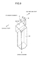
- FIG. 9 shows another embodiment concerning the shape of the scavenging port 24.
- FIG. 9 is a diagram corresponding to FIG. 6 .
- the scavenging port 24 is composed of the main port portion 28 ranging to the scavenging passage 22.
- the corner portion 40 is formed in a boundary portion between a portion of the scavenging port 24 on the opposite side of the exhaust port 10 and a wall surface of the scavenging passage 22 on the opposite side of the exhaust port 10 ranging to the portion.
- the scavenging port 24 has a shape gradually expanding to the side of the gas mixture port 8 toward the cylinder chamber 18.
- the inclined corner portion 40 is formed in the boundary portion between the wall surface of the scavenging passage 22 on the side of the gas mixture port 8 and the wall surface of the scavenging port 24.
- the corner portion 40 is preferably composed of a curved surface having a convex shape to the cylinder chamber 18 as shown in the figure.
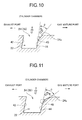
- FIG. 10 is a plan view for explaining the corner portion 40 (the boundary portion) composed of the inclined surface.
- FIG. 11 is a plan view of an example in which the inclined surface of the corner portion 40 is composed of a curved surface.
- the corner portion 40 is inclined in a direction away from the exhaust port 10 with respect to an extending direction toward the cylinder chamber 18 of the wall surface 44 located on the opposite side of the exhaust port 10 of the scavenging passage 22.
- the corner portion 40 is further inclined than the inclination of the wall surface 44 in a deep portion of the scavenging passage 22, that is, a portion far from the cylinder chamber 18.
- An angle of the further inclination of the corner portion 40 is indicated by " ⁇ ".
- the extending direction toward the cylinder chamber 18 of the wall surface 44 located on the opposite side of the exhaust port 10 of the scavenging passage 22 substantially defines a basic spouting direction of the scavenging gas flow defined by the scavenging passage 22 and the scavenging port 24.
- the spouting direction of the scavenging gas flow is equivalent to the orientation direction of the main scavenging gas flow A in the embodiment explained with reference to FIGS. 1 to 9 .
- the rear wall surface 38 of the scavenging port 24 ranging to the corner portion 40 continues to the inclined surface of the corner portion 40. That is, the scavenging port 24 includes the rear wall surface 38 continuing to the corner portion 40 and extending in a direction away from the exhaust port 10. Therefore, the scavenging port 24 continuing to the corner portion 40 composed of the inclined surface in the boundary portion between the scavenging passage 22 and the scavenging port 24 has a shape expanding to the opposite side of the exhaust port 10.
- the rear wall surface 38 of the scavenging port 24 ranging to the corner portion 40 also continues to the curved inclined surface of the corner portion 40 and extends in the direction away from the exhaust port 10.
- the incidental scavenging gas flow B on the side close to the gas mixture port 8 (the opposite side of the exhaust port 10) in the scavenging gas spouting from the scavenging port 24 is relatively high in speed compared with the main scavenging gas flow A on the side close to the exhaust port 10. Therefore, the main scavenging gas flow A on the side close to the exhaust port 10 is deflected to the direction approaching the wall surface of the cylinder chamber 18 according to the Coanda effect based on the relatively high-speed incidental scavenging gas flow B incidental to the main scavenging gas flow A and on the side close to the gas mixture port 8. Consequently, it is possible to improve the reduction effect of the "blow-by loss".
- FIG. 12 shows an engine 120 in a modification of the first embodiment.
- the first scavenging port 24A located near the exhaust port 10 is composed of the main port portion 28 and the port extension 30.
- the second scavenging port 24B located near the gas mixture port 8 has a port shape that directly communicates with the second scavenging passage 22B as in the prior art.
- the engine 120 in this modification can has effects same as that of the engine 100 in the first embodiment. It goes without saying that the scavenging port 24 in the other embodiment shown in FIG. 9 and the conventional scavenging port may be combined.
- the engine 100 includes the two scavenging ports 24A and 24B on one side.
- the number of the scavenging ports 24 is not limited.
- the engine may include one scavenging port 24 on one side or three scavenging ports 24 on one side (see Patent Document No. 5).
- the scavenging ports 24 may be arranged symmetrically on the left and right or may be arranged asymmetrically.
- the present invention can also be effectively applied to an engine of a type for performing scavenging only with the gas mixture in the crank chamber 12 (an engine of a scavenging type that does not use the fresh air).
- an engine of a scavenging type that does not use the fresh air can also be applied to an engine of a type in which a reed valve 52 is interposed between a fresh air passage 50 of an intake system and the scavenging passage 22.
- the gas mixture port 8 and the exhaust port 10 are arranged in positions opposed to each other in a diameter direction across the cylinder chamber 18.
- the gas mixture port 8 and the exhaust port 10 are located on the same side.
- the present invention can also be effectively applied to this type of engine.
- the exhaust port 10 is arranged on one side of the cylinder chamber 18 and the fresh air port 26 is arranged on the other side of the cylinder chamber 18.
- the fresh air port 26 and the exhaust port 10 are arranged on the same side.
- the present invention can also be effectively applied to this type of engine.
- the present invention can be widely applied to the two-stroke internal combustion engine.
- the present invention can be effectively applied to working machines, in particular, portable or handheld working machines such as a brush cutter, a blower, and a chain saw.
Landscapes
- Engineering & Computer Science (AREA)
- Chemical & Material Sciences (AREA)
- Combustion & Propulsion (AREA)
- Mechanical Engineering (AREA)
- General Engineering & Computer Science (AREA)
- Cylinder Crankcases Of Internal Combustion Engines (AREA)
- Combustion Methods Of Internal-Combustion Engines (AREA)
Applications Claiming Priority (1)
| Application Number | Priority Date | Filing Date | Title |
|---|---|---|---|
| JP2013032886A JP6101106B2 (ja) | 2013-02-22 | 2013-02-22 | 2ストローク内燃エンジン |
Publications (3)
| Publication Number | Publication Date |
|---|---|
| EP2770180A2 true EP2770180A2 (de) | 2014-08-27 |
| EP2770180A3 EP2770180A3 (de) | 2014-11-05 |
| EP2770180B1 EP2770180B1 (de) | 2017-08-02 |
Family
ID=50193217
Family Applications (1)
| Application Number | Title | Priority Date | Filing Date |
|---|---|---|---|
| EP14156066.4A Active EP2770180B1 (de) | 2013-02-22 | 2014-02-21 | Zweitaktverbrennungsmotor |
Country Status (3)
| Country | Link |
|---|---|
| US (1) | US8955475B2 (de) |
| EP (1) | EP2770180B1 (de) |
| JP (1) | JP6101106B2 (de) |
Cited By (2)
| Publication number | Priority date | Publication date | Assignee | Title |
|---|---|---|---|---|
| EP3184775A1 (de) * | 2015-12-21 | 2017-06-28 | Yamabiko Corporation | Luftgekühlter zweitakt-motor vom luftführungstyp |
| EP4198279A1 (de) * | 2021-12-16 | 2023-06-21 | Yamabiko Corporation | Zweitaktmotor mit schnuerlerspülung |
Families Citing this family (1)
| Publication number | Priority date | Publication date | Assignee | Title |
|---|---|---|---|---|
| JP7819289B2 (ja) * | 2022-02-25 | 2026-02-24 | 株式会社やまびこ | 空気吸気式2ストロークエンジン |
Citations (4)
| Publication number | Priority date | Publication date | Assignee | Title |
|---|---|---|---|---|
| JPS60222522A (ja) | 1984-04-20 | 1985-11-07 | Nippon Clean Engine Res | 2サイクル機関の掃気孔並びに掃気通路 |
| WO1998057053A1 (en) | 1997-06-11 | 1998-12-17 | Komatsu Zenoah Co. | Stratified scavenging two-cycle engine |
| JP2001173447A (ja) | 1999-12-15 | 2001-06-26 | Komatsu Zenoah Co | ピストンバルブ式層状掃気2サイクルエンジン |
| US7082910B2 (en) | 1999-01-19 | 2006-08-01 | Aktiebolaget Electrolux | Two-stroke internal combustion engine |
Family Cites Families (9)
| Publication number | Priority date | Publication date | Assignee | Title |
|---|---|---|---|---|
| US2724372A (en) * | 1952-08-05 | 1955-11-22 | Fairbanks Morse & Co | Engine cylinder scavenging |
| US3059626A (en) * | 1960-03-15 | 1962-10-23 | Nordberg Manufacturing Co | Two-cycle scavenging system |
| DE19618266C2 (de) * | 1996-05-07 | 1998-03-19 | Stihl Maschf Andreas | Zweitaktmotor mit Spülkanälen |
| JP3623330B2 (ja) * | 1996-12-16 | 2005-02-23 | 株式会社共立 | 2サイクルエンジンのシリンダ |
| US5769040A (en) * | 1997-04-18 | 1998-06-23 | Christner; Oval F. | Two cycle internal combustion engine |
| DE10019983B4 (de) * | 2000-04-22 | 2011-07-28 | Andreas Stihl AG & Co., 71336 | Druckgusszylinder für einen Zweitaktmotor |
| JP4878265B2 (ja) * | 2006-11-09 | 2012-02-15 | ハスクバーナ・ゼノア株式会社 | 2サイクルエンジン |
| JP2008274804A (ja) * | 2007-04-26 | 2008-11-13 | Ihi Shibaura Machinery Corp | 2サイクルエンジン |
| JP5780888B2 (ja) | 2010-12-13 | 2015-09-16 | 株式会社やまびこ | 2サイクルエンジン |
-
2013
- 2013-02-22 JP JP2013032886A patent/JP6101106B2/ja active Active
-
2014
- 2014-02-21 US US14/185,941 patent/US8955475B2/en active Active
- 2014-02-21 EP EP14156066.4A patent/EP2770180B1/de active Active
Patent Citations (5)
| Publication number | Priority date | Publication date | Assignee | Title |
|---|---|---|---|---|
| JPS60222522A (ja) | 1984-04-20 | 1985-11-07 | Nippon Clean Engine Res | 2サイクル機関の掃気孔並びに掃気通路 |
| WO1998057053A1 (en) | 1997-06-11 | 1998-12-17 | Komatsu Zenoah Co. | Stratified scavenging two-cycle engine |
| US7082910B2 (en) | 1999-01-19 | 2006-08-01 | Aktiebolaget Electrolux | Two-stroke internal combustion engine |
| US7565886B2 (en) | 1999-01-19 | 2009-07-28 | Husqvarna Ab | Two-stroke internal combustion engine |
| JP2001173447A (ja) | 1999-12-15 | 2001-06-26 | Komatsu Zenoah Co | ピストンバルブ式層状掃気2サイクルエンジン |
Cited By (4)
| Publication number | Priority date | Publication date | Assignee | Title |
|---|---|---|---|---|
| EP3184775A1 (de) * | 2015-12-21 | 2017-06-28 | Yamabiko Corporation | Luftgekühlter zweitakt-motor vom luftführungstyp |
| US10036304B2 (en) | 2015-12-21 | 2018-07-31 | Yamabiko Corporation | Leading-air type two-stroke air-cooled engine |
| EP4198279A1 (de) * | 2021-12-16 | 2023-06-21 | Yamabiko Corporation | Zweitaktmotor mit schnuerlerspülung |
| US11828221B2 (en) | 2021-12-16 | 2023-11-28 | Yamabiko Corporation | Schnuerle scavenging two-stroke engine |
Also Published As
| Publication number | Publication date |
|---|---|
| EP2770180B1 (de) | 2017-08-02 |
| US20140238371A1 (en) | 2014-08-28 |
| US8955475B2 (en) | 2015-02-17 |
| JP2014163244A (ja) | 2014-09-08 |
| JP6101106B2 (ja) | 2017-03-22 |
| EP2770180A3 (de) | 2014-11-05 |
Similar Documents
| Publication | Publication Date | Title |
|---|---|---|
| CN103912362B (zh) | 层状扫气二冲程发动机 | |
| EP3006693B1 (de) | Zweitaktverbrennungsmotor mit schichtspülung vom luftführungstyp | |
| US6640755B2 (en) | Two-cycle internal combustion engine | |
| EP2770180B1 (de) | Zweitaktverbrennungsmotor | |
| US10190534B2 (en) | Two-cycle engine | |
| US7255072B2 (en) | Two-stroke internal combustion engine | |
| JP4585920B2 (ja) | 2サイクル内燃エンジン | |
| JP4249638B2 (ja) | 2サイクルエンジン | |
| JP4606966B2 (ja) | 層状掃気2サイクル内燃エンジン | |
| US20100037874A1 (en) | Two-stroke engine emission control | |
| JP3773507B2 (ja) | 2サイクル内燃エンジン | |
| JP7105160B2 (ja) | 層状掃気エンジン及び携帯型作業機械 | |
| JP2010043560A (ja) | 2サイクルエンジン | |
| JP6425240B2 (ja) | 空気先導型層状掃気式2サイクル内燃エンジン | |
| WO2009093310A1 (ja) | 2サイクルエンジン | |
| JP2001329844A (ja) | 2サイクルエンジン | |
| EP4124733A1 (de) | Zweitaktmotor | |
| AU2010241402B1 (en) | Two-Stroke Engine Porting Arrangement | |
| JP6411159B2 (ja) | 空気先導型層状掃気式2サイクル内燃エンジン | |
| CN120667242A (zh) | 一种二冲程发动机扫气系统及二冲程发动机 | |
| JP5594026B2 (ja) | 2サイクルエンジンおよびそれを備えたエンジン作業機 | |
| US20070193548A1 (en) | Multi-port piston and internal combustion engine | |
| CZ20013583A3 (cs) | Spalovací motor |
Legal Events
| Date | Code | Title | Description |
|---|---|---|---|
| PUAI | Public reference made under article 153(3) epc to a published international application that has entered the european phase |
Free format text: ORIGINAL CODE: 0009012 |
|
| 17P | Request for examination filed |
Effective date: 20140221 |
|
| AK | Designated contracting states |
Kind code of ref document: A2 Designated state(s): AL AT BE BG CH CY CZ DE DK EE ES FI FR GB GR HR HU IE IS IT LI LT LU LV MC MK MT NL NO PL PT RO RS SE SI SK SM TR |
|
| AX | Request for extension of the european patent |
Extension state: BA ME |
|
| PUAL | Search report despatched |
Free format text: ORIGINAL CODE: 0009013 |
|
| AK | Designated contracting states |
Kind code of ref document: A3 Designated state(s): AL AT BE BG CH CY CZ DE DK EE ES FI FR GB GR HR HU IE IS IT LI LT LU LV MC MK MT NL NO PL PT RO RS SE SI SK SM TR |
|
| AX | Request for extension of the european patent |
Extension state: BA ME |
|
| RIC1 | Information provided on ipc code assigned before grant |
Ipc: F02B 25/16 20060101ALI20141002BHEP Ipc: F02B 25/02 20060101AFI20141002BHEP Ipc: F02B 33/04 20060101ALI20141002BHEP Ipc: F02B 75/02 20060101ALI20141002BHEP |
|
| R17P | Request for examination filed (corrected) |
Effective date: 20150505 |
|
| RBV | Designated contracting states (corrected) |
Designated state(s): AL AT BE BG CH CY CZ DE DK EE ES FI FR GB GR HR HU IE IS IT LI LT LU LV MC MK MT NL NO PL PT RO RS SE SI SK SM TR |
|
| 17Q | First examination report despatched |
Effective date: 20160128 |
|
| GRAP | Despatch of communication of intention to grant a patent |
Free format text: ORIGINAL CODE: EPIDOSNIGR1 |
|
| STAA | Information on the status of an ep patent application or granted ep patent |
Free format text: STATUS: GRANT OF PATENT IS INTENDED |
|
| INTG | Intention to grant announced |
Effective date: 20170210 |
|
| GRAS | Grant fee paid |
Free format text: ORIGINAL CODE: EPIDOSNIGR3 |
|
| GRAA | (expected) grant |
Free format text: ORIGINAL CODE: 0009210 |
|
| STAA | Information on the status of an ep patent application or granted ep patent |
Free format text: STATUS: THE PATENT HAS BEEN GRANTED |
|
| AK | Designated contracting states |
Kind code of ref document: B1 Designated state(s): AL AT BE BG CH CY CZ DE DK EE ES FI FR GB GR HR HU IE IS IT LI LT LU LV MC MK MT NL NO PL PT RO RS SE SI SK SM TR |
|
| REG | Reference to a national code |
Ref country code: CH Ref legal event code: EP Ref country code: AT Ref legal event code: REF Ref document number: 914751 Country of ref document: AT Kind code of ref document: T Effective date: 20170815 |
|
| REG | Reference to a national code |
Ref country code: IE Ref legal event code: FG4D |
|
| REG | Reference to a national code |
Ref country code: DE Ref legal event code: R096 Ref document number: 602014012401 Country of ref document: DE |
|
| REG | Reference to a national code |
Ref country code: SE Ref legal event code: TRGR |
|
| REG | Reference to a national code |
Ref country code: NL Ref legal event code: MP Effective date: 20170802 |
|
| REG | Reference to a national code |
Ref country code: AT Ref legal event code: MK05 Ref document number: 914751 Country of ref document: AT Kind code of ref document: T Effective date: 20170802 |
|
| REG | Reference to a national code |
Ref country code: LT Ref legal event code: MG4D |
|
| PG25 | Lapsed in a contracting state [announced via postgrant information from national office to epo] |
Ref country code: NO Free format text: LAPSE BECAUSE OF FAILURE TO SUBMIT A TRANSLATION OF THE DESCRIPTION OR TO PAY THE FEE WITHIN THE PRESCRIBED TIME-LIMIT Effective date: 20171102 Ref country code: NL Free format text: LAPSE BECAUSE OF FAILURE TO SUBMIT A TRANSLATION OF THE DESCRIPTION OR TO PAY THE FEE WITHIN THE PRESCRIBED TIME-LIMIT Effective date: 20170802 Ref country code: AT Free format text: LAPSE BECAUSE OF FAILURE TO SUBMIT A TRANSLATION OF THE DESCRIPTION OR TO PAY THE FEE WITHIN THE PRESCRIBED TIME-LIMIT Effective date: 20170802 Ref country code: LT Free format text: LAPSE BECAUSE OF FAILURE TO SUBMIT A TRANSLATION OF THE DESCRIPTION OR TO PAY THE FEE WITHIN THE PRESCRIBED TIME-LIMIT Effective date: 20170802 Ref country code: HR Free format text: LAPSE BECAUSE OF FAILURE TO SUBMIT A TRANSLATION OF THE DESCRIPTION OR TO PAY THE FEE WITHIN THE PRESCRIBED TIME-LIMIT Effective date: 20170802 Ref country code: FI Free format text: LAPSE BECAUSE OF FAILURE TO SUBMIT A TRANSLATION OF THE DESCRIPTION OR TO PAY THE FEE WITHIN THE PRESCRIBED TIME-LIMIT Effective date: 20170802 |
|
| REG | Reference to a national code |
Ref country code: FR Ref legal event code: PLFP Year of fee payment: 5 |
|
| PG25 | Lapsed in a contracting state [announced via postgrant information from national office to epo] |
Ref country code: BG Free format text: LAPSE BECAUSE OF FAILURE TO SUBMIT A TRANSLATION OF THE DESCRIPTION OR TO PAY THE FEE WITHIN THE PRESCRIBED TIME-LIMIT Effective date: 20171102 Ref country code: RS Free format text: LAPSE BECAUSE OF FAILURE TO SUBMIT A TRANSLATION OF THE DESCRIPTION OR TO PAY THE FEE WITHIN THE PRESCRIBED TIME-LIMIT Effective date: 20170802 Ref country code: PL Free format text: LAPSE BECAUSE OF FAILURE TO SUBMIT A TRANSLATION OF THE DESCRIPTION OR TO PAY THE FEE WITHIN THE PRESCRIBED TIME-LIMIT Effective date: 20170802 Ref country code: IS Free format text: LAPSE BECAUSE OF FAILURE TO SUBMIT A TRANSLATION OF THE DESCRIPTION OR TO PAY THE FEE WITHIN THE PRESCRIBED TIME-LIMIT Effective date: 20171202 Ref country code: LV Free format text: LAPSE BECAUSE OF FAILURE TO SUBMIT A TRANSLATION OF THE DESCRIPTION OR TO PAY THE FEE WITHIN THE PRESCRIBED TIME-LIMIT Effective date: 20170802 Ref country code: GR Free format text: LAPSE BECAUSE OF FAILURE TO SUBMIT A TRANSLATION OF THE DESCRIPTION OR TO PAY THE FEE WITHIN THE PRESCRIBED TIME-LIMIT Effective date: 20171103 Ref country code: ES Free format text: LAPSE BECAUSE OF FAILURE TO SUBMIT A TRANSLATION OF THE DESCRIPTION OR TO PAY THE FEE WITHIN THE PRESCRIBED TIME-LIMIT Effective date: 20170802 |
|
| PG25 | Lapsed in a contracting state [announced via postgrant information from national office to epo] |
Ref country code: CZ Free format text: LAPSE BECAUSE OF FAILURE TO SUBMIT A TRANSLATION OF THE DESCRIPTION OR TO PAY THE FEE WITHIN THE PRESCRIBED TIME-LIMIT Effective date: 20170802 Ref country code: RO Free format text: LAPSE BECAUSE OF FAILURE TO SUBMIT A TRANSLATION OF THE DESCRIPTION OR TO PAY THE FEE WITHIN THE PRESCRIBED TIME-LIMIT Effective date: 20170802 Ref country code: DK Free format text: LAPSE BECAUSE OF FAILURE TO SUBMIT A TRANSLATION OF THE DESCRIPTION OR TO PAY THE FEE WITHIN THE PRESCRIBED TIME-LIMIT Effective date: 20170802 |
|
| REG | Reference to a national code |
Ref country code: DE Ref legal event code: R097 Ref document number: 602014012401 Country of ref document: DE |
|
| PG25 | Lapsed in a contracting state [announced via postgrant information from national office to epo] |
Ref country code: IT Free format text: LAPSE BECAUSE OF FAILURE TO SUBMIT A TRANSLATION OF THE DESCRIPTION OR TO PAY THE FEE WITHIN THE PRESCRIBED TIME-LIMIT Effective date: 20170802 Ref country code: EE Free format text: LAPSE BECAUSE OF FAILURE TO SUBMIT A TRANSLATION OF THE DESCRIPTION OR TO PAY THE FEE WITHIN THE PRESCRIBED TIME-LIMIT Effective date: 20170802 Ref country code: SK Free format text: LAPSE BECAUSE OF FAILURE TO SUBMIT A TRANSLATION OF THE DESCRIPTION OR TO PAY THE FEE WITHIN THE PRESCRIBED TIME-LIMIT Effective date: 20170802 Ref country code: SM Free format text: LAPSE BECAUSE OF FAILURE TO SUBMIT A TRANSLATION OF THE DESCRIPTION OR TO PAY THE FEE WITHIN THE PRESCRIBED TIME-LIMIT Effective date: 20170802 |
|
| PLBE | No opposition filed within time limit |
Free format text: ORIGINAL CODE: 0009261 |
|
| STAA | Information on the status of an ep patent application or granted ep patent |
Free format text: STATUS: NO OPPOSITION FILED WITHIN TIME LIMIT |
|
| 26N | No opposition filed |
Effective date: 20180503 |
|
| PG25 | Lapsed in a contracting state [announced via postgrant information from national office to epo] |
Ref country code: SI Free format text: LAPSE BECAUSE OF FAILURE TO SUBMIT A TRANSLATION OF THE DESCRIPTION OR TO PAY THE FEE WITHIN THE PRESCRIBED TIME-LIMIT Effective date: 20170802 |
|
| REG | Reference to a national code |
Ref country code: CH Ref legal event code: PL |
|
| PG25 | Lapsed in a contracting state [announced via postgrant information from national office to epo] |
Ref country code: MC Free format text: LAPSE BECAUSE OF FAILURE TO SUBMIT A TRANSLATION OF THE DESCRIPTION OR TO PAY THE FEE WITHIN THE PRESCRIBED TIME-LIMIT Effective date: 20170802 |
|
| GBPC | Gb: european patent ceased through non-payment of renewal fee |
Effective date: 20180221 |
|
| REG | Reference to a national code |
Ref country code: IE Ref legal event code: MM4A |
|
| REG | Reference to a national code |
Ref country code: BE Ref legal event code: MM Effective date: 20180228 |
|
| PG25 | Lapsed in a contracting state [announced via postgrant information from national office to epo] |
Ref country code: LI Free format text: LAPSE BECAUSE OF NON-PAYMENT OF DUE FEES Effective date: 20180228 Ref country code: CH Free format text: LAPSE BECAUSE OF NON-PAYMENT OF DUE FEES Effective date: 20180228 Ref country code: LU Free format text: LAPSE BECAUSE OF NON-PAYMENT OF DUE FEES Effective date: 20180221 |
|
| PG25 | Lapsed in a contracting state [announced via postgrant information from national office to epo] |
Ref country code: IE Free format text: LAPSE BECAUSE OF NON-PAYMENT OF DUE FEES Effective date: 20180221 |
|
| PG25 | Lapsed in a contracting state [announced via postgrant information from national office to epo] |
Ref country code: BE Free format text: LAPSE BECAUSE OF NON-PAYMENT OF DUE FEES Effective date: 20180228 Ref country code: GB Free format text: LAPSE BECAUSE OF NON-PAYMENT OF DUE FEES Effective date: 20180221 |
|
| PG25 | Lapsed in a contracting state [announced via postgrant information from national office to epo] |
Ref country code: MT Free format text: LAPSE BECAUSE OF NON-PAYMENT OF DUE FEES Effective date: 20180221 |
|
| PG25 | Lapsed in a contracting state [announced via postgrant information from national office to epo] |
Ref country code: TR Free format text: LAPSE BECAUSE OF FAILURE TO SUBMIT A TRANSLATION OF THE DESCRIPTION OR TO PAY THE FEE WITHIN THE PRESCRIBED TIME-LIMIT Effective date: 20170802 |
|
| PG25 | Lapsed in a contracting state [announced via postgrant information from national office to epo] |
Ref country code: PT Free format text: LAPSE BECAUSE OF FAILURE TO SUBMIT A TRANSLATION OF THE DESCRIPTION OR TO PAY THE FEE WITHIN THE PRESCRIBED TIME-LIMIT Effective date: 20170802 Ref country code: HU Free format text: LAPSE BECAUSE OF FAILURE TO SUBMIT A TRANSLATION OF THE DESCRIPTION OR TO PAY THE FEE WITHIN THE PRESCRIBED TIME-LIMIT; INVALID AB INITIO Effective date: 20140221 |
|
| PG25 | Lapsed in a contracting state [announced via postgrant information from national office to epo] |
Ref country code: CY Free format text: LAPSE BECAUSE OF FAILURE TO SUBMIT A TRANSLATION OF THE DESCRIPTION OR TO PAY THE FEE WITHIN THE PRESCRIBED TIME-LIMIT Effective date: 20170802 Ref country code: MK Free format text: LAPSE BECAUSE OF NON-PAYMENT OF DUE FEES Effective date: 20170802 |
|
| PG25 | Lapsed in a contracting state [announced via postgrant information from national office to epo] |
Ref country code: AL Free format text: LAPSE BECAUSE OF FAILURE TO SUBMIT A TRANSLATION OF THE DESCRIPTION OR TO PAY THE FEE WITHIN THE PRESCRIBED TIME-LIMIT Effective date: 20170802 |
|
| PGFP | Annual fee paid to national office [announced via postgrant information from national office to epo] |
Ref country code: SE Payment date: 20260218 Year of fee payment: 13 |
|
| PGFP | Annual fee paid to national office [announced via postgrant information from national office to epo] |
Ref country code: DE Payment date: 20260218 Year of fee payment: 13 |
|
| PGFP | Annual fee paid to national office [announced via postgrant information from national office to epo] |
Ref country code: FR Payment date: 20260218 Year of fee payment: 13 |