EP2770860B1 - Strombetriebenes aerosolerzeugungssystem mit aerosolherstellungssteuerung - Google Patents
Strombetriebenes aerosolerzeugungssystem mit aerosolherstellungssteuerung Download PDFInfo
- Publication number
- EP2770860B1 EP2770860B1 EP12808691.5A EP12808691A EP2770860B1 EP 2770860 B1 EP2770860 B1 EP 2770860B1 EP 12808691 A EP12808691 A EP 12808691A EP 2770860 B1 EP2770860 B1 EP 2770860B1
- Authority
- EP
- European Patent Office
- Prior art keywords
- aerosol
- parameter
- flow rate
- aerosol generating
- generating element
- Prior art date
- Legal status (The legal status is an assumption and is not a legal conclusion. Google has not performed a legal analysis and makes no representation as to the accuracy of the status listed.)
- Active
Links
Images
Classifications
-
- A—HUMAN NECESSITIES
- A24—TOBACCO; CIGARS; CIGARETTES; SIMULATED SMOKING DEVICES; SMOKERS' REQUISITES
- A24F—SMOKERS' REQUISITES; MATCH BOXES; SIMULATED SMOKING DEVICES
- A24F40/00—Electrically operated smoking devices; Component parts thereof; Manufacture thereof; Maintenance or testing thereof; Charging means specially adapted therefor
- A24F40/40—Constructional details, e.g. connection of cartridges and battery parts
- A24F40/46—Shape or structure of electric heating means
-
- F—MECHANICAL ENGINEERING; LIGHTING; HEATING; WEAPONS; BLASTING
- F24—HEATING; RANGES; VENTILATING
- F24H—FLUID HEATERS, e.g. WATER OR AIR HEATERS, HAVING HEAT-GENERATING MEANS, e.g. HEAT PUMPS, IN GENERAL
- F24H1/00—Water heaters, e.g. boilers, continuous-flow heaters or water-storage heaters
- F24H1/0018—Water heaters, e.g. boilers, continuous-flow heaters or water-storage heaters using electric energy supply
-
- A—HUMAN NECESSITIES
- A24—TOBACCO; CIGARS; CIGARETTES; SIMULATED SMOKING DEVICES; SMOKERS' REQUISITES
- A24F—SMOKERS' REQUISITES; MATCH BOXES; SIMULATED SMOKING DEVICES
- A24F40/00—Electrically operated smoking devices; Component parts thereof; Manufacture thereof; Maintenance or testing thereof; Charging means specially adapted therefor
- A24F40/50—Control or monitoring
- A24F40/51—Arrangement of sensors
-
- A—HUMAN NECESSITIES
- A61—MEDICAL OR VETERINARY SCIENCE; HYGIENE
- A61M—DEVICES FOR INTRODUCING MEDIA INTO, OR ONTO, THE BODY; DEVICES FOR TRANSDUCING BODY MEDIA OR FOR TAKING MEDIA FROM THE BODY; DEVICES FOR PRODUCING OR ENDING SLEEP OR STUPOR
- A61M11/00—Sprayers or atomisers specially adapted for therapeutic purposes
- A61M11/04—Sprayers or atomisers specially adapted for therapeutic purposes operated by the vapour pressure of the liquid to be sprayed or atomised
- A61M11/041—Sprayers or atomisers specially adapted for therapeutic purposes operated by the vapour pressure of the liquid to be sprayed or atomised using heaters
- A61M11/042—Sprayers or atomisers specially adapted for therapeutic purposes operated by the vapour pressure of the liquid to be sprayed or atomised using heaters electrical
-
- A—HUMAN NECESSITIES
- A61—MEDICAL OR VETERINARY SCIENCE; HYGIENE
- A61M—DEVICES FOR INTRODUCING MEDIA INTO, OR ONTO, THE BODY; DEVICES FOR TRANSDUCING BODY MEDIA OR FOR TAKING MEDIA FROM THE BODY; DEVICES FOR PRODUCING OR ENDING SLEEP OR STUPOR
- A61M15/00—Inhalators
- A61M15/06—Inhaling appliances shaped like cigars, cigarettes or pipes
-
- A—HUMAN NECESSITIES
- A24—TOBACCO; CIGARS; CIGARETTES; SIMULATED SMOKING DEVICES; SMOKERS' REQUISITES
- A24F—SMOKERS' REQUISITES; MATCH BOXES; SIMULATED SMOKING DEVICES
- A24F40/00—Electrically operated smoking devices; Component parts thereof; Manufacture thereof; Maintenance or testing thereof; Charging means specially adapted therefor
- A24F40/10—Devices using liquid inhalable precursors
-
- A—HUMAN NECESSITIES
- A61—MEDICAL OR VETERINARY SCIENCE; HYGIENE
- A61M—DEVICES FOR INTRODUCING MEDIA INTO, OR ONTO, THE BODY; DEVICES FOR TRANSDUCING BODY MEDIA OR FOR TAKING MEDIA FROM THE BODY; DEVICES FOR PRODUCING OR ENDING SLEEP OR STUPOR
- A61M16/00—Devices for influencing the respiratory system of patients by gas treatment, e.g. ventilators; Tracheal tubes
- A61M16/0003—Accessories therefor, e.g. sensors, vibrators, negative pressure
- A61M2016/0015—Accessories therefor, e.g. sensors, vibrators, negative pressure inhalation detectors
- A61M2016/0018—Accessories therefor, e.g. sensors, vibrators, negative pressure inhalation detectors electrical
- A61M2016/0024—Accessories therefor, e.g. sensors, vibrators, negative pressure inhalation detectors electrical with an on-off output signal, e.g. from a switch
-
- A—HUMAN NECESSITIES
- A61—MEDICAL OR VETERINARY SCIENCE; HYGIENE
- A61M—DEVICES FOR INTRODUCING MEDIA INTO, OR ONTO, THE BODY; DEVICES FOR TRANSDUCING BODY MEDIA OR FOR TAKING MEDIA FROM THE BODY; DEVICES FOR PRODUCING OR ENDING SLEEP OR STUPOR
- A61M2205/00—General characteristics of the apparatus
- A61M2205/02—General characteristics of the apparatus characterised by a particular materials
- A61M2205/0211—Ceramics
-
- A—HUMAN NECESSITIES
- A61—MEDICAL OR VETERINARY SCIENCE; HYGIENE
- A61M—DEVICES FOR INTRODUCING MEDIA INTO, OR ONTO, THE BODY; DEVICES FOR TRANSDUCING BODY MEDIA OR FOR TAKING MEDIA FROM THE BODY; DEVICES FOR PRODUCING OR ENDING SLEEP OR STUPOR
- A61M2205/00—General characteristics of the apparatus
- A61M2205/36—General characteristics of the apparatus related to heating or cooling
- A61M2205/3653—General characteristics of the apparatus related to heating or cooling by Joule effect, i.e. electric resistance
-
- A—HUMAN NECESSITIES
- A61—MEDICAL OR VETERINARY SCIENCE; HYGIENE
- A61M—DEVICES FOR INTRODUCING MEDIA INTO, OR ONTO, THE BODY; DEVICES FOR TRANSDUCING BODY MEDIA OR FOR TAKING MEDIA FROM THE BODY; DEVICES FOR PRODUCING OR ENDING SLEEP OR STUPOR
- A61M2205/00—General characteristics of the apparatus
- A61M2205/82—Internal energy supply devices
- A61M2205/8206—Internal energy supply devices battery-operated
Definitions
- the present invention relates to a method for controlling aerosol production.
- the present invention further relates to an aerosol generating system and more specifically to an electrically operated aerosol generation system.
- the present invention finds particular application as a method for controlling aerosol production in an aerosol generation system through at least one electric element of an electrically operated smoking system.
- WO-A-2009/132793 discloses an electrically heated smoking system.
- a liquid is stored in a liquid storage portion, and a capillary wick has a first end which extends into the liquid storage portion for contact with the liquid therein, and a second end which extends out of the liquid storage portion.
- a heating element heats the second end of the capillary wick.
- the heating element is in the form of a spirally wound electric heating element in electrical connection with a power supply, and surrounding the second end of the capillary wick. In use, the heating element may be activated by the user to switch on the power supply. Suction on a mouthpiece by the user causes air to be drawn into the electrically heated smoking system over the capillary wick and heating element and subsequently into the mouth of the user.
- WO2011/033396 discloses an electrically heated smoking system in which an air flow sensor is used to detect the direction and rate of air flow through the system.
- the system is configured to operate to generate smoke when the air flow direction corresponds to inhaling and reaches a predetermined threshold.
- aerosol condensation chamber One particular problem with an aerosol generating devices is condensation of the aerosol inside the device.
- the aerosol can condense into a liquid within the aerosol condensation chamber and the liquid can then leak out of the device.
- the liquid in the aerosol condensation chamber could leak while the device is not in use or while the device is in use, entering a user's mouth. Any liquid which enters the user's mouth could be unpleasant and potentially hazardous.
- a further problem with condensation within aerosol generating devices is that the condensates of the aerosol can migrate or settle onto the aerosol generating element and interfere with its operation. In the case of thermal vaporization, if an aerosol condensate is subsequently re-evaporated this can lead to chemical degradation of the original liquid formulation. This could result in an unpleasant taste or hazardous chemicals.
- a method of controlling aerosol production in an aerosol-generating device comprising:
- the device is configured to allow the air flow to be generated by a user inhalation.
- the step of determining comprises determining a value of the first parameter during an inhalation period.
- the step of changing the power supply comprises reducing the supply of power to zero.
- An aerosol is a suspension of solid particles or liquid droplets in a gas, such as air.
- a gas such as air.
- the rate of aerosol generation can be controlled.
- the remaining portion of the air flow can be used to remove or purge already generated aerosol, and thus reduce condensation within the device.
- the most desirable time to stop aerosol generation depends on the rate and variance of the air flow during a defined period. For a device driven by user inhalation, different users have different inhalation behaviour, and a single user can have different inhalation behaviour at different times.
- a set flow rate threshold for controlling aerosol production does not work equally well in removing produced aerosol for short sharp user inhalations and long slow inhalations.
- a flow threshold appropriate for a short sharp inhalation may never be reached by a user taking long slow inhalations.
- the present invention provides a method of controlling aerosol production, and in particular reducing or suspending aerosol production, based on a detected flow rate and on another measure called the first parameter which is indicative of the evolution of the flow characteristics of the air flow.
- the first parameter which is indicative of the evolution of the flow characteristics of the air flow.
- it does not have to be only the detected flow rate, but could be based on different puff parameters.
- the second parameter may be a parameter that does not have units of flow rate but is nevertheless a measure of flow rate.
- the flow sensor may operate by determining the resistance of an electrical filament in the air flow, and so the second parameter may be a resistance value rather than a flow rate calculated from a resistance value.
- the second parameter may be a parameter having a constant relationship with flow rate rather than the actual flow rate. The invention does not require an actual flow rate to be calculated.
- the third parameter is temperature or maximum flow rate, then advantageously the first parameter is proportional to a ratio between the second and third parameters.
- the first parameter is advantageously proportional to a product of the second and third parameters.
- the first parameter may simply be proportional to a rate of change of flow rate.
- first parameter depends on the design of the aerosol-generating device. Different designs may have different flow characteristics past a flow sensor, and different types of aerosol-generating devices may behave differently. Although the preferred examples are simple products or ratios of two detected or derived parameters, more complex combinations may be used.
- the aerosol generating element may be a mechanical device, such as a vibrating orifice transducer or a piezoelectric device. However, preferably, the aerosol generating element is an electrical heater comprising at least one heater element. The at least one electric heating element may be arranged to heat an aerosol-forming substrate to form the aerosol.
- the temperature of the heating element is a parameter that is indicative of the flow characteristics within the device. This may be used as the third parameter. For lower temperatures there is a high flow rate as the air flow provides a cooling effect. So, the temperature of the heating element will increase as the flow rate drops at the end of a user inhalation.
- the resistance of the heating element may be dependent on the temperature of the heating element, so that the resistance of the heating element may be used as the third parameter.
- the power supplied to the heater element to maintain a constant temperature is indicative of the flow rate and so may be used as the third parameter.
- the constant temperature may be a predetermined value or may be dynamically calculated based on one or more other measured parameters, such as flow rate.
- an electrically operated aerosol generating device comprising: at least one electric aerosol generating element for forming an aerosol from a substrate; a power supply for supplying power to the at least one aerosol generating element; and electric circuitry for controlling supply of power from the power supply to the at least one aerosol generating element, the electric circuitry including a sensor for detecting a air flow past the aerosol generating element and wherein the electric circuitry is arranged to:
- the device is configured to allow the air flow to be generated by a user inhalation.
- the device is configured to determine a value of the first parameter during an inhalation period.
- the third parameter is temperature or maximum flow rate, then preferably the first parameter is proportional to a ratio between the second and third parameters.
- the first parameter is preferably proportional to a product of the second and third parameters.
- the first parameter may simply be proportional to a rate of change of flow rate.
- the device may be configured to receive an aerosol-forming substrate.
- the aerosol generating element may be a mechanical device, such as a vibrating orifice transducer. However, preferably, the aerosol generating element is an electrical heater comprising at least one heater element. The at least one electric heating element may be arranged to heat an aerosol-forming substrate to form the aerosol.
- the temperature of the heating element is a parameter that is indicative of the flow characteristics within the device. Temperature may then be used as the third parameter. For lower temperatures there is a high flow rate as the air flow provides a cooling effect. So, the temperature of the heating element will increase as the flow rate drops at the end of a user inhalation (or other air flow period).
- the electrical resistance of the heating element may be dependent on the temperature of the heating element, so that the electrical resistance of the heating element may be used as the third parameter.
- the power supplied to the heater element to maintain a constant temperature is indicative of the flow rate and so may be used as the third parameter.
- the constant temperature may be a predetermined value or may be dynamically calculated based on one or more other measured parameters, such as flow rate.
- the electric circuitry is arranged to perform the method steps of the previous aspect of the invention.
- the electric circuitry may be hardwired. More preferably, however, the electric circuitry is programmable to perform the method steps of the previous aspect of the invention.
- the sensor may be any sensor which can detect airflow.
- the sensor may be an electro-mechanical device.
- the sensor may be any of: a mechanical device, an optical device, an opto-mechanical device, a micro electro mechanical systems (MEMS) based sensor and an acoustic sensor.
- MEMS micro electro mechanical systems
- the sensor can be a thermal conductive flow sensor, a pressure sensor, an anemometer and should be able to not only detect an airflow but should be able to measure the airflow. So, the sensor should be able to deliver an analogue electrical signal or digital information that is representative of the amplitude of the air flow.
- the electric heater may comprise a single heating element.
- the electric heater may comprise more than one heating element, for example two, or three, or four, or five, or six or more heating elements.
- the heating element or heating elements may be arranged appropriately so as to most effectively heat the aerosol-forming substrate.
- the at least one electric heating element preferably comprises an electrically resistive material.
- Suitable electrically resistive materials include but are not limited to: semiconductors such as doped ceramics, electrically "conductive" ceramics (such as, for example, molybdenum disilicide), carbon, graphite, metals, metal alloys and composite materials made of a ceramic material and a metallic material. Such composite materials may comprise doped or undoped ceramics. Examples of suitable doped ceramics include doped silicon carbides. Examples of suitable metals include titanium, zirconium, tantalum and metals from the platinum group.
- suitable metal alloys include stainless steel, Constantan, nickel-, cobalt-, chromium-, aluminium- titanium- zirconium-, hafnium-, niobium-, molybdenum-, tantalum-, tungsten-, tin-, gallium-, manganese- and iron-containing alloys, and super-alloys based on nickel, iron, cobalt, stainless steel, Timetal®, iron-aluminium based alloys and iron-manganese-aluminium based alloys. Timetal® is a registered trade mark of Titanium Metals Corporation, 1999 Broadway Suite 4300, Denver Colorado.
- the electrically resistive material may optionally be embedded in, encapsulated or coated with an insulating material or vice-versa, depending on the kinetics of energy transfer and the external physicochemical properties required.
- the heating element may comprise a metallic etched foil insulated between two layers of an inert material.
- the inert material may comprise Kapton®, all-polyimide or mica foil. Kapton® is a registered trade mark of E.I. du Pont de Nemours and Company, 1007 Market Street, Wilmington, Delaware 19898, United States of America.
- the at least one electric heating element may comprise an infra-red heating element, a photonic source, or an inductive heating element.
- the at least one electric heating element may take any suitable form.
- the at least one electric heating element may take the form of a heating blade.
- the at least one electric heating element may take the form of a casing or substrate having different electro-conductive portions, or an electrically resistive metallic tube.
- the aerosol-forming substrate is a liquid provided within a container, the container may incorporate a disposable heating element.
- one or more heating needles or rods that run through the centre of the aerosol-forming substrate may also be suitable.
- the at least one electric heating element may be a disk (end) heater or a combination of a disk heater with heating needles or rods.
- the at least one electric heating element may comprise a flexible sheet of material arranged to surround or partially surround the aerosol-forming substrate.
- Other alternatives include a heating wire or filament, for example a Ni-Cr, platinum, tungsten or alloy wire, or a heating plate.
- the heating element may be deposited in or on a rigid carrier material.
- the at least one electric heating element may comprise a heat sink, or heat reservoir comprising a material capable of absorbing and storing heat and subsequently releasing the heat over time to the aerosol-forming substrate.
- the heat sink may be formed of any suitable material, such as a suitable metal or ceramic material.
- the material has a high heat capacity (sensible heat storage material), or is a material capable of absorbing and subsequently releasing heat via a reversible process, such as a high temperature phase change.
- Suitable sensible heat storage materials include silica gel, alumina, carbon, glass mat, glass fibre, minerals, a metal or alloy such as aluminium, silver or lead, and a cellulose material such as paper.
- Other suitable materials which release heat via a reversible phase change include paraffin, sodium acetate, naphthalene, wax, polyethylene oxide, a metal, metal salt, a mixture of eutectic salts or an alloy.
- the heat sink or heat reservoir may be arranged such that it is directly in contact with the aerosol-forming substrate and can transfer the stored heat directly to the substrate.
- the heat stored in the heat sink or heat reservoir may be transferred to the aerosol-forming substrate by means of a heat conductor, such as a metallic tube.
- the at least one heating element may heat the aerosol-forming substrate by means of conduction.
- the heating element may be at least partially in contact with the substrate, or the carrier on which the substrate is deposited. Alternatively, the heat from the heating element may be conducted to heat conductive element.
- the at least one heating element may transfer heat to the incoming ambient air that is drawn through the electrically heated aerosol generating device during use, which in turn heats the aerosol-forming substrate by convection.
- the ambient air may be heated before passing through the aerosol-forming substrate.
- the aerosol-forming substrate is a liquid substrate, the ambient air may be first drawn through the substrate and then heated.
- the aerosol-forming substrate may be a solid aerosol-forming substrate.
- the aerosol-forming substrate preferably comprises a tobacco-containing material containing volatile tobacco flavour compounds which are released from the substrate upon heating.
- the aerosol-forming substrate may comprise a non-tobacco material.
- the aerosol-forming substrate may comprise tobacco-containing material and non-tobacco containing material.
- the aerosol-forming substrate further comprises an aerosol former. Examples of suitable aerosol formers are glycerine and propylene glycol.
- the aerosol-forming substrate may be a liquid aerosol-forming substrate.
- the electrically heated aerosol generating device further comprises a liquid storage portion.
- the liquid aerosol-forming substrate is stored in the liquid storage portion.
- the electrically heated aerosol generating device further comprises a capillary wick in communication with the liquid storage portion. It is also possible for a capillary wick for holding liquid to be provided without a liquid storage portion. In that embodiment, the capillary wick may be preloaded with liquid.
- the capillary wick is arranged to be in contact with liquid in the liquid storage portion.
- liquid is transferred from the liquid storage portion towards the at least one electric heating element by capillary action in the capillary wick.
- the capillary wick has a first end and a second end, the first end extending into the liquid storage portion for contact with liquid therein and the at least one electric heating element being arranged to heat liquid in the second end.
- the heating element is activated, the liquid at the second end of the capillary wick is vaporized by the heater to form the supersaturated vapour.
- the supersaturated vapour is mixed with and carried in the airflow.
- the heating element in combination with a capillary wick may provide a fast response, because that arrangement may provide a high surface area of liquid to the heating element. Control of the heating element according to the invention may therefore depend on the structure of the capillary wick arrangement.
- the liquid substrate may be absorbed into a porous carrier material, which may be made from any suitable absorbent plug or body, for example, a foamed metal or plastics material, polypropylene, terylene, nylon fibres or ceramic.
- the liquid substrate may be retained in the porous carrier material prior to use of the electrically heated aerosol generating device or alternatively, the liquid substrate material may be released into the porous carrier material during, or immediately prior to use.
- the liquid substrate may be provided in a capsule.
- the shell of the capsule preferably melts upon heating and releases the liquid substrate into the porous carrier material.
- the capsule may optionally contain a solid in combination with the liquid.
- the liquid has specific physical properties. These include, for example, a boiling point, vapour pressure, and surface tension characteristics to make them suitable for use in the aerosol generating device. Control of the at least one electric heating element may depend upon the physical properties of the liquid substrate.
- the liquid preferably comprises a tobacco-containing material comprising volatile tobacco flavour compounds which are released from the liquid upon heating. Alternatively, or in addition, the liquid may comprise a non-tobacco material.
- the liquid may include water, solvents, ethanol, plant extracts and natural or artificial flavours.
- the liquid further comprises an aerosol former. Examples of suitable aerosol formers are glycerine and propylene glycol.
- the liquid storage portion is preferably a container.
- the liquid storage portion may not be refillable. Thus, when the liquid in the liquid storage portion has been used up, the liquid storage portion, or the entire aerosol generating device, is replaced. Alternatively, the liquid storage portion may be refillable. In that case, the aerosol generating device may be replaced after a certain number of refills of the liquid storage portion.
- the liquid storage portion is arranged to hold liquid for a pre-determined number of puffs.
- the capillary wick may have a fibrous or spongy structure.
- the capillary wick preferably comprises a bundle of capillaries.
- the capillary wick may comprise a plurality of fibres or threads, or other fine bore tubes.
- the fibres or threads may be generally aligned in the longitudinal direction of the aerosol generating device.
- the capillary wick may comprise sponge-like or foam-like material formed into a rod shape.
- the rod shape may extend along the longitudinal direction of the aerosol generating device.
- the structure of the wick forms a plurality of small bores or tubes, through which the liquid can be transported to the electric heating element, by capillary action.
- the capillary wick may comprise any suitable material or combination of materials.
- the capillary wick may have any suitable capillarity and porosity so as to be used with different liquid physical properties such as density, viscosity, surface tension and vapour pressure.
- the capillary properties of the wick, combined with the properties of the liquid, ensure that the wick is always wet in the heating area.
- the aerosol-forming substrate may alternatively be any other sort of substrate, for example, a gas substrate, or any combination of the various types of substrate.
- the substrate may be completely contained within the electrically heated aerosol generating device. In that case, a user may puff on a mouthpiece of the electrically heated aerosol generating device.
- the substrate may be partially contained within the electrically heated aerosol generating device. In that case, the substrate may form part of a separate article and the user may puff directly on the separate article.
- the electrically heated aerosol generating device is an electrically heated smoking device.
- the electrically heated aerosol generating device may comprise an aerosol-forming chamber in which aerosol forms from a super saturated vapour, which aerosol is then carried into the mouth of the user.
- An air inlet, air outlet and the chamber are preferably arranged so as to define an airflow route from the air inlet to the air outlet via the aerosol-forming chamber, so as to convey the aerosol to the air outlet and into the mouth of a user. Condensation may form on the walls of the aerosol-forming chamber. The amount of condensation may depend on the amount of power supplied, particularly towards the end of the puff.
- the aerosol generating device comprises a housing.
- the housing is elongate.
- the structure of the housing, including the surface area available for condensation to form, will affect the aerosol properties and whether there is liquid leakage from the device.
- the housing may comprise a shell and a mouthpiece. In that case, all the components may be contained in either the shell or the mouthpiece.
- the housing may comprise any suitable material or combination of materials. Examples of suitable materials include metals, alloys, plastics or composite materials containing one or more of those materials, or thermoplastics that are suitable for food or pharmaceutical applications, for example polypropylene, polyetheretherketone (PEEK) and polyethylene.
- PEEK polyetheretherketone
- the material is light and non-brittle.
- the material of the housing may affect the amount of condensation forming on the housing which will, in turn, affect liquid leakage from the device
- the aerosol generating device is portable.
- the aerosol generating device may be a smoking device and may have a size comparable to a conventional cigar or cigarette.
- the smoking device may have a total length between approximately 30 mm and approximately 150 mm.
- the smoking device may have an external diameter between approximately 5 mm and approximately 30 mm.
- the method and electrically heated aerosol generating device provide the advantage that the amount of power supplied to the heating element may be tailored to the air flow profile, thereby providing an improved experience for the user and reducing the amount of aerosol that condenses within the housing of the device, without requiring any additional user or device actions.
- electric circuitry for an electrically operated aerosol generating device, the electric circuitry being arranged to perform the method of the other aspects of the invention.
- the electric circuitry is programmable to perform the method of the other aspects of the invention.
- the electric circuitry may be hardwired to perform the method of the other aspects of the invention.
- a computer program which, when run on programmable electric circuitry for an electrically operated aerosol generating device, causes the programmable electric circuitry to perform the method of the other aspects of the invention.
- a computer readable storage medium having stored thereon a computer program according to the previous aspect of the invention.
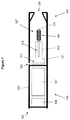
- Figure 1 shows one example of an electrically heated aerosol generating device.
- the device is a smoking device having a liquid storage portion.
- the smoking device 100 of Figure 1 comprises a housing 101 having a mouthpiece end 103 and a body end 105.
- an electric power supply in the form of battery 107 and electric circuitry in the form of hardware 109 and a puff detection device 111.
- a liquid storage portion in the form of cartridge 113 containing liquid 115, a capillary wick 117 and a heater 119 comprising at least one heating element. Note that the heater is only shown schematically in Figure 1 .
- the housing 101 also includes an air inlet 123, an air outlet 125 at the mouthpiece end and an aerosol-forming chamber 127.
- Liquid 115 is transferred or conveyed by capillary action from the cartridge 113 from the end of the wick 117 which extends into the cartridge to the other end of the wick 117 which is surrounded by the heater 119.
- the puff detection device 111 senses the puff and activates the heater 119.
- the battery 107 supplies energy to the heater 119 to heat the end of the wick 117 surrounded by the heater.
- the liquid in that end of the wick 117 is vaporized by the heater 119 to create a supersaturated vapour.
- the liquid being vaporized is replaced by further liquid moving along the wick 117 by capillary action. (This is sometimes referred to as "pumping action”.)
- the supersaturated vapour created is mixed with and carried in the airflow from the air inlet 123.
- the vapour condenses to form an inhalable aerosol, which is carried towards the outlet 125 and into the mouth of the user.
- the capillary wick can be made from a variety of porous or capillary materials and preferably has a known, pre-defined capillarity. Examples include ceramic- or graphite-based materials in the form of fibres or sintered powders. Wicks of different porosities can be used to accommodate different liquid physical properties such as density, viscosity, surface tension and vapour pressure.
- the wick must be suitable so that the required amount of liquid can be delivered to the heating element.
- the wick and heating element must be suitable so that the required amount of aerosol can be conveyed to the user.
- the hardware 109 and the puff detection device 111 are preferably programmable.
- the hardware 109 and puff detection device 111 can be used to manage the device operation. This assists with control of the particle size in the aerosol.
- FIG. 1 shows one example of an electrically heated aerosol generating device which may be used with the present invention.
- the electrically heated aerosol generating device simply needs to include or receive an aerosol forming substrate which can be heated by at least one electric heating element, powered by a power supply under the control of electric circuitry.
- the device need not be a smoking device.
- the aerosol forming substrate may be a solid substrate, rather than a liquid substrate.
- the aerosol forming substrate may be another form of substrate such as a gas substrate.
- the heating element may take any appropriate form.
- the overall shape and size of the housing could be altered and the housing could comprise a separable shell and mouthpiece. Other variations are, of course, possible.
- the electric circuitry comprising hardware 109 and the puff detection device 111, is programmable in order to control the supply of power to the heating element. This, in turn, affects the temperature profile which will affect the density of the aerosol produced.
- the term "temperature profile" refers to a graphic representation of the temperature of the heating element (or another similar measure, for example, the heat generated by the heating element) over the time taken for a puff.
- the hardware 109 and the puff detection device 111 may be hardwired to control the supply of power to the heating element. Again, this will affect the temperature profile which will affect the density of the aerosol generated.
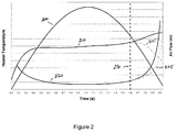
- FIG. 2 illustrates a method for controlling power to the heater of Figure 1 in accordance with a first embodiment of the invention.
- Curve 200 is the detected air flow through the device during a user inhalation period or puff.
- Curve 210 is the temperature of the heater during the same period. Power is applied to the heater when air flow through the device is first detected and is continuously applied at the same level until it is switched off. So the temperature of the heater initially rises until it reaches a fairly stable level, at which the cooling of the air flow balances the heating provided by the power supply.
- the heater temperature at is therefore sensitive to a change in air flow during a puff.
- Curve 220 is a plot of the temperature of the heater divided by the air flow. This curve is used to provide a normalised threshold for switching off power to the heater and will be referred to as the end of puff variable.
- Power to the heater is stopped when curve 220 reaches a threshold value (but only after the maximum flow rate has passed).
- the threshold value is preset and stored in the electric circuitry during manufacture. However, it is possible to have a threshold that is changed over time to be most appropriate for a particular user behavior.
- the power stop is shown by line 230, at 1.6 seconds into the puff. After power is stopped, the temperature of the heater goes down (dotted line 215). The corresponding end of puff variable curve is obtained for the decreasing temperature and is shown in dotted line 225.
- the threshold is selected so that the temperature of heater decreases enough to significantly reduce the generation of the aerosol up to the end of the puff, but not so early as to frustrate the device user.
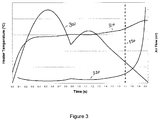
- Figure 3 shows another example in accordance with the first embodiment, with a more complex flow profile during a puff.
- Curve 300 shows the air flow
- curve 310 shows the heater temperature
- Power to the heater is stopped when the end of puff variable reaches the predetermined threshold value, in this case at 1.7 seconds into the puff, shown at line 330.
- Reactivation of the heater for subsequent puffs is based on a simple air flow threshold, referred to as the first activation threshold. Once the heating power is stopped, the air flow must go down below the first activation threshold, for the user to be able to take another puff and for the device to be reinitialized.
- the temperature of the heating element can be calculated from its electrical resistance, which is continuously measured. Therefore the temperature variable can be replaced by the electrical resistance value of the heating element in the calculation of the end of puff variable, reducing the calculation load for the electric circuitry.
- heater temperature can not be used in calculated the end of puff variable due to the fact that it will remain constant, independently of the air flow level. Therefore another variable input must be used.
- the power supplied in order to maintain a constant temperature may be used in calculating the end of puff variable. As air flow drops less power is required to maintain the temperature constant.
- Power is supplied to the heater in the form of a pulsed signal.
- the power voltage is modulated. The power voltage modulation can be done by either varying the width of the power voltage pulses or by varying the frequency of the pulses.
- the average power that is applied to the heating element can be varied by changing the frequency (or "PFM" - pulse frequency modulation) of the modulations of the power voltage at fixed duty cycle to keep constant the temperature of the heating element.
- PFM pulse frequency modulation
- PWM pulse width modulation
- the duty cycle is the ratio of the time that the power is switched on to the time the power is switched off. In other words, the ratio of the width of the voltage pulses to the time between the voltage pulses.
- a low duty cycle of 5% will provide much less power than a duty cycle of 95%.
- a combination of the frequency and the duty cycle variation can also be used in a calculation of the end of puff variable.
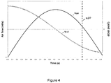
- Figure 4 shows the air flow and the rate of change of air flow for a first puff profile.
- Curve 400 is the air flow rate.
- Curve 410 is the derivation of the air flow with respect to time.
- the threshold for stopping power to the heater can be set at a fixed rate of change of air flow, as illustrated by line 420.
- the rate of change of air flow normalizes between large and small inhalations.
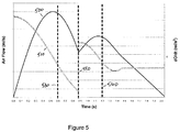
- Figure 5 shows the use of rate of change or air flow for a more complex puff profile.
- Curve 500 is the air flow rate and curve 510 is the rate of change of air flow.
- the power to the heater is stopped when the rate of change of air flow reaches a threshold value.
- the heating power stop will happen several times during the puff, as shown by line 530 and 540.
- the first power stop occurs after 0.6 s.
- the second power stop will appear after 1.2 s.
- the device needs to be reactivated after the first power stop in order to avoid frustrating the user.
- the reactivation threshold can take place at the discontinuity of the derivation curve 550 or when the rate of change of air flow goes positive. Once the air flow falls below the first activation threshold, the device can be reset to provide power again when the air flow exceeds the first activation threshold.
- Q n is the air flow measured at time t n .
- end of puff parameters include Q max /Q, where Q max is the maximum detected air flow during a puff, A/(Q.dQ/dt), AQ max /(Q.dQ/dt) or AT/Q 2 .
- Q max is the maximum detected air flow during a puff
- A/(Q.dQ/dt) is the maximum detected air flow during a puff
- AQ max is the maximum detected air flow during a puff
- Other alternative end of puff parameters include Q max /Q, where Q max is the maximum detected air flow during a puff, A/(Q.dQ/dt), AQ max /(Q.dQ/dt) or AT/Q 2 .
- different end of puff parameters may be appropriate. Whichever end of puff parameter is used it should normalize in some way the different kinds of flow profiles found in user inhalations. This means using a parameter related to the change in air flow over a particular flow period and, as can
- controlling aerosol production in accordance with the present invention can ensure that all of the generated aerosol is delivered to the patient. By stopping aerosol production before the end of an inhalation substantially all of the aerosol is delivered to the patient and so medication dosage can be more accurately monitored.
- a vibrating orifice transducer may be used to generate aerosol.
- the temperature variable used with the heater to calculate the end of puff variable can be replaced by an actuator pressure, power, frequency or amplitude of displacement variables.
Landscapes
- Engineering & Computer Science (AREA)
- Health & Medical Sciences (AREA)
- Anesthesiology (AREA)
- Biomedical Technology (AREA)
- Heart & Thoracic Surgery (AREA)
- Hematology (AREA)
- Life Sciences & Earth Sciences (AREA)
- Animal Behavior & Ethology (AREA)
- General Health & Medical Sciences (AREA)
- Public Health (AREA)
- Veterinary Medicine (AREA)
- General Engineering & Computer Science (AREA)
- Chemical & Material Sciences (AREA)
- Combustion & Propulsion (AREA)
- Mechanical Engineering (AREA)
- Physics & Mathematics (AREA)
- Thermal Sciences (AREA)
- Bioinformatics & Cheminformatics (AREA)
- Pulmonology (AREA)
- Resistance Heating (AREA)
- Flow Control (AREA)
- Pipe Accessories (AREA)
- Feeding, Discharge, Calcimining, Fusing, And Gas-Generation Devices (AREA)
- Disinfection, Sterilisation Or Deodorisation Of Air (AREA)
- Control Of Resistance Heating (AREA)
- Catching Or Destruction (AREA)
- Electrostatic Spraying Apparatus (AREA)
- Spray Control Apparatus (AREA)
- Medicinal Preparation (AREA)
- Feedback Control In General (AREA)
- Cosmetics (AREA)
- Measuring Volume Flow (AREA)
Claims (10)
- Verfahren zum Steuern der Aerosolherstellung in einer Aerosol erzeugenden Vorrichtung (100), wobei die Vorrichtung umfasst:ein Aerosol erzeugendes Element (119);einen Strömungskanal, der konfiguriert ist, einen Luftstrom an dem Aerosol erzeugenden Element vorbei zu ermöglichen; undeinen Strömungssensor (111), der konfiguriert ist, den Luftstrom in dem Strömungskanal zu detektieren, was die Schritte umfasst:Bestimmen eines Wertes eines ersten Parameters, der mit einer Änderung im Volumenstrom des Luftstroms verbunden ist; undÄndern des Lieferns von Strom zu dem Aerosol erzeugenden Element abhängig von einem Resultat eines Vergleichs zwischen dem Wert des ersten Parameters und einem Schwellwert, dadurch gekennzeichnet, dass der erste Parameter aus einer Kombination eines zweiten Parameters, der ein Maß eines Volumenstroms ist, der durch den Strömungssensor detektiert wird, und eines dritten mit dem Volumenstrom verbundenen Parameters abgeleitet ist,und wobei der dritte Parameter Temperatur, Strom, der an das Aerosol erzeugende Element geliefert wird, ein maximaler detektierter Volumenstrom oder eine Änderungsgeschwindigkeit des Volumenstroms ist oder aus einer Kombination von zwei oder mehr von Temperatur, Strom, der an das Aerosol erzeugende Element geliefert wird, einem maximalen detektierten Volumenstrom und einer Änderungsgeschwindigkeit des Volumenstroms abgeleitet ist.
- Verfahren nach Anspruch 1, wobei der dritte Parameter Temperatur oder maximaler Volumenstrom ist, und umfassend einen Schritt des Ableitens des ersten Parameters durch Berechnen eines Verhältnisses zwischen den zweiten und dritten Parametern.
- Verfahren nach Anspruch 1, wobei der dritte Parameter Strom ist, der an das Aerosol erzeugende Element geliefert wird, oder eine Änderungsgeschwindigkeit des Volumenstroms, und weiter umfassend einen Schritt des Ableitens des ersten Parameters durch Berechnen eines Produktes von den zweiten und dritten Parametern.
- Verfahren nach einem der vorstehenden Ansprüche, wobei der erste Parameter eine Änderungsgeschwindigkeit des Volumenstroms ist.
- Verfahren nach einem der vorstehenden Ansprüche, wobei das Aerosol erzeugende Element ein elektrisch beheiztes Heizelement (119) ist und der erste Parameter proportional zu einer Temperatur des Heizelements geteilt durch einen Volumenstrom, der von dem Strömungssensor detektiert wird, ist.
- Verfahren nach einem der vorstehenden Ansprüche, weiter umfassend der Schritt des erneuten Lieferns von Strom an das Aerosol erzeugende Element basierend auf einem Volumenstrom, der von dem Strömungssensor detektiert wird.
- Elektrisch betriebene Aerosol erzeugende Vorrichtung, wobei die Vorrichtung umfasst: mindestens ein elektrisches Aerosol erzeugendes Element (119) zum Bilden eines Aerosols von einem Substrat; eine Stromversorgung (107) zum Liefern von Strom an das mindestens eine Aerosol erzeugende Element; und elektrische Schaltungen (109) zum Steuern des Lieferns von Strom von der Stromversorgung an das mindestens eine Aerosol erzeugende Element, wobei die elektrischen Schaltungen einen Sensor (111) zum Detektieren des Luftstroms an dem Aerosol erzeugenden Element vorbei umfassen, und wobei die elektrischen Schaltungen angeordnet sind:einen Wert eines ersten Parameters zu bestimmen, der mit einer Änderung im Volumenstrom des Luftstroms verbunden ist; unddas Liefern von Strom an das Aerosol erzeugende Element abhängig von einem Resultat eines Vergleichs zwischen dem Wert des ersten Parameters und einem Schwellwert zu reduzieren oder zu Null auszusetzen, dadurch gekennzeichnet, dass der erste Parameter aus einer Kombination eines zweiten Parameters, der ein Maß eines Volumenstroms ist, welcher von dem Strömungssensor detektiert wird, und eines dritten Parameters, der mit dem Volumenstrom verbunden ist, abgeleitet ist,und wobei der dritte Parameter Temperatur, Strom, der an das Aerosol erzeugende Element geliefert wird, ein maximaler detektierter Volumenstrom oder eine Änderungsgeschwindigkeit des Volumenstroms ist oder aus einer Kombination von zwei oder mehr von Temperatur, Strom, der an das Aerosol erzeugende Element geliefert wird, einem maximalen detektierten Volumenstrom und einer Änderungsgeschwindigkeit des Volumenstroms abgeleitet ist.
- Elektrisch betriebene Aerosol erzeugende Vorrichtung nach Anspruch 7, wobei das Aerosol erzeugende Element ein elektrisch beheiztes Heizelement (119) ist und der erste Parameter proportional zu einer Temperatur des Heizelements geteilt durch einen Volumenstrom, der von dem Strömungssensor detektiert wird, ist.
- Computerprogramm, das bei Ausführung auf programmierbaren elektrischen Schaltungen für eine elektrisch betriebene Aerosol erzeugende Vorrichtung die programmierbaren elektrischen Schaltungen veranlasst, das Verfahren nach Anspruch 1 auszuführen.
- Computerlesbares Speichermedium, auf dem ein Computerprogramm nach Anspruch 9 gespeichert ist.
Priority Applications (2)
| Application Number | Priority Date | Filing Date | Title |
|---|---|---|---|
| EP12808691.5A EP2770860B2 (de) | 2011-10-27 | 2012-10-25 | Strombetriebenes aerosolerzeugungssystem mit aerosolherstellungssteuerung |
| RS20160319A RS54741B1 (sr) | 2011-10-27 | 2012-10-25 | Električni sistem za proizvodnju aerosola koji ima kontrolisanu proizvodnju aerosola |
Applications Claiming Priority (3)
| Application Number | Priority Date | Filing Date | Title |
|---|---|---|---|
| EP11250874 | 2011-10-27 | ||
| EP12808691.5A EP2770860B2 (de) | 2011-10-27 | 2012-10-25 | Strombetriebenes aerosolerzeugungssystem mit aerosolherstellungssteuerung |
| PCT/EP2012/071169 WO2013060784A2 (en) | 2011-10-27 | 2012-10-25 | An electrically operated aerosol generating system having aerosol production control |
Publications (3)
| Publication Number | Publication Date |
|---|---|
| EP2770860A2 EP2770860A2 (de) | 2014-09-03 |
| EP2770860B1 true EP2770860B1 (de) | 2016-04-27 |
| EP2770860B2 EP2770860B2 (de) | 2022-06-29 |
Family
ID=47469873
Family Applications (1)
| Application Number | Title | Priority Date | Filing Date |
|---|---|---|---|
| EP12808691.5A Active EP2770860B2 (de) | 2011-10-27 | 2012-10-25 | Strombetriebenes aerosolerzeugungssystem mit aerosolherstellungssteuerung |
Country Status (25)
| Country | Link |
|---|---|
| US (1) | US10247443B2 (de) |
| EP (1) | EP2770860B2 (de) |
| JP (1) | JP6114293B2 (de) |
| KR (1) | KR102081234B1 (de) |
| CN (1) | CN103945716B (de) |
| AR (1) | AR088557A1 (de) |
| AU (1) | AU2012330373B2 (de) |
| BR (1) | BR112014009965B1 (de) |
| CA (1) | CA2853578C (de) |
| DK (1) | DK2770860T3 (de) |
| ES (1) | ES2579127T5 (de) |
| HU (1) | HUE027458T2 (de) |
| IL (1) | IL231908B (de) |
| IN (1) | IN2014DN03135A (de) |
| MX (1) | MX346960B (de) |
| MY (1) | MY167622A (de) |
| PH (1) | PH12014500749A1 (de) |
| PL (1) | PL2770860T5 (de) |
| RS (1) | RS54741B1 (de) |
| RU (1) | RU2605837C2 (de) |
| SG (1) | SG11201401820WA (de) |
| TW (1) | TWI546023B (de) |
| UA (1) | UA112090C2 (de) |
| WO (1) | WO2013060784A2 (de) |
| ZA (1) | ZA201402516B (de) |
Cited By (2)
| Publication number | Priority date | Publication date | Assignee | Title |
|---|---|---|---|---|
| US11051554B2 (en) | 2014-11-12 | 2021-07-06 | Rai Strategic Holdings, Inc. | MEMS-based sensor for an aerosol delivery device |
| EP3871527B1 (de) * | 2018-10-26 | 2025-12-17 | Japan Tobacco Inc. | Steuereinheit, aerosolerzeugungsvorrichtung, verfahren und programm zur steuerung des heizaggregats |
Families Citing this family (177)
| Publication number | Priority date | Publication date | Assignee | Title |
|---|---|---|---|---|
| US10244793B2 (en) | 2005-07-19 | 2019-04-02 | Juul Labs, Inc. | Devices for vaporization of a substance |
| GB2502053B (en) | 2012-05-14 | 2014-09-24 | Nicoventures Holdings Ltd | Electronic smoking device |
| GB2502055A (en) | 2012-05-14 | 2013-11-20 | Nicoventures Holdings Ltd | Modular electronic smoking device |
| GB2504076A (en) | 2012-07-16 | 2014-01-22 | Nicoventures Holdings Ltd | Electronic smoking device |
| GB2504075A (en) | 2012-07-16 | 2014-01-22 | Nicoventures Holdings Ltd | Electronic smoking device |
| GB2507104A (en) * | 2012-10-19 | 2014-04-23 | Nicoventures Holdings Ltd | Electronic inhalation device |
| GB2507103A (en) | 2012-10-19 | 2014-04-23 | Nicoventures Holdings Ltd | Electronic inhalation device |
| TWI608805B (zh) * | 2012-12-28 | 2017-12-21 | 菲利浦莫里斯製品股份有限公司 | 加熱型氣溶膠產生裝置及用於產生具有一致性質的氣溶膠之方法 |
| US9423152B2 (en) * | 2013-03-15 | 2016-08-23 | R. J. Reynolds Tobacco Company | Heating control arrangement for an electronic smoking article and associated system and method |
| PL2999365T3 (pl) | 2013-05-21 | 2021-04-19 | Philip Morris Products S.A. | Układ dostarczania aerozolu z grzaniem elektrycznym |
| GB2518598B (en) | 2013-08-30 | 2016-06-01 | Nicoventures Holdings Ltd | Apparatus with battery power control |
| RU2629878C1 (ru) * | 2013-09-30 | 2017-09-04 | Джапан Тобакко Инк. | Ароматический ингалятор негорящего типа |
| WO2015046420A1 (ja) | 2013-09-30 | 2015-04-02 | 日本たばこ産業株式会社 | 非燃焼型香味吸引器 |
| GB2519101A (en) * | 2013-10-09 | 2015-04-15 | Nicoventures Holdings Ltd | Electronic vapour provision system |
| US10039321B2 (en) | 2013-11-12 | 2018-08-07 | Vmr Products Llc | Vaporizer |
| US20160366947A1 (en) | 2013-12-23 | 2016-12-22 | James Monsees | Vaporizer apparatus |
| US10159282B2 (en) | 2013-12-23 | 2018-12-25 | Juul Labs, Inc. | Cartridge for use with a vaporizer device |
| USD842536S1 (en) | 2016-07-28 | 2019-03-05 | Juul Labs, Inc. | Vaporizer cartridge |
| US10076139B2 (en) | 2013-12-23 | 2018-09-18 | Juul Labs, Inc. | Vaporizer apparatus |
| US10058129B2 (en) | 2013-12-23 | 2018-08-28 | Juul Labs, Inc. | Vaporization device systems and methods |
| KR102267997B1 (ko) * | 2013-12-23 | 2021-06-23 | 쥴 랩스, 인크. | 기화 디바이스 시스템 및 방법 |
| US12279646B2 (en) | 2014-02-06 | 2025-04-22 | Juul Labs, Inc. | Cartridge of vaporization device systems having unequal transverse cartridge dimensions |
| TWI751467B (zh) | 2014-02-06 | 2022-01-01 | 美商尤爾實驗室有限公司 | 產生可吸入氣膠之裝置及用於該裝置之可分離匣 |
| US10081531B2 (en) | 2014-02-28 | 2018-09-25 | Beyond Twenty Ltd. | Electronic vaporiser system |
| US12295411B2 (en) | 2014-02-28 | 2025-05-13 | Ayr Ltd. | Electronic vaporizer system |
| GB201413032D0 (en) | 2014-02-28 | 2014-09-03 | Beyond Twenty Ltd | Beyond 7 |
| US11085550B2 (en) | 2014-02-28 | 2021-08-10 | Ayr Ltd. | Electronic vaporiser system |
| US10588176B2 (en) | 2014-02-28 | 2020-03-10 | Ayr Ltd. | Electronic vaporiser system |
| US10285430B2 (en) | 2014-02-28 | 2019-05-14 | Ayr Ltd. | Electronic vaporiser system |
| US10091839B2 (en) | 2014-02-28 | 2018-10-02 | Beyond Twenty Ltd. | Electronic vaporiser system |
| PL2915443T3 (pl) * | 2014-03-03 | 2020-01-31 | Fontem Holdings 1 B.V. | Elektroniczne urządzenie do palenia |
| US11696604B2 (en) * | 2014-03-13 | 2023-07-11 | Rai Strategic Holdings, Inc. | Aerosol delivery device and related method and computer program product for controlling an aerosol delivery device based on input characteristics |
| MY189739A (en) * | 2014-05-02 | 2022-02-28 | Japan Tobacco Inc | Non-burning-type flavor inhaler |
| ES2703350T5 (es) * | 2014-05-12 | 2024-07-10 | Philip Morris Products Sa | Dispositivo vaporizador mejorado |
| GB201410171D0 (en) | 2014-06-09 | 2014-07-23 | Nicoventures Holdings Ltd | Electronic vapour provision system |
| GB2528673B (en) | 2014-07-25 | 2020-07-01 | Nicoventures Holdings Ltd | Aerosol provision system |
| CA160775S (en) | 2014-08-11 | 2015-09-29 | Ploom Inc | Electronic vaporization device with cartridge |
| ES2688176T3 (es) | 2014-10-24 | 2018-10-31 | Philip Morris Products S.A. | Método, sistema y dispositivo generador de aerosol con un detector de gas de combustión |
| US10557628B2 (en) * | 2014-11-10 | 2020-02-11 | Sevak Isayan | Handheld vaporizer |
| US20160150828A1 (en) * | 2014-12-02 | 2016-06-02 | Gabriel Marc Goldstein | Vaporizing reservoir |
| KR102627987B1 (ko) | 2014-12-05 | 2024-01-22 | 쥴 랩스, 인크. | 교정된 투여량 제어 |
| CA2970401C (en) * | 2014-12-11 | 2023-06-13 | Michel Thorens | Inhaling device with user recognition based on inhalation behaviour |
| JP6771465B2 (ja) | 2014-12-15 | 2020-10-21 | フィリップ・モーリス・プロダクツ・ソシエテ・アノニム | エアロゾルの特性を制御するためのエアロゾルの生成を制御する方法 |
| US20160255828A1 (en) * | 2015-03-06 | 2016-09-08 | Luis Alberto Cestino | Portable hand-held device for emitting a volatile substance |
| EA034186B1 (ru) * | 2015-03-10 | 2020-01-15 | Джапан Тобакко Инк. | Способ производства блока распыления, ингалятор ароматического вещества невоспламеняющегося типа, блок распыления и комплект блока распыления |
| US10172388B2 (en) * | 2015-03-10 | 2019-01-08 | Rai Strategic Holdings, Inc. | Aerosol delivery device with microfluidic delivery component |
| US10179215B2 (en) | 2015-03-19 | 2019-01-15 | Altria Client Services Llc | Vaporizer for vaporizing a constituent of a plant material |
| US10765821B2 (en) | 2015-03-19 | 2020-09-08 | Altria Client Services Llc | Vaporizer for vaporizing a constituent of a plant material |
| GB201505597D0 (en) | 2015-03-31 | 2015-05-13 | British American Tobacco Co | Article for use with apparatus for heating smokable material |
| GB201505595D0 (en) | 2015-03-31 | 2015-05-13 | British American Tobacco Co | Cartridge for use with apparatus for heating smokeable material |
| WO2016175320A1 (ja) * | 2015-04-30 | 2016-11-03 | 日本たばこ産業株式会社 | 非燃焼型香味吸引器 |
| CN107645913B (zh) | 2015-05-26 | 2020-07-31 | 菲利普莫里斯生产公司 | 控制气溶胶生成系统 |
| JP6395931B2 (ja) * | 2015-05-29 | 2018-09-26 | 日本たばこ産業株式会社 | 非燃焼型香味吸引器及びエアロゾル送達方法 |
| UA123205C2 (uk) * | 2015-06-29 | 2021-03-03 | Філіп Морріс Продактс С.А. | Картридж і пристрій для системи, що генерує аерозоль |
| PL3313216T3 (pl) * | 2015-06-29 | 2019-07-31 | Philip Morris Products S.A. | Wkład do układu wytwarzania aerozolu |
| CN107847184B (zh) * | 2015-06-30 | 2021-01-22 | 皇家飞利浦有限公司 | 用于医学喷雾剂递送设备的控制设备 |
| CA2986339A1 (en) | 2015-06-30 | 2017-01-05 | Philip Morris Products S.A. | An aerosol-generating device, system and method with a heated gas sensor |
| GB2540135B (en) | 2015-07-01 | 2021-03-03 | Nicoventures Holdings Ltd | Electronic aerosol provision system |
| US10015987B2 (en) * | 2015-07-24 | 2018-07-10 | Rai Strategic Holdings Inc. | Trigger-based wireless broadcasting for aerosol delivery devices |
| CN108136141B (zh) | 2015-09-01 | 2021-09-03 | 艾尔有限公司 | 电子蒸发器系统 |
| GB2542009B (en) * | 2015-09-01 | 2020-01-15 | Ayr Ltd | Electronic vaporiser system |
| JP6847926B2 (ja) | 2015-09-16 | 2021-03-24 | フィリップ・モーリス・プロダクツ・ソシエテ・アノニム | 可撓性の壁を有する液体貯蔵部分を有するカートリッジ |
| JP6847928B2 (ja) | 2015-09-16 | 2021-03-24 | フィリップ・モーリス・プロダクツ・ソシエテ・アノニム | 静電容量センサを有するカートリッジ |
| GB201517089D0 (en) | 2015-09-28 | 2015-11-11 | Nicoventures Holdings Ltd | Vaping heat map system and method for electronic vapour provision systems |
| PL3155910T3 (pl) | 2015-10-16 | 2020-12-28 | Fontem Holdings 1 B.V. | Elektroniczne urządzenie do palenia z dwoma równoległymi ścieżkami przepływu o stałym całkowitym oporze przepływu |
| KR102661607B1 (ko) * | 2015-11-02 | 2024-04-30 | 필립모리스 프로덕츠 에스.에이. | 진동 부재를 포함하는 에어로졸 발생 시스템 |
| US10820630B2 (en) | 2015-11-06 | 2020-11-03 | Rai Strategic Holdings, Inc. | Aerosol delivery device including a wirelessly-heated atomizer and related method |
| WO2017084818A1 (en) | 2015-11-17 | 2017-05-26 | Philip Morris Products S.A. | Aerosol-generating system with self-activated electric heater |
| US10194694B2 (en) * | 2016-01-05 | 2019-02-05 | Rai Strategic Holdings, Inc. | Aerosol delivery device with improved fluid transport |
| CN120586220A (zh) | 2016-01-11 | 2025-09-05 | Syqe医药有限公司 | 个人用蒸发装置 |
| US10104912B2 (en) * | 2016-01-20 | 2018-10-23 | Rai Strategic Holdings, Inc. | Control for an induction-based aerosol delivery device |
| KR102698646B1 (ko) | 2016-02-01 | 2024-08-27 | 필립모리스 프로덕츠 에스.에이. | 다수의 전력 공급부를 갖는 에어로졸 발생 장치 |
| MX377347B (es) | 2016-02-11 | 2025-03-07 | Juul Labs Inc | Cartucho rellenable de vaporizador y metodo de relleno |
| WO2017139675A1 (en) | 2016-02-11 | 2017-08-17 | Pax Labs, Inc. | Securely attaching cartridges for vaporizer devices |
| KR102773870B1 (ko) | 2016-02-19 | 2025-02-28 | 필립모리스 프로덕츠 에스.에이. | 사용 방식 결정 기능을 구비한 에어로졸 발생 시스템 |
| CN108430244B (zh) | 2016-02-25 | 2021-07-16 | 菲利普莫里斯生产公司 | 具有温度传感器的电操作气溶胶生成系统 |
| EP3419445B1 (de) | 2016-02-25 | 2022-11-09 | Philip Morris Products S.A. | Aerosolerzeugungssystem mit flüssigkeitsfüllstandsbestimmung und verfahren zur bestimmung des flüssigkeitsfüllstands in einem aerosolerzeugungssystem |
| CN108697166B (zh) | 2016-02-25 | 2022-06-07 | 菲利普莫里斯生产公司 | 具有倾斜传感器的电操作气溶胶生成系统 |
| US10912333B2 (en) | 2016-02-25 | 2021-02-09 | Juul Labs, Inc. | Vaporization device control systems and methods |
| EP3423135A1 (de) | 2016-02-29 | 2019-01-09 | Emplicure AB | Vorrichtungen zur verdampfung und inhalation von nikotin |
| JP6957511B2 (ja) * | 2016-05-31 | 2021-11-02 | フィリップ・モーリス・プロダクツ・ソシエテ・アノニム | 側面のくぼみを有するエアロゾル発生装置 |
| USD849996S1 (en) | 2016-06-16 | 2019-05-28 | Pax Labs, Inc. | Vaporizer cartridge |
| USD836541S1 (en) | 2016-06-23 | 2018-12-25 | Pax Labs, Inc. | Charging device |
| USD851830S1 (en) | 2016-06-23 | 2019-06-18 | Pax Labs, Inc. | Combined vaporizer tamp and pick tool |
| US11147315B2 (en) * | 2016-07-25 | 2021-10-19 | Fontem Holdings 1 B.V. | Controlling an operation of an electronic cigarette |
| GB201612945D0 (en) * | 2016-07-26 | 2016-09-07 | British American Tobacco Investments Ltd | Method of generating aerosol |
| US10729177B2 (en) * | 2016-07-31 | 2020-08-04 | Altria Client Services Llc | Electronic vaping device, battery section, and charger |
| AU2017307602B2 (en) * | 2016-08-05 | 2023-04-06 | Juul Labs, Inc. | Anemometric-assisted control of a vaporizer |
| US10765146B2 (en) * | 2016-08-08 | 2020-09-08 | Rai Strategic Holdings, Inc. | Boost converter for an aerosol delivery device |
| DE102016114718B4 (de) * | 2016-08-09 | 2021-02-25 | Hauni Maschinenbau Gmbh | Inhalator |
| US10524509B2 (en) | 2016-11-18 | 2020-01-07 | Rai Strategic Holdings, Inc. | Pressure sensing for an aerosol delivery device |
| JP6995854B2 (ja) | 2016-12-19 | 2022-01-17 | フィリップ・モーリス・プロダクツ・ソシエテ・アノニム | カートリッジおよびバイパス空気吸込み口を有するエアロゾル発生システム |
| EP3562342B1 (de) * | 2016-12-30 | 2025-07-30 | JT International S.A. | Elektrisch betriebenes aerosolerzeugungssystem |
| EP4118989A1 (de) * | 2017-01-18 | 2023-01-18 | KT&G Corporation | Feinpartikelerzeugungsvorrichtung |
| CN108338417B (zh) * | 2017-01-25 | 2022-05-27 | 贵州中烟工业有限责任公司 | 基于微加热器的电加热吸烟系统 |
| CN108338416B (zh) * | 2017-01-25 | 2022-05-31 | 贵州中烟工业有限责任公司 | 内芯式加热吸烟系统 |
| CN108338414B (zh) * | 2017-01-25 | 2022-05-27 | 贵州中烟工业有限责任公司 | 电加热吸烟系统的控制方法和控制系统 |
| CN108338415B (zh) * | 2017-01-25 | 2022-05-31 | 贵州中烟工业有限责任公司 | 外围式加热吸烟系统 |
| US10219544B2 (en) * | 2017-03-24 | 2019-03-05 | Rai Strategic Holdings, Inc. | Aerosol delivery device and a related method |
| EA201991564A1 (ru) * | 2017-04-24 | 2019-09-30 | Джапан Тобакко Инк. | Генерирующее аэрозоль устройство, способ управления генерирующим аэрозоль устройством и программа |
| WO2018198154A1 (ja) | 2017-04-24 | 2018-11-01 | 日本たばこ産業株式会社 | エアロゾル生成装置並びにエアロゾル生成装置の制御方法及びプログラム |
| CN110430768A (zh) * | 2017-04-24 | 2019-11-08 | 日本烟草产业株式会社 | 气溶胶生成装置以及气溶胶生成装置的控制方法及程序 |
| GB201709201D0 (en) * | 2017-06-09 | 2017-07-26 | Nicoventures Holdings Ltd | Electronic aerosol provision system |
| CN110731125B (zh) * | 2017-06-30 | 2022-04-15 | 菲利普莫里斯生产公司 | 用于气溶胶生成系统的感应加热装置 |
| WO2019011623A1 (en) * | 2017-07-10 | 2019-01-17 | Philip Morris Products S.A. | CONTROL FOR PRODUCTION OF TOTAL PARTICULATE MATTER |
| KR102569256B1 (ko) | 2017-08-09 | 2023-08-22 | 필립모리스 프로덕츠 에스.에이. | 감소된 분리를 갖는 인덕터 코일을 갖는 에어로졸 발생 장치 |
| USD887632S1 (en) | 2017-09-14 | 2020-06-16 | Pax Labs, Inc. | Vaporizer cartridge |
| US11039645B2 (en) | 2017-09-19 | 2021-06-22 | Rai Strategic Holdings, Inc. | Differential pressure sensor for an aerosol delivery device |
| EA202090952A1 (ru) * | 2017-10-24 | 2020-10-23 | Джапан Тобакко Инк. | Аэрозоль-генерирующее устройство |
| JP6780907B2 (ja) * | 2017-10-24 | 2020-11-04 | 日本たばこ産業株式会社 | エアロゾル生成装置並びにこれを動作させる方法及びプログラム |
| US10806181B2 (en) * | 2017-12-08 | 2020-10-20 | Rai Strategic Holdings, Inc. | Quasi-resonant flyback converter for an induction-based aerosol delivery device |
| CN107997239A (zh) * | 2017-12-13 | 2018-05-08 | 惠州市吉瑞科技有限公司深圳分公司 | 气溶胶发生装置及其控制方法、应用于气溶胶发生装置的微处理器 |
| GB201721821D0 (en) | 2017-12-22 | 2018-02-07 | Nicoventures Holdings Ltd | Electronic aerosol provision system |
| CN119097122A (zh) | 2018-02-27 | 2024-12-10 | 尤尔实验室有限公司 | 质量输出受控的蒸发器 |
| EP3536177B1 (de) * | 2018-03-07 | 2021-07-14 | Fontem Holdings 1 B.V. | Elektronische rauchvorrichtung mit flüssigkeitspumpe |
| JP6913193B2 (ja) * | 2018-04-19 | 2021-08-04 | 日本たばこ産業株式会社 | カートリッジ及び非燃焼型香味吸引器 |
| US11986016B2 (en) | 2018-04-24 | 2024-05-21 | Philip Morris Products S.A. | Inductive heating assembly for aerosol generation comprising a susceptor element and a liquid retention element |
| GB201806826D0 (en) | 2018-04-26 | 2018-06-13 | Nicoventures Trading Ltd | Electronic aerosol provision system and method |
| CN109043665B (zh) * | 2018-05-25 | 2020-12-15 | 威滔电子科技(深圳)有限公司 | 一种控制气溶胶产生的方法及装置 |
| DE102018127927A1 (de) * | 2018-05-28 | 2019-11-28 | Hauni Maschinenbau Gmbh | Anordnung und Basisteil für einen Inhalator, und Inhalator |
| MY206004A (en) | 2018-06-21 | 2024-11-23 | Philip Morris Products Sa | Improved control of aerosol production in an aerosol-generating system |
| RU2754843C1 (ru) * | 2018-06-22 | 2021-09-08 | Джапан Тобакко Инк. | Аэрозольное устройство, а также способ и компьютерно-читаемый носитель данных, содержащий программу для управления таким устройством |
| KR102389828B1 (ko) * | 2018-07-04 | 2022-04-22 | 주식회사 케이티앤지 | 에어로졸 생성 장치 및 이를 제어하는 방법 |
| JP2021528955A (ja) * | 2018-07-26 | 2021-10-28 | フィリップ・モーリス・プロダクツ・ソシエテ・アノニム | エアロゾルを発生させるためのシステム |
| US20200035118A1 (en) | 2018-07-27 | 2020-01-30 | Joseph Pandolfino | Methods and products to facilitate smokers switching to a tobacco heating product or e-cigarettes |
| US10897925B2 (en) | 2018-07-27 | 2021-01-26 | Joseph Pandolfino | Articles and formulations for smoking products and vaporizers |
| US10721971B2 (en) | 2018-09-18 | 2020-07-28 | Airgraft Inc. | Methods and systems for vaporizer security and traceability management |
| CN119279271A (zh) | 2018-09-28 | 2025-01-10 | 菲利普莫里斯生产公司 | 气溶胶生成装置 |
| EP3863436B1 (de) | 2018-10-08 | 2024-12-04 | Juul Labs, Inc. | Kartusche für eine verdampfervorrichtung und verdampfervorrichtung |
| GB201818007D0 (en) | 2018-11-05 | 2018-12-19 | Nicoventures Trading Ltd | Device calibration and method |
| EP4537877A3 (de) | 2018-11-05 | 2025-06-04 | Juul Labs, Inc. | Kartuschen für verdampfervorrichtungen |
| EP3876760B1 (de) | 2018-11-08 | 2024-05-15 | Juul Labs, Inc. | Kartuschen für verdampfergeräte |
| WO2020126908A1 (en) * | 2018-12-17 | 2020-06-25 | Philip Morris Products S.A. | Aerosol-generating device with mouthpiece detection |
| JP6522847B1 (ja) * | 2018-12-19 | 2019-05-29 | 日本たばこ産業株式会社 | エアロゾル吸引器、これ用の制御装置、これの制御方法並びにこれ用の制御装置の動作方法及びプログラム |
| CN109619695A (zh) * | 2019-01-28 | 2019-04-16 | 深圳市卓力能电子有限公司 | 一种气溶胶发生装置及其控制方法 |
| EP3711550A1 (de) * | 2019-03-22 | 2020-09-23 | Nerudia Limited | Rauchersatzsystem |
| JP6621554B2 (ja) * | 2019-03-28 | 2019-12-18 | 日本たばこ産業株式会社 | 非燃焼型香味吸引器 |
| JP6621557B2 (ja) * | 2019-03-28 | 2019-12-18 | 日本たばこ産業株式会社 | 非燃焼型香味吸引器 |
| JP6621556B2 (ja) * | 2019-03-28 | 2019-12-18 | 日本たばこ産業株式会社 | 非燃焼型香味吸引器 |
| JP6621555B2 (ja) * | 2019-03-28 | 2019-12-18 | 日本たばこ産業株式会社 | 非燃焼型香味吸引器 |
| US11458262B2 (en) | 2019-06-25 | 2022-10-04 | Altria Client Services Llc | Capsules, heat-not-burn (HNB) aerosol-generating devices, and methods of generating an aerosol |
| USD916361S1 (en) | 2019-06-25 | 2021-04-13 | Altria Client Services Llc | Aerosol-generating capsule |
| KR102278593B1 (ko) * | 2019-07-29 | 2021-07-16 | 주식회사 케이티앤지 | 에어로졸 생성 장치 및 이의 동작 방법 |
| CN110584204B (zh) * | 2019-07-30 | 2023-06-02 | 深圳麦克韦尔科技有限公司 | 电子雾化装置的加热控制方法、控制装置及电子雾化装置 |
| WO2021026660A1 (en) | 2019-08-13 | 2021-02-18 | Airgraft Inc. | Methods and systems for heating carrier material using a vaporizer |
| CN112438437B (zh) | 2019-09-03 | 2022-12-20 | 深圳市合元科技有限公司 | 气溶胶生成系统、检测方法、雾化装置和电源装置 |
| GB201914947D0 (en) * | 2019-10-16 | 2019-11-27 | Nicoventures Trading Ltd | Electronic aerosol provision system and method |
| GB201914945D0 (en) * | 2019-10-16 | 2019-11-27 | Nicoventures Trading Ltd | Electronic aerosol provision system and method |
| JP6678807B2 (ja) * | 2019-11-15 | 2020-04-08 | 日本たばこ産業株式会社 | 非燃焼型香味吸引器及びエアロゾル送達方法 |
| KR102318695B1 (ko) * | 2019-12-23 | 2021-10-27 | 주식회사 케이티앤지 | 다중 히터를 구비한 에어로졸 발생 장치 및 그의 제어 방법 |
| KR102350596B1 (ko) * | 2020-01-16 | 2022-01-14 | 주식회사 케이티앤지 | 에어로졸 생성 장치 |
| KR102324197B1 (ko) | 2020-02-07 | 2021-11-09 | 주식회사 케이티앤지 | 에어로졸 생성 장치 |
| KR102419147B1 (ko) * | 2020-03-13 | 2022-07-08 | 주식회사 케이티앤지 | 비정상적인 동작을 판단하는 에어로졸 생성 장치 |
| JP6735943B2 (ja) * | 2020-03-13 | 2020-08-05 | 日本たばこ産業株式会社 | 非燃焼型香味吸引器 |
| JP6737972B2 (ja) * | 2020-03-13 | 2020-08-12 | 日本たばこ産業株式会社 | 非燃焼型香味吸引器 |
| JP6737971B2 (ja) * | 2020-03-13 | 2020-08-12 | 日本たばこ産業株式会社 | 非燃焼型香味吸引器 |
| US11730196B2 (en) | 2020-07-15 | 2023-08-22 | Altria Client Services Llc | Nicotine electronic vaping device including a reservoir assembly |
| US11653704B2 (en) | 2020-07-15 | 2023-05-23 | Altria Client Services Llc | Heating engine control circuits and nicotine electronic vaping devices including the same |
| US11666101B2 (en) | 2020-07-15 | 2023-06-06 | Altria Client Services Llc | Heating engine control circuits and non-nicotine electronic vaping devices including the same |
| US20220015420A1 (en) * | 2020-07-15 | 2022-01-20 | Altria Client Services Llc | Non-nicotine electronic vaping device including a reservoir assembly |
| US12193502B2 (en) | 2020-12-30 | 2025-01-14 | Altria Client Services Llc | Capsules including embedded corrugated heater, heat-not-burn (HNB) aerosol-generating devices, and methods of generating an aerosol |
| US12053022B2 (en) | 2021-01-04 | 2024-08-06 | Altria Client Services Llc | Capsules with integrated mouthpieces, heat-not-burn (HNB) aerosol-generating devices, and methods of generating an aerosol |
| USD1095794S1 (en) | 2021-01-18 | 2025-09-30 | Altria Client Services Llc | Aerosol-generating capsule |
| US12520880B2 (en) | 2021-01-18 | 2026-01-13 | Altria Client Services Llc | Heat-not-burn (HNB) aerosol-generating devices including energy based heater control, and methods of controlling a heater |
| US11910826B2 (en) | 2021-01-18 | 2024-02-27 | Altria Client Services Llc | Heat-not-burn (HNB) aerosol-generating devices and capsules |
| US12569008B2 (en) | 2021-01-18 | 2026-03-10 | Altria Client Services Llc | Heat-not-burn (HNB) aerosol generating devices and capsules |
| US12011034B2 (en) | 2021-01-18 | 2024-06-18 | Altria Client Services Llc | Capsules including embedded heaters and heat-not-burn (HNB) aerosol-generating devices |
| US12201148B2 (en) | 2021-01-18 | 2025-01-21 | Altria Client Services Llc | Closed system capsule with airflow, heat-not-burn (HNB) aerosol-generating devices, and methods of generating an aerosol |
| US12274295B2 (en) | 2021-01-18 | 2025-04-15 | Altria Client Services Llc | Heat-not-burn (HNB) aerosol-generating devices and capsules |
| US11789476B2 (en) | 2021-01-18 | 2023-10-17 | Altria Client Services Llc | Heat-not-burn (HNB) aerosol-generating devices including intra-draw heater control, and methods of controlling a heater |
| JP2021065238A (ja) * | 2021-01-27 | 2021-04-30 | 日本たばこ産業株式会社 | エアロゾル生成装置並びにエアロゾル生成装置の制御方法及びプログラム |
| GB202104639D0 (en) * | 2021-03-31 | 2021-05-12 | Nicoventures Trading Ltd | Aerosol provision system |
| EP4147594B1 (de) * | 2021-04-13 | 2025-02-26 | Shenzhen Smoore Technology Limited | Heizsteuerungsverfahren und elektronische zerstäubungsvorrichtung |
| US12127592B2 (en) | 2021-09-20 | 2024-10-29 | Altria Client Services Llc | Capsule validation for heat-not-burn (HNB) aerosol-generating devices |
| CN117617594A (zh) * | 2022-08-16 | 2024-03-01 | 海南摩尔兄弟科技有限公司 | 电子雾化装置、电源组件、雾化器的控制方法及存储介质 |
| CN116649651A (zh) * | 2023-05-18 | 2023-08-29 | 深圳市赛尔美电子科技有限公司 | 一种气雾发生装置的安装方法及治具 |
| EP4529789A1 (de) * | 2023-09-29 | 2025-04-02 | Imperial Tobacco Limited | Aerosolerzeugungsvorrichtung und verfahren zur steuerung einer aerosolerzeugungsvorrichtung |
Citations (8)
| Publication number | Priority date | Publication date | Assignee | Title |
|---|---|---|---|---|
| WO1992007599A1 (en) | 1990-10-25 | 1992-05-14 | Minnesota Mining And Manufacturing Company | Inhalation device |
| US6584971B1 (en) | 1999-01-04 | 2003-07-01 | Medic-Aid Limited | Drug delivery apparatus |
| US6971383B2 (en) | 2001-01-24 | 2005-12-06 | University Of North Carolina At Chapel Hill | Dry powder inhaler devices, multi-dose dry powder drug packages, control systems, and associated methods |
| US7106955B2 (en) | 1999-08-23 | 2006-09-12 | Fisher & Paykel Healthcare Limited | Humidity controller |
| US20070125370A1 (en) | 2002-11-20 | 2007-06-07 | Denyer Jonathan S H | Inhalation method and apparatus |
| WO2009013504A2 (en) | 2007-07-24 | 2009-01-29 | Respironics Respiratory Drug Delivery (Uk) Ltd. | Apparatus and method for maintaining consistency for aerosol drug delivery treatments |
| WO2011033396A2 (en) | 2009-09-18 | 2011-03-24 | Minilogic Device Corporation Ltd. | Electronic smoke |
| WO2011050964A1 (en) | 2009-10-29 | 2011-05-05 | Philip Morris Products S.A. | An electrically heated smoking system with improved heater |
Family Cites Families (34)
| Publication number | Priority date | Publication date | Assignee | Title |
|---|---|---|---|---|
| US3128764A (en) * | 1960-10-06 | 1964-04-14 | Wilbur R Koehn | Anesthesizing apparatus |
| US3584621A (en) * | 1968-10-31 | 1971-06-15 | Bird F M | Respiratory apparatus |
| US5095921A (en) | 1990-11-19 | 1992-03-17 | Philip Morris Incorporated | Flavor generating article |
| US6540154B1 (en) * | 1991-04-24 | 2003-04-01 | Aerogen, Inc. | Systems and methods for controlling fluid feed to an aerosol generator |
| US5970973A (en) * | 1993-01-29 | 1999-10-26 | Aradigm Corporation | Method of delivering insulin lispro |
| US5372148A (en) * | 1993-02-24 | 1994-12-13 | Philip Morris Incorporated | Method and apparatus for controlling the supply of energy to a heating load in a smoking article |
| US6675797B1 (en) * | 1993-11-05 | 2004-01-13 | Resmed Limited | Determination of patency of the airway |
| EP1488743A3 (de) * | 1993-11-05 | 2005-01-12 | Resmed Limited | Steuerung für die CPAP Behandlung |
| US6040560A (en) * | 1996-10-22 | 2000-03-21 | Philip Morris Incorporated | Power controller and method of operating an electrical smoking system |
| US6234167B1 (en) * | 1998-10-14 | 2001-05-22 | Chrysalis Technologies, Incorporated | Aerosol generator and methods of making and using an aerosol generator |
| GB2343122B (en) † | 1998-10-26 | 2003-01-08 | Medic Aid Ltd | Improvements in and relating to nebulisers |
| GB9924158D0 (en) † | 1999-10-12 | 1999-12-15 | Lifecare Designs Limited | Nebuliser |
| ES2473591T3 (es) * | 2001-07-31 | 2014-07-07 | Philip Morris Products S.A. | Método y aparato para generar líquidos volatilizados |
| WO2003059424A1 (en) | 2002-01-15 | 2003-07-24 | Aerogen, Inc. | Methods and systems for operating an aerosol generator |
| EP1474198B1 (de) * | 2002-01-15 | 2015-12-30 | Novartis AG | System zur entfernung von aerosolen aus dem wirksamen anatomischen totraum |
| RU2311859C2 (ru) | 2002-05-13 | 2007-12-10 | Тинк! Глобал Б.В. | Ингалятор |
| ES2357566T3 (es) * | 2002-09-06 | 2011-04-27 | Philip Morris Usa Inc. | Dispositivos generadores de aerosol y métodos para generar aerosoles con tamaños de partículas controlados. |
| WO2004022128A2 (en) * | 2002-09-06 | 2004-03-18 | Chrysalis Technologies Incorporated | Liquid aerosol formulations and aerosol generating devices and methods for generating aerosols |
| CN100381082C (zh) | 2003-03-14 | 2008-04-16 | 韩力 | 一种非可燃性电子雾化香烟 |
| CN100381083C (zh) * | 2003-04-29 | 2008-04-16 | 韩力 | 一种非可燃性电子喷雾香烟 |
| US7683029B2 (en) * | 2003-05-07 | 2010-03-23 | Philip Morris Usa Inc. | Liquid aerosol formulations containing insulin and aerosol generating devices and methods for generating aerosolized insulin |
| JP2005034021A (ja) * | 2003-07-17 | 2005-02-10 | Seiko Epson Corp | 電子タバコ |
| US7115097B2 (en) * | 2003-10-09 | 2006-10-03 | Johnson Joseph L | Positive airway pressure notification system for treatment of breathing disorders during sleep |
| US7167776B2 (en) * | 2004-09-02 | 2007-01-23 | Philip Morris Usa Inc. | Method and system for controlling a vapor generator |
| WO2006084921A1 (es) * | 2005-02-03 | 2006-08-17 | Zobele España, S.A. | Difusor de sustancias volátiles multifragancia |
| WO2006102707A1 (en) * | 2005-04-01 | 2006-10-05 | Resmed Limited | Ventless mask cpap system |
| JP2008035742A (ja) | 2006-08-03 | 2008-02-21 | British American Tobacco Pacific Corporation | 揮発装置 |
| US7726320B2 (en) | 2006-10-18 | 2010-06-01 | R. J. Reynolds Tobacco Company | Tobacco-containing smoking article |
| CN101678189A (zh) * | 2007-05-07 | 2010-03-24 | 帝人制药株式会社 | 氧浓缩装置 |
| US8978652B2 (en) | 2007-11-14 | 2015-03-17 | Maquet Critical Care Ab | Anesthetic breathing apparatus having improved monitoring of anesthetic agent |
| EP2113178A1 (de) | 2008-04-30 | 2009-11-04 | Philip Morris Products S.A. | Elektrisch beheiztes Rauchsystem mit einem Element zur Flüssigkeitsspeicherung |
| EP2320977B1 (de) | 2008-07-30 | 2017-09-13 | Genericus, Inc. | Inline-verdampfer |
| EP2355882A4 (de) * | 2008-11-10 | 2014-07-23 | Chart Sequal Technologies Inc | Medizinisches beatmungsgerätesystem und verfahren unter einsatz von sauerstoffkonzentratoren |
| CN101518361B (zh) | 2009-03-24 | 2010-10-06 | 北京格林世界科技发展有限公司 | 高仿真电子烟 |
-
2012
- 2012-10-24 TW TW101139223A patent/TWI546023B/zh not_active IP Right Cessation
- 2012-10-25 US US14/354,316 patent/US10247443B2/en active Active
- 2012-10-25 PL PL12808691.5T patent/PL2770860T5/pl unknown
- 2012-10-25 WO PCT/EP2012/071169 patent/WO2013060784A2/en not_active Ceased
- 2012-10-25 ES ES12808691T patent/ES2579127T5/es active Active
- 2012-10-25 EP EP12808691.5A patent/EP2770860B2/de active Active
- 2012-10-25 UA UAA201404835A patent/UA112090C2/uk unknown
- 2012-10-25 SG SG11201401820WA patent/SG11201401820WA/en unknown
- 2012-10-25 MX MX2014005084A patent/MX346960B/es active IP Right Grant
- 2012-10-25 CA CA2853578A patent/CA2853578C/en not_active Expired - Fee Related
- 2012-10-25 CN CN201280055759.9A patent/CN103945716B/zh active Active
- 2012-10-25 DK DK12808691.5T patent/DK2770860T3/en active
- 2012-10-25 HU HUE12808691A patent/HUE027458T2/en unknown
- 2012-10-25 RS RS20160319A patent/RS54741B1/sr unknown
- 2012-10-25 PH PH1/2014/500749A patent/PH12014500749A1/en unknown
- 2012-10-25 JP JP2014537618A patent/JP6114293B2/ja active Active
- 2012-10-25 BR BR112014009965-0A patent/BR112014009965B1/pt active IP Right Grant
- 2012-10-25 RU RU2014121237/12A patent/RU2605837C2/ru active
- 2012-10-25 MY MYPI2014700985A patent/MY167622A/en unknown
- 2012-10-25 AU AU2012330373A patent/AU2012330373B2/en not_active Ceased
- 2012-10-25 KR KR1020147010657A patent/KR102081234B1/ko active Active
- 2012-10-26 AR ARP120104029A patent/AR088557A1/es active IP Right Grant
-
2014
- 2014-04-03 IL IL231908A patent/IL231908B/en active IP Right Grant
- 2014-04-07 ZA ZA2014/02516A patent/ZA201402516B/en unknown
- 2014-04-21 IN IN3135DEN2014 patent/IN2014DN03135A/en unknown
Patent Citations (8)
| Publication number | Priority date | Publication date | Assignee | Title |
|---|---|---|---|---|
| WO1992007599A1 (en) | 1990-10-25 | 1992-05-14 | Minnesota Mining And Manufacturing Company | Inhalation device |
| US6584971B1 (en) | 1999-01-04 | 2003-07-01 | Medic-Aid Limited | Drug delivery apparatus |
| US7106955B2 (en) | 1999-08-23 | 2006-09-12 | Fisher & Paykel Healthcare Limited | Humidity controller |
| US6971383B2 (en) | 2001-01-24 | 2005-12-06 | University Of North Carolina At Chapel Hill | Dry powder inhaler devices, multi-dose dry powder drug packages, control systems, and associated methods |
| US20070125370A1 (en) | 2002-11-20 | 2007-06-07 | Denyer Jonathan S H | Inhalation method and apparatus |
| WO2009013504A2 (en) | 2007-07-24 | 2009-01-29 | Respironics Respiratory Drug Delivery (Uk) Ltd. | Apparatus and method for maintaining consistency for aerosol drug delivery treatments |
| WO2011033396A2 (en) | 2009-09-18 | 2011-03-24 | Minilogic Device Corporation Ltd. | Electronic smoke |
| WO2011050964A1 (en) | 2009-10-29 | 2011-05-05 | Philip Morris Products S.A. | An electrically heated smoking system with improved heater |
Cited By (2)
| Publication number | Priority date | Publication date | Assignee | Title |
|---|---|---|---|---|
| US11051554B2 (en) | 2014-11-12 | 2021-07-06 | Rai Strategic Holdings, Inc. | MEMS-based sensor for an aerosol delivery device |
| EP3871527B1 (de) * | 2018-10-26 | 2025-12-17 | Japan Tobacco Inc. | Steuereinheit, aerosolerzeugungsvorrichtung, verfahren und programm zur steuerung des heizaggregats |
Also Published As
Similar Documents
| Publication | Publication Date | Title |
|---|---|---|
| EP2770860B1 (de) | Strombetriebenes aerosolerzeugungssystem mit aerosolherstellungssteuerung | |
| EP2770859B1 (de) | Aerosolerzeugungssystem mit verbesserter aerosolherstellung | |
| US9532600B2 (en) | Electrically heated aerosol generating system having improved heater control | |
| US20240206552A1 (en) | Control of aerosol production in an aerosol-generating system | |
| HK1198107B (en) | An electrically operated aerosol generating system having aerosol production control | |
| NZ624113B2 (en) | An electrically operated aerosol generating system having aerosol production control | |
| HK1198106B (en) | Aerosol generating system with improved aerosol production | |
| NZ624108B2 (en) | Aerosol generating system with improved aerosol production |
Legal Events
| Date | Code | Title | Description |
|---|---|---|---|
| PUAI | Public reference made under article 153(3) epc to a published international application that has entered the european phase |
Free format text: ORIGINAL CODE: 0009012 |
|
| 17P | Request for examination filed |
Effective date: 20140428 |
|
| AK | Designated contracting states |
Kind code of ref document: A2 Designated state(s): AL AT BE BG CH CY CZ DE DK EE ES FI FR GB GR HR HU IE IS IT LI LT LU LV MC MK MT NL NO PL PT RO RS SE SI SK SM TR |
|
| DAX | Request for extension of the european patent (deleted) | ||
| REG | Reference to a national code |
Ref country code: HK Ref legal event code: DE Ref document number: 1198107 Country of ref document: HK |
|
| GRAP | Despatch of communication of intention to grant a patent |
Free format text: ORIGINAL CODE: EPIDOSNIGR1 |
|
| INTG | Intention to grant announced |
Effective date: 20151117 |
|
| GRAS | Grant fee paid |
Free format text: ORIGINAL CODE: EPIDOSNIGR3 |
|
| GRAA | (expected) grant |
Free format text: ORIGINAL CODE: 0009210 |
|
| AK | Designated contracting states |
Kind code of ref document: B1 Designated state(s): AL AT BE BG CH CY CZ DE DK EE ES FI FR GB GR HR HU IE IS IT LI LT LU LV MC MK MT NL NO PL PT RO RS SE SI SK SM TR |
|
| REG | Reference to a national code |
Ref country code: GB Ref legal event code: FG4D |
|
| REG | Reference to a national code |
Ref country code: CH Ref legal event code: EP |
|
| REG | Reference to a national code |
Ref country code: RO Ref legal event code: EPE |
|
| REG | Reference to a national code |
Ref country code: CH Ref legal event code: NV Representative=s name: BOHEST AG, CH |
|
| REG | Reference to a national code |
Ref country code: AT Ref legal event code: REF Ref document number: 793741 Country of ref document: AT Kind code of ref document: T Effective date: 20160515 |
|
| REG | Reference to a national code |
Ref country code: IE Ref legal event code: FG4D |
|
| REG | Reference to a national code |
Ref country code: PT Ref legal event code: SC4A Free format text: AVAILABILITY OF NATIONAL TRANSLATION Effective date: 20160517 |
|
| REG | Reference to a national code |
Ref country code: DK Ref legal event code: T3 Effective date: 20160530 |
|
| REG | Reference to a national code |
Ref country code: NL Ref legal event code: FP |
|
| REG | Reference to a national code |
Ref country code: SE Ref legal event code: TRGR |
|
| REG | Reference to a national code |
Ref country code: DE Ref legal event code: R096 Ref document number: 602012017865 Country of ref document: DE |
|
| REG | Reference to a national code |
Ref country code: NO Ref legal event code: T2 Effective date: 20160427 |
|
| REG | Reference to a national code |
Ref country code: ES Ref legal event code: FG2A Ref document number: 2579127 Country of ref document: ES Kind code of ref document: T3 Effective date: 20160805 |
|
| REG | Reference to a national code |
Ref country code: SK Ref legal event code: T3 Ref document number: E 21028 Country of ref document: SK |
|
| REG | Reference to a national code |
Ref country code: HU Ref legal event code: AG4A Ref document number: E027458 Country of ref document: HU |
|
| REG | Reference to a national code |
Ref country code: EE Ref legal event code: FG4A Ref document number: E012256 Country of ref document: EE Effective date: 20160727 |
|
| REG | Reference to a national code |
Ref country code: FR Ref legal event code: PLFP Year of fee payment: 5 |
|
| PG25 | Lapsed in a contracting state [announced via postgrant information from national office to epo] |
Ref country code: HR Free format text: LAPSE BECAUSE OF FAILURE TO SUBMIT A TRANSLATION OF THE DESCRIPTION OR TO PAY THE FEE WITHIN THE PRESCRIBED TIME-LIMIT Effective date: 20160427 |
|
| REG | Reference to a national code |
Ref country code: DE Ref legal event code: R026 Ref document number: 602012017865 Country of ref document: DE |
|
| REG | Reference to a national code |
Ref country code: GR Ref legal event code: EP Ref document number: 20160401663 Country of ref document: GR Effective date: 20161020 |
|
| PLBI | Opposition filed |
Free format text: ORIGINAL CODE: 0009260 |
|
| REG | Reference to a national code |
Ref country code: HK Ref legal event code: GR Ref document number: 1198107 Country of ref document: HK |
|
| PG25 | Lapsed in a contracting state [announced via postgrant information from national office to epo] |
Ref country code: SM Free format text: LAPSE BECAUSE OF FAILURE TO SUBMIT A TRANSLATION OF THE DESCRIPTION OR TO PAY THE FEE WITHIN THE PRESCRIBED TIME-LIMIT Effective date: 20160427 |
|
| PLAX | Notice of opposition and request to file observation + time limit sent |
Free format text: ORIGINAL CODE: EPIDOSNOBS2 |
|
| 26 | Opposition filed |
Opponent name: JT INTERNATIONAL S.A. Effective date: 20170127 |
|
| PG25 | Lapsed in a contracting state [announced via postgrant information from national office to epo] |
Ref country code: SI Free format text: LAPSE BECAUSE OF FAILURE TO SUBMIT A TRANSLATION OF THE DESCRIPTION OR TO PAY THE FEE WITHIN THE PRESCRIBED TIME-LIMIT Effective date: 20160427 |
|
| PLBB | Reply of patent proprietor to notice(s) of opposition received |
Free format text: ORIGINAL CODE: EPIDOSNOBS3 |
|
| REG | Reference to a national code |
Ref country code: FR Ref legal event code: PLFP Year of fee payment: 6 |
|
| PG25 | Lapsed in a contracting state [announced via postgrant information from national office to epo] |
Ref country code: IS Free format text: LAPSE BECAUSE OF FAILURE TO SUBMIT A TRANSLATION OF THE DESCRIPTION OR TO PAY THE FEE WITHIN THE PRESCRIBED TIME-LIMIT Effective date: 20160427 Ref country code: CY Free format text: LAPSE BECAUSE OF FAILURE TO SUBMIT A TRANSLATION OF THE DESCRIPTION OR TO PAY THE FEE WITHIN THE PRESCRIBED TIME-LIMIT Effective date: 20160427 Ref country code: MK Free format text: LAPSE BECAUSE OF FAILURE TO SUBMIT A TRANSLATION OF THE DESCRIPTION OR TO PAY THE FEE WITHIN THE PRESCRIBED TIME-LIMIT Effective date: 20160427 Ref country code: MT Free format text: LAPSE BECAUSE OF NON-PAYMENT OF DUE FEES Effective date: 20161031 Ref country code: MC Free format text: LAPSE BECAUSE OF FAILURE TO SUBMIT A TRANSLATION OF THE DESCRIPTION OR TO PAY THE FEE WITHIN THE PRESCRIBED TIME-LIMIT Effective date: 20160427 |
|
| REG | Reference to a national code |
Ref country code: FR Ref legal event code: PLFP Year of fee payment: 7 |
|
| PG25 | Lapsed in a contracting state [announced via postgrant information from national office to epo] |
Ref country code: AL Free format text: LAPSE BECAUSE OF FAILURE TO SUBMIT A TRANSLATION OF THE DESCRIPTION OR TO PAY THE FEE WITHIN THE PRESCRIBED TIME-LIMIT Effective date: 20160427 |
|
| PGFP | Annual fee paid to national office [announced via postgrant information from national office to epo] |
Ref country code: RS Payment date: 20180928 Year of fee payment: 7 Ref country code: LU Payment date: 20181019 Year of fee payment: 7 |
|
| REG | Reference to a national code |
Ref country code: AT Ref legal event code: UEP Ref document number: 793741 Country of ref document: AT Kind code of ref document: T Effective date: 20160427 |
|
| PGFP | Annual fee paid to national office [announced via postgrant information from national office to epo] |
Ref country code: SE Payment date: 20181116 Year of fee payment: 11 |
|
| APBM | Appeal reference recorded |
Free format text: ORIGINAL CODE: EPIDOSNREFNO |
|
| APBP | Date of receipt of notice of appeal recorded |
Free format text: ORIGINAL CODE: EPIDOSNNOA2O |
|
| PGFP | Annual fee paid to national office [announced via postgrant information from national office to epo] |
Ref country code: DK Payment date: 20181023 Year of fee payment: 7 Ref country code: AT Payment date: 20181022 Year of fee payment: 7 |
|
| APAH | Appeal reference modified |
Free format text: ORIGINAL CODE: EPIDOSCREFNO |
|
| APBQ | Date of receipt of statement of grounds of appeal recorded |
Free format text: ORIGINAL CODE: EPIDOSNNOA3O |
|
| APAH | Appeal reference modified |
Free format text: ORIGINAL CODE: EPIDOSCREFNO |
|
| PGFP | Annual fee paid to national office [announced via postgrant information from national office to epo] |
Ref country code: HU Payment date: 20191016 Year of fee payment: 8 |
|
| REG | Reference to a national code |
Ref country code: FI Ref legal event code: MAE |
|
| REG | Reference to a national code |
Ref country code: EE Ref legal event code: MM4A Ref document number: E012256 Country of ref document: EE Effective date: 20191031 |
|
| REG | Reference to a national code |
Ref country code: DK Ref legal event code: EBP Effective date: 20191031 Ref country code: NO Ref legal event code: MMEP |
|
| REG | Reference to a national code |
Ref country code: LT Ref legal event code: MM4D Effective date: 20191025 |
|
| PG25 | Lapsed in a contracting state [announced via postgrant information from national office to epo] |
Ref country code: LU Free format text: LAPSE BECAUSE OF NON-PAYMENT OF DUE FEES Effective date: 20191025 Ref country code: EE Free format text: LAPSE BECAUSE OF NON-PAYMENT OF DUE FEES Effective date: 20191031 Ref country code: NO Free format text: LAPSE BECAUSE OF NON-PAYMENT OF DUE FEES Effective date: 20191031 Ref country code: FI Free format text: LAPSE BECAUSE OF NON-PAYMENT OF DUE FEES Effective date: 20191025 Ref country code: RS Free format text: LAPSE BECAUSE OF NON-PAYMENT OF DUE FEES Effective date: 20191025 Ref country code: PT Free format text: LAPSE BECAUSE OF NON-PAYMENT OF DUE FEES Effective date: 20200529 |
|
| REG | Reference to a national code |
Ref country code: AT Ref legal event code: MM01 Ref document number: 793741 Country of ref document: AT Kind code of ref document: T Effective date: 20191025 |
|
| PG25 | Lapsed in a contracting state [announced via postgrant information from national office to epo] |
Ref country code: LV Free format text: LAPSE BECAUSE OF NON-PAYMENT OF DUE FEES Effective date: 20191025 |
|
| PG25 | Lapsed in a contracting state [announced via postgrant information from national office to epo] |
Ref country code: LT Free format text: LAPSE BECAUSE OF NON-PAYMENT OF DUE FEES Effective date: 20191025 Ref country code: DK Free format text: LAPSE BECAUSE OF NON-PAYMENT OF DUE FEES Effective date: 20191031 |
|
| PG25 | Lapsed in a contracting state [announced via postgrant information from national office to epo] |
Ref country code: AT Free format text: LAPSE BECAUSE OF NON-PAYMENT OF DUE FEES Effective date: 20191025 |
|
| PGFP | Annual fee paid to national office [announced via postgrant information from national office to epo] |
Ref country code: TR Payment date: 20201023 Year of fee payment: 9 |
|
| PGFP | Annual fee paid to national office [announced via postgrant information from national office to epo] |
Ref country code: GR Payment date: 20201023 Year of fee payment: 9 Ref country code: BG Payment date: 20201022 Year of fee payment: 9 Ref country code: CZ Payment date: 20201016 Year of fee payment: 9 Ref country code: IE Payment date: 20201022 Year of fee payment: 9 |
|
| PGFP | Annual fee paid to national office [announced via postgrant information from national office to epo] |
Ref country code: BE Payment date: 20201028 Year of fee payment: 9 Ref country code: SK Payment date: 20201023 Year of fee payment: 9 |
|
| PG25 | Lapsed in a contracting state [announced via postgrant information from national office to epo] |
Ref country code: HU Free format text: LAPSE BECAUSE OF NON-PAYMENT OF DUE FEES Effective date: 20201026 |
|
| APBU | Appeal procedure closed |
Free format text: ORIGINAL CODE: EPIDOSNNOA9O |
|
| REG | Reference to a national code |
Ref country code: CH Ref legal event code: PK Free format text: BERICHTIGUNGEN |
|
| RIN2 | Information on inventor provided after grant (corrected) |
Inventor name: FLICK, JEAN-MARC |
|
| PUAH | Patent maintained in amended form |
Free format text: ORIGINAL CODE: 0009272 |
|
| STAA | Information on the status of an ep patent application or granted ep patent |
Free format text: STATUS: PATENT MAINTAINED AS AMENDED |
|
| REG | Reference to a national code |
Ref country code: SE Ref legal event code: EUG |
|
| REG | Reference to a national code |
Ref country code: SK Ref legal event code: MM4A Ref document number: E 21028 Country of ref document: SK Effective date: 20211025 |
|
| REG | Reference to a national code |
Ref country code: BE Ref legal event code: MM Effective date: 20211031 |
|
| 27A | Patent maintained in amended form |
Effective date: 20220629 |
|
| AK | Designated contracting states |
Kind code of ref document: B2 Designated state(s): AL AT BE BG CH CY CZ DE DK EE ES FI FR GB GR HR HU IE IS IT LI LT LU LV MC MK MT NL NO PL PT RO RS SE SI SK SM TR |
|
| REG | Reference to a national code |
Ref country code: DE Ref legal event code: R102 Ref document number: 602012017865 Country of ref document: DE |
|
| PG25 | Lapsed in a contracting state [announced via postgrant information from national office to epo] |
Ref country code: SK Free format text: LAPSE BECAUSE OF NON-PAYMENT OF DUE FEES Effective date: 20211025 Ref country code: CZ Free format text: LAPSE BECAUSE OF NON-PAYMENT OF DUE FEES Effective date: 20211025 Ref country code: BG Free format text: LAPSE BECAUSE OF NON-PAYMENT OF DUE FEES Effective date: 20220430 Ref country code: BE Free format text: LAPSE BECAUSE OF NON-PAYMENT OF DUE FEES Effective date: 20211031 Ref country code: SE Free format text: LAPSE BECAUSE OF NON-PAYMENT OF DUE FEES Effective date: 20211026 |
|
| REG | Reference to a national code |
Ref country code: NL Ref legal event code: FP |
|
| PG25 | Lapsed in a contracting state [announced via postgrant information from national office to epo] |
Ref country code: GR Free format text: LAPSE BECAUSE OF NON-PAYMENT OF DUE FEES Effective date: 20220506 |
|
| REG | Reference to a national code |
Ref country code: ES Ref legal event code: DC2A Ref document number: 2579127 Country of ref document: ES Kind code of ref document: T5 Effective date: 20221017 |
|
| PG25 | Lapsed in a contracting state [announced via postgrant information from national office to epo] |
Ref country code: IE Free format text: LAPSE BECAUSE OF NON-PAYMENT OF DUE FEES Effective date: 20211025 Ref country code: GR Free format text: LAPSE BECAUSE OF FAILURE TO SUBMIT A TRANSLATION OF THE DESCRIPTION OR TO PAY THE FEE WITHIN THE PRESCRIBED TIME-LIMIT Effective date: 20220930 |
|
| REG | Reference to a national code |
Ref country code: HK Ref legal event code: AM43 Ref document number: 1198107 Country of ref document: HK |
|
| P01 | Opt-out of the competence of the unified patent court (upc) registered |
Effective date: 20230529 |
|
| PG25 | Lapsed in a contracting state [announced via postgrant information from national office to epo] |
Ref country code: TR Free format text: LAPSE BECAUSE OF NON-PAYMENT OF DUE FEES Effective date: 20211025 |
|
| REG | Reference to a national code |
Ref country code: CH Ref legal event code: U11 Free format text: ST27 STATUS EVENT CODE: U-0-0-U10-U11 (AS PROVIDED BY THE NATIONAL OFFICE) Effective date: 20251101 |
|
| PGFP | Annual fee paid to national office [announced via postgrant information from national office to epo] |
Ref country code: NL Payment date: 20251021 Year of fee payment: 14 |
|
| PGFP | Annual fee paid to national office [announced via postgrant information from national office to epo] |
Ref country code: DE Payment date: 20251021 Year of fee payment: 14 |
|
| PGFP | Annual fee paid to national office [announced via postgrant information from national office to epo] |
Ref country code: GB Payment date: 20251022 Year of fee payment: 14 |
|
| PGFP | Annual fee paid to national office [announced via postgrant information from national office to epo] |
Ref country code: IT Payment date: 20251022 Year of fee payment: 14 |
|
| PGFP | Annual fee paid to national office [announced via postgrant information from national office to epo] |
Ref country code: FR Payment date: 20251030 Year of fee payment: 14 |
|
| PGFP | Annual fee paid to national office [announced via postgrant information from national office to epo] |
Ref country code: CH Payment date: 20251101 Year of fee payment: 14 |
|
| PGFP | Annual fee paid to national office [announced via postgrant information from national office to epo] |
Ref country code: PL Payment date: 20251016 Year of fee payment: 14 |
|
| PGFP | Annual fee paid to national office [announced via postgrant information from national office to epo] |
Ref country code: RO Payment date: 20251023 Year of fee payment: 14 |
|
| PGFP | Annual fee paid to national office [announced via postgrant information from national office to epo] |
Ref country code: ES Payment date: 20251210 Year of fee payment: 14 |