EP2771199B1 - Transmission hybride trois arbres pour vehicule automobile et procede de commande - Google Patents
Transmission hybride trois arbres pour vehicule automobile et procede de commande Download PDFInfo
- Publication number
- EP2771199B1 EP2771199B1 EP12773055.4A EP12773055A EP2771199B1 EP 2771199 B1 EP2771199 B1 EP 2771199B1 EP 12773055 A EP12773055 A EP 12773055A EP 2771199 B1 EP2771199 B1 EP 2771199B1
- Authority
- EP
- European Patent Office
- Prior art keywords
- coupling
- hybrid
- shaft
- electric
- electric machine
- Prior art date
- Legal status (The legal status is an assumption and is not a legal conclusion. Google has not performed a legal analysis and makes no representation as to the accuracy of the status listed.)
- Active
Links
Images


Classifications
-
- B—PERFORMING OPERATIONS; TRANSPORTING
- B60—VEHICLES IN GENERAL
- B60W—CONJOINT CONTROL OF VEHICLE SUB-UNITS OF DIFFERENT TYPE OR DIFFERENT FUNCTION; CONTROL SYSTEMS SPECIALLY ADAPTED FOR HYBRID VEHICLES; ROAD VEHICLE DRIVE CONTROL SYSTEMS FOR PURPOSES NOT RELATED TO THE CONTROL OF A PARTICULAR SUB-UNIT
- B60W20/00—Control systems specially adapted for hybrid vehicles
- B60W20/10—Controlling the power contribution of each of the prime movers to meet required power demand
-
- B—PERFORMING OPERATIONS; TRANSPORTING
- B60—VEHICLES IN GENERAL
- B60K—ARRANGEMENT OR MOUNTING OF PROPULSION UNITS OR OF TRANSMISSIONS IN VEHICLES; ARRANGEMENT OR MOUNTING OF PLURAL DIVERSE PRIME-MOVERS IN VEHICLES; AUXILIARY DRIVES FOR VEHICLES; INSTRUMENTATION OR DASHBOARDS FOR VEHICLES; ARRANGEMENTS IN CONNECTION WITH COOLING, AIR INTAKE, GAS EXHAUST OR FUEL SUPPLY OF PROPULSION UNITS IN VEHICLES
- B60K6/00—Arrangement or mounting of plural diverse prime-movers for mutual or common propulsion, e.g. hybrid propulsion systems comprising electric motors and internal combustion engines
- B60K6/20—Arrangement or mounting of plural diverse prime-movers for mutual or common propulsion, e.g. hybrid propulsion systems comprising electric motors and internal combustion engines the prime-movers consisting of electric motors and internal combustion engines, e.g. HEVs
- B60K6/22—Arrangement or mounting of plural diverse prime-movers for mutual or common propulsion, e.g. hybrid propulsion systems comprising electric motors and internal combustion engines the prime-movers consisting of electric motors and internal combustion engines, e.g. HEVs characterised by apparatus, components or means specially adapted for HEVs
-
- B—PERFORMING OPERATIONS; TRANSPORTING
- B60—VEHICLES IN GENERAL
- B60K—ARRANGEMENT OR MOUNTING OF PROPULSION UNITS OR OF TRANSMISSIONS IN VEHICLES; ARRANGEMENT OR MOUNTING OF PLURAL DIVERSE PRIME-MOVERS IN VEHICLES; AUXILIARY DRIVES FOR VEHICLES; INSTRUMENTATION OR DASHBOARDS FOR VEHICLES; ARRANGEMENTS IN CONNECTION WITH COOLING, AIR INTAKE, GAS EXHAUST OR FUEL SUPPLY OF PROPULSION UNITS IN VEHICLES
- B60K6/00—Arrangement or mounting of plural diverse prime-movers for mutual or common propulsion, e.g. hybrid propulsion systems comprising electric motors and internal combustion engines
- B60K6/20—Arrangement or mounting of plural diverse prime-movers for mutual or common propulsion, e.g. hybrid propulsion systems comprising electric motors and internal combustion engines the prime-movers consisting of electric motors and internal combustion engines, e.g. HEVs
- B60K6/22—Arrangement or mounting of plural diverse prime-movers for mutual or common propulsion, e.g. hybrid propulsion systems comprising electric motors and internal combustion engines the prime-movers consisting of electric motors and internal combustion engines, e.g. HEVs characterised by apparatus, components or means specially adapted for HEVs
- B60K6/36—Arrangement or mounting of plural diverse prime-movers for mutual or common propulsion, e.g. hybrid propulsion systems comprising electric motors and internal combustion engines the prime-movers consisting of electric motors and internal combustion engines, e.g. HEVs characterised by apparatus, components or means specially adapted for HEVs characterised by the transmission gearings
-
- B—PERFORMING OPERATIONS; TRANSPORTING
- B60—VEHICLES IN GENERAL
- B60K—ARRANGEMENT OR MOUNTING OF PROPULSION UNITS OR OF TRANSMISSIONS IN VEHICLES; ARRANGEMENT OR MOUNTING OF PLURAL DIVERSE PRIME-MOVERS IN VEHICLES; AUXILIARY DRIVES FOR VEHICLES; INSTRUMENTATION OR DASHBOARDS FOR VEHICLES; ARRANGEMENTS IN CONNECTION WITH COOLING, AIR INTAKE, GAS EXHAUST OR FUEL SUPPLY OF PROPULSION UNITS IN VEHICLES
- B60K6/00—Arrangement or mounting of plural diverse prime-movers for mutual or common propulsion, e.g. hybrid propulsion systems comprising electric motors and internal combustion engines
- B60K6/20—Arrangement or mounting of plural diverse prime-movers for mutual or common propulsion, e.g. hybrid propulsion systems comprising electric motors and internal combustion engines the prime-movers consisting of electric motors and internal combustion engines, e.g. HEVs
- B60K6/42—Arrangement or mounting of plural diverse prime-movers for mutual or common propulsion, e.g. hybrid propulsion systems comprising electric motors and internal combustion engines the prime-movers consisting of electric motors and internal combustion engines, e.g. HEVs characterised by the architecture of the hybrid electric vehicle
- B60K6/48—Parallel type
-
- B—PERFORMING OPERATIONS; TRANSPORTING
- B60—VEHICLES IN GENERAL
- B60L—PROPULSION OF ELECTRICALLY-PROPELLED VEHICLES; SUPPLYING ELECTRIC POWER FOR AUXILIARY EQUIPMENT OF ELECTRICALLY-PROPELLED VEHICLES; ELECTRODYNAMIC BRAKE SYSTEMS FOR VEHICLES IN GENERAL; MAGNETIC SUSPENSION OR LEVITATION FOR VEHICLES; MONITORING OPERATING VARIABLES OF ELECTRICALLY-PROPELLED VEHICLES; ELECTRIC SAFETY DEVICES FOR ELECTRICALLY-PROPELLED VEHICLES
- B60L50/00—Electric propulsion with power supplied within the vehicle
- B60L50/50—Electric propulsion with power supplied within the vehicle using propulsion power supplied by batteries or fuel cells
-
- B—PERFORMING OPERATIONS; TRANSPORTING
- B60—VEHICLES IN GENERAL
- B60W—CONJOINT CONTROL OF VEHICLE SUB-UNITS OF DIFFERENT TYPE OR DIFFERENT FUNCTION; CONTROL SYSTEMS SPECIALLY ADAPTED FOR HYBRID VEHICLES; ROAD VEHICLE DRIVE CONTROL SYSTEMS FOR PURPOSES NOT RELATED TO THE CONTROL OF A PARTICULAR SUB-UNIT
- B60W10/00—Conjoint control of vehicle sub-units of different type or different function
- B60W10/04—Conjoint control of vehicle sub-units of different type or different function including control of propulsion units
- B60W10/08—Conjoint control of vehicle sub-units of different type or different function including control of propulsion units including control of electric propulsion units, e.g. motors or generators
-
- B—PERFORMING OPERATIONS; TRANSPORTING
- B60—VEHICLES IN GENERAL
- B60W—CONJOINT CONTROL OF VEHICLE SUB-UNITS OF DIFFERENT TYPE OR DIFFERENT FUNCTION; CONTROL SYSTEMS SPECIALLY ADAPTED FOR HYBRID VEHICLES; ROAD VEHICLE DRIVE CONTROL SYSTEMS FOR PURPOSES NOT RELATED TO THE CONTROL OF A PARTICULAR SUB-UNIT
- B60W10/00—Conjoint control of vehicle sub-units of different type or different function
- B60W10/10—Conjoint control of vehicle sub-units of different type or different function including control of change-speed gearings
- B60W10/11—Stepped gearings
- B60W10/113—Stepped gearings with two input flow paths, e.g. double clutch transmission selection of one of the torque flow paths by the corresponding input clutch
-
- B—PERFORMING OPERATIONS; TRANSPORTING
- B60—VEHICLES IN GENERAL
- B60W—CONJOINT CONTROL OF VEHICLE SUB-UNITS OF DIFFERENT TYPE OR DIFFERENT FUNCTION; CONTROL SYSTEMS SPECIALLY ADAPTED FOR HYBRID VEHICLES; ROAD VEHICLE DRIVE CONTROL SYSTEMS FOR PURPOSES NOT RELATED TO THE CONTROL OF A PARTICULAR SUB-UNIT
- B60W10/00—Conjoint control of vehicle sub-units of different type or different function
- B60W10/24—Conjoint control of vehicle sub-units of different type or different function including control of energy storage means
- B60W10/26—Conjoint control of vehicle sub-units of different type or different function including control of energy storage means for electrical energy, e.g. batteries or capacitors
-
- B—PERFORMING OPERATIONS; TRANSPORTING
- B60—VEHICLES IN GENERAL
- B60W—CONJOINT CONTROL OF VEHICLE SUB-UNITS OF DIFFERENT TYPE OR DIFFERENT FUNCTION; CONTROL SYSTEMS SPECIALLY ADAPTED FOR HYBRID VEHICLES; ROAD VEHICLE DRIVE CONTROL SYSTEMS FOR PURPOSES NOT RELATED TO THE CONTROL OF A PARTICULAR SUB-UNIT
- B60W20/00—Control systems specially adapted for hybrid vehicles
-
- B—PERFORMING OPERATIONS; TRANSPORTING
- B60—VEHICLES IN GENERAL
- B60W—CONJOINT CONTROL OF VEHICLE SUB-UNITS OF DIFFERENT TYPE OR DIFFERENT FUNCTION; CONTROL SYSTEMS SPECIALLY ADAPTED FOR HYBRID VEHICLES; ROAD VEHICLE DRIVE CONTROL SYSTEMS FOR PURPOSES NOT RELATED TO THE CONTROL OF A PARTICULAR SUB-UNIT
- B60W20/00—Control systems specially adapted for hybrid vehicles
- B60W20/30—Control strategies involving selection of transmission gear ratio
-
- F—MECHANICAL ENGINEERING; LIGHTING; HEATING; WEAPONS; BLASTING
- F16—ENGINEERING ELEMENTS AND UNITS; GENERAL MEASURES FOR PRODUCING AND MAINTAINING EFFECTIVE FUNCTIONING OF MACHINES OR INSTALLATIONS; THERMAL INSULATION IN GENERAL
- F16H—GEARING
- F16H3/00—Toothed gearings for conveying rotary motion with variable gear ratio or for reversing rotary motion
-
- B—PERFORMING OPERATIONS; TRANSPORTING
- B60—VEHICLES IN GENERAL
- B60K—ARRANGEMENT OR MOUNTING OF PROPULSION UNITS OR OF TRANSMISSIONS IN VEHICLES; ARRANGEMENT OR MOUNTING OF PLURAL DIVERSE PRIME-MOVERS IN VEHICLES; AUXILIARY DRIVES FOR VEHICLES; INSTRUMENTATION OR DASHBOARDS FOR VEHICLES; ARRANGEMENTS IN CONNECTION WITH COOLING, AIR INTAKE, GAS EXHAUST OR FUEL SUPPLY OF PROPULSION UNITS IN VEHICLES
- B60K6/00—Arrangement or mounting of plural diverse prime-movers for mutual or common propulsion, e.g. hybrid propulsion systems comprising electric motors and internal combustion engines
- B60K6/20—Arrangement or mounting of plural diverse prime-movers for mutual or common propulsion, e.g. hybrid propulsion systems comprising electric motors and internal combustion engines the prime-movers consisting of electric motors and internal combustion engines, e.g. HEVs
- B60K6/42—Arrangement or mounting of plural diverse prime-movers for mutual or common propulsion, e.g. hybrid propulsion systems comprising electric motors and internal combustion engines the prime-movers consisting of electric motors and internal combustion engines, e.g. HEVs characterised by the architecture of the hybrid electric vehicle
- B60K6/48—Parallel type
- B60K2006/4825—Electric machine connected or connectable to gearbox input shaft
-
- B—PERFORMING OPERATIONS; TRANSPORTING
- B60—VEHICLES IN GENERAL
- B60Y—INDEXING SCHEME RELATING TO ASPECTS CROSS-CUTTING VEHICLE TECHNOLOGY
- B60Y2400/00—Special features of vehicle units
- B60Y2400/42—Clutches or brakes
- B60Y2400/421—Dog type clutches or brakes
-
- B—PERFORMING OPERATIONS; TRANSPORTING
- B60—VEHICLES IN GENERAL
- B60Y—INDEXING SCHEME RELATING TO ASPECTS CROSS-CUTTING VEHICLE TECHNOLOGY
- B60Y2400/00—Special features of vehicle units
- B60Y2400/60—Electric Machines, e.g. motors or generators
- B60Y2400/607—Axial flux machines
-
- F—MECHANICAL ENGINEERING; LIGHTING; HEATING; WEAPONS; BLASTING
- F16—ENGINEERING ELEMENTS AND UNITS; GENERAL MEASURES FOR PRODUCING AND MAINTAINING EFFECTIVE FUNCTIONING OF MACHINES OR INSTALLATIONS; THERMAL INSULATION IN GENERAL
- F16H—GEARING
- F16H3/00—Toothed gearings for conveying rotary motion with variable gear ratio or for reversing rotary motion
- F16H3/02—Toothed gearings for conveying rotary motion with variable gear ratio or for reversing rotary motion without gears having orbital motion
- F16H3/08—Toothed gearings for conveying rotary motion with variable gear ratio or for reversing rotary motion without gears having orbital motion exclusively or essentially with continuously meshing gears, that can be disengaged from their shafts
- F16H2003/0826—Toothed gearings for conveying rotary motion with variable gear ratio or for reversing rotary motion without gears having orbital motion exclusively or essentially with continuously meshing gears, that can be disengaged from their shafts wherein at least one gear on the input shaft, or on a countershaft is used for two different forward gear ratios
-
- F—MECHANICAL ENGINEERING; LIGHTING; HEATING; WEAPONS; BLASTING
- F16—ENGINEERING ELEMENTS AND UNITS; GENERAL MEASURES FOR PRODUCING AND MAINTAINING EFFECTIVE FUNCTIONING OF MACHINES OR INSTALLATIONS; THERMAL INSULATION IN GENERAL
- F16H—GEARING
- F16H3/00—Toothed gearings for conveying rotary motion with variable gear ratio or for reversing rotary motion
- F16H3/02—Toothed gearings for conveying rotary motion with variable gear ratio or for reversing rotary motion without gears having orbital motion
- F16H3/08—Toothed gearings for conveying rotary motion with variable gear ratio or for reversing rotary motion without gears having orbital motion exclusively or essentially with continuously meshing gears, that can be disengaged from their shafts
- F16H3/087—Toothed gearings for conveying rotary motion with variable gear ratio or for reversing rotary motion without gears having orbital motion exclusively or essentially with continuously meshing gears, that can be disengaged from their shafts characterised by the disposition of the gears
- F16H3/093—Toothed gearings for conveying rotary motion with variable gear ratio or for reversing rotary motion without gears having orbital motion exclusively or essentially with continuously meshing gears, that can be disengaged from their shafts characterised by the disposition of the gears with two or more countershafts
- F16H2003/0931—Toothed gearings for conveying rotary motion with variable gear ratio or for reversing rotary motion without gears having orbital motion exclusively or essentially with continuously meshing gears, that can be disengaged from their shafts characterised by the disposition of the gears with two or more countershafts each countershaft having an output gear meshing with a single common gear on the output shaft
-
- F—MECHANICAL ENGINEERING; LIGHTING; HEATING; WEAPONS; BLASTING
- F16—ENGINEERING ELEMENTS AND UNITS; GENERAL MEASURES FOR PRODUCING AND MAINTAINING EFFECTIVE FUNCTIONING OF MACHINES OR INSTALLATIONS; THERMAL INSULATION IN GENERAL
- F16H—GEARING
- F16H2200/00—Transmissions for multiple ratios
- F16H2200/003—Transmissions for multiple ratios characterised by the number of forward speeds
- F16H2200/0043—Transmissions for multiple ratios characterised by the number of forward speeds the gear ratios comprising four forward speeds
-
- F—MECHANICAL ENGINEERING; LIGHTING; HEATING; WEAPONS; BLASTING
- F16—ENGINEERING ELEMENTS AND UNITS; GENERAL MEASURES FOR PRODUCING AND MAINTAINING EFFECTIVE FUNCTIONING OF MACHINES OR INSTALLATIONS; THERMAL INSULATION IN GENERAL
- F16H—GEARING
- F16H3/00—Toothed gearings for conveying rotary motion with variable gear ratio or for reversing rotary motion
- F16H3/02—Toothed gearings for conveying rotary motion with variable gear ratio or for reversing rotary motion without gears having orbital motion
- F16H3/08—Toothed gearings for conveying rotary motion with variable gear ratio or for reversing rotary motion without gears having orbital motion exclusively or essentially with continuously meshing gears, that can be disengaged from their shafts
- F16H3/087—Toothed gearings for conveying rotary motion with variable gear ratio or for reversing rotary motion without gears having orbital motion exclusively or essentially with continuously meshing gears, that can be disengaged from their shafts characterised by the disposition of the gears
- F16H3/093—Toothed gearings for conveying rotary motion with variable gear ratio or for reversing rotary motion without gears having orbital motion exclusively or essentially with continuously meshing gears, that can be disengaged from their shafts characterised by the disposition of the gears with two or more countershafts
-
- Y—GENERAL TAGGING OF NEW TECHNOLOGICAL DEVELOPMENTS; GENERAL TAGGING OF CROSS-SECTIONAL TECHNOLOGIES SPANNING OVER SEVERAL SECTIONS OF THE IPC; TECHNICAL SUBJECTS COVERED BY FORMER USPC CROSS-REFERENCE ART COLLECTIONS [XRACs] AND DIGESTS
- Y02—TECHNOLOGIES OR APPLICATIONS FOR MITIGATION OR ADAPTATION AGAINST CLIMATE CHANGE
- Y02T—CLIMATE CHANGE MITIGATION TECHNOLOGIES RELATED TO TRANSPORTATION
- Y02T10/00—Road transport of goods or passengers
- Y02T10/60—Other road transportation technologies with climate change mitigation effect
- Y02T10/62—Hybrid vehicles
-
- Y—GENERAL TAGGING OF NEW TECHNOLOGICAL DEVELOPMENTS; GENERAL TAGGING OF CROSS-SECTIONAL TECHNOLOGIES SPANNING OVER SEVERAL SECTIONS OF THE IPC; TECHNICAL SUBJECTS COVERED BY FORMER USPC CROSS-REFERENCE ART COLLECTIONS [XRACs] AND DIGESTS
- Y02—TECHNOLOGIES OR APPLICATIONS FOR MITIGATION OR ADAPTATION AGAINST CLIMATE CHANGE
- Y02T—CLIMATE CHANGE MITIGATION TECHNOLOGIES RELATED TO TRANSPORTATION
- Y02T10/00—Road transport of goods or passengers
- Y02T10/60—Other road transportation technologies with climate change mitigation effect
- Y02T10/70—Energy storage systems for electromobility, e.g. batteries
-
- Y—GENERAL TAGGING OF NEW TECHNOLOGICAL DEVELOPMENTS; GENERAL TAGGING OF CROSS-SECTIONAL TECHNOLOGIES SPANNING OVER SEVERAL SECTIONS OF THE IPC; TECHNICAL SUBJECTS COVERED BY FORMER USPC CROSS-REFERENCE ART COLLECTIONS [XRACs] AND DIGESTS
- Y10—TECHNICAL SUBJECTS COVERED BY FORMER USPC
- Y10S—TECHNICAL SUBJECTS COVERED BY FORMER USPC CROSS-REFERENCE ART COLLECTIONS [XRACs] AND DIGESTS
- Y10S903/00—Hybrid electric vehicles, HEVS
- Y10S903/902—Prime movers comprising electrical and internal combustion motors
-
- Y—GENERAL TAGGING OF NEW TECHNOLOGICAL DEVELOPMENTS; GENERAL TAGGING OF CROSS-SECTIONAL TECHNOLOGIES SPANNING OVER SEVERAL SECTIONS OF THE IPC; TECHNICAL SUBJECTS COVERED BY FORMER USPC CROSS-REFERENCE ART COLLECTIONS [XRACs] AND DIGESTS
- Y10—TECHNICAL SUBJECTS COVERED BY FORMER USPC
- Y10T—TECHNICAL SUBJECTS COVERED BY FORMER US CLASSIFICATION
- Y10T74/00—Machine element or mechanism
- Y10T74/19—Gearing
- Y10T74/19014—Plural prime movers selectively coupled to common output
Definitions
- the present invention relates to the field of hybrid transmissions for motor vehicles, comprising on the one hand a thermal drive motor, and on the other hand an electric machine.
- a hybrid transmission for a motor vehicle equipped with a heat engine and an electric drive machine comprising two concentric primary shafts, including a solid primary shaft connected to the heat engine which carries a descent pinion on a first secondary shaft connected to the wheels of the vehicle by a differential, a hollow primary shaft connected to the electric machine which carries two lowering gears on the first secondary shaft, and a second secondary shaft returning the movement of the full primary shaft to the differential by a pinion.
- hybrid transmissions The main interest of hybrid transmissions is to make the drive train of a vehicle benefit from two sources of energy, thermal and electric, whose torque inputs can accumulate in a so-called hybrid mode, or be used separately , either in a "pure thermal mode” where the electric machine does not supply torque to the traction chain, or in a “pure electric” mode, where the heat engine does not supply torque to the traction chain.
- Other functionalities are also required, such as the possibility of starting the internal combustion engine when stopped or when driving, using the electric machine as starter, or that of using the electric machine as a current generator, to charge the batteries.
- a hybrid transmission as presented above provides all the functions required on a single gear ratio, that is to say without the possibility of benefiting from several forward speeds, such as on a conventional transmission.
- the present invention aims to achieve a hybrid transmission having at least two separate reports in electric mode, two separate reports in thermal mode, and several hybrid reports.
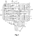
- the transmission illustrated in the figures comprises a solid primary shaft 1 connected directly via a filtration system (damping hub, "damper”, double flywheel or other) 2, to the flywheel 3 of a heat engine (not shown).
- the solid shaft 1 carries a idler gear 4 (idler gear of second R2) which can be connected with it by a first coupling system 5 (C1) such as a dog clutch, synchronizer, or other type of progressive coupler or not ).
- a hollow primary shaft 6 is connected to the rotor of an electric machine 7, preferably (but not necessarily) of the machine type axial discoid type.
- Other types of electric machine can also be used in the context of the invention, for example radial, magnet or excitation coil machines, or reluctance machines.
- the hollow shaft 6 carries two fixed gears 8, 9, first and third.
- the hollow shaft 6 can be connected to the solid primary shaft 1 via the first coupling system 5 (C1).
- a first secondary shaft 10 carries two idler gears 12 (R1) and 11 (R3), of the first and third, and a fixed gear of second 14. It is possible to connect the idler gears 11, 12 to the primary shaft by the intermediary of a second coupling system 13 C2, such as a dog clutch, synchronizer, or other type progressive coupler or not.
- the first secondary shaft 10 also carries a fixed pinion 15 of descent to a differential 16 connected to the wheels (not shown) of the vehicle.
- the solid primary shaft 1 carries a fixed pinion 17 of the fourth, engaged with an idler fourth gear 18 (R4), carried by a second secondary shaft 19.
- the second secondary shaft 19 also carries a third coupling means 21 (C3) of the idler gear of the fourth 18 on the latter.
- the movement of the second secondary shaft 19 is returned by a drive pinion 22 on the differential 16.
- the heat engine can drive an alternator (not shown) capable of meeting the energy requirements of the electric machine by charging a high-voltage traction battery.
- a first assembly then consists in connecting the traction battery to the vehicle's on-board battery by a reversible voltage converter.
- the alternator is a high voltage alternator connectable directly to a battery supplying the electric machine.
- C1 is open (position 1), while C2 is closed so as to secure the idler gear of the first gear 12 with the first secondary shaft 10.
- the transmission is in electric mode on its first gear, called the "city electric” gear.
- the torque supplied by the electric machine to the hollow primary shaft descends through the first fixed pinion R1 on the idler gear 12.
- C2 rotates the pinion 12 and the shaft 10.
- the torque descends from the secondary line on the differential 16 by the drive pinion 16.
- C1 is always open (position 1), while C2 is closed, so as to secure the idler gear of the third R3 with the first secondary shaft 10.
- the transmission is in electric mode on the third gear ratio, called "electric road ”.
- the torque supplied by the electric machine 7 to the hollow primary shaft 6, descends through the fixed gear of third 9 on the idler gear of third R3.
- C1 rotates the pinion R3 and the shaft 10.
- the torque descends from the secondary line on the differential 16 by the pinion 15.
- the transmission is in its fourth gear, in thermal mode.
- C1 is open (position 1). Only C3 is closed.
- the torque supplied by the heat engine passes on the second secondary shaft 19 by the fixed pinions 17 and the idler R4 of the fourth, then descends on the differential by the pinion 22.
- FIGs 8 and 9 illustrate two intermediate hybrid modes known as “long city hybrid 1” and “long city hybrid 2”, obtained from the “short city hybrid” report of the figure 7 .
- the heat engine is synchronized on the second gear before coupling it to the first secondary shaft 10 by the first coupling means C1 in position 2.
- the couples add up.
- FIG 12 illustrates a thermal mode on the second gear, called “long city thermal", where only C1 is closed so as to bring the torque down by R2 on the second gear.
- the transmission described above is of particular interest when it is controlled according to the following two operating sequences known as "week use” and “hybrid use”, depending on whether the user wishes to favor the electric mode for mainly urban or daily driving. , wherever he wishes to further exploit the possibilities of the hybrid mode, to increase his autonomy.
- These modes of use are described below as control methods particularly advantageous, but not limiting, of the transmission described.
- “Weekly use” favors the two electric reports, “city electric” and “electric road” associated with “highway thermal mode” and possibly “highway hybrid mode”.
- the two electric reports are then used by closing C2 on the first or third gear, up to a speed threshold, where we pass on the fourth report in thermal mode, by opening C2 and by coupling the engine to the wheels thanks to C3.
- Hybrid use is enriched by the intermediate thermal ratio (second gear), especially for gear changes under torque. Only one electrical report is used (on the first gear), before passing successively on several hybrid reports, where the first two coupling means C1 and C2 intervene.
- the first hybrid report used when leaving electric mode is the “short city hybrid mode” of the figure 7 .
- hybrid road report of the figure 10 is obtained by coupling the two primary trees on the third gear thanks to C1. As indicated above, switching to hybrid highway mode ( figure 6 ) can be done through the intermediary stage of the “hybrid sport” report of the figure 11 .
- the gear changes between the hybrid reports are made under torque.
- the entire “hybrid use” sequence is carried out without torque breakdown by maintaining traction on each pass, either by the heat engine or by the electric motor. This is the case for ascending and descending passages between “hybrid city short” to “hybrid city long 1 and 2”, “hybrid city long 2”, “hybrid sport” and “hybrid highway”.
Landscapes
- Engineering & Computer Science (AREA)
- Mechanical Engineering (AREA)
- Transportation (AREA)
- Chemical & Material Sciences (AREA)
- Combustion & Propulsion (AREA)
- Automation & Control Theory (AREA)
- General Engineering & Computer Science (AREA)
- Life Sciences & Earth Sciences (AREA)
- Sustainable Development (AREA)
- Sustainable Energy (AREA)
- Power Engineering (AREA)
- Electric Propulsion And Braking For Vehicles (AREA)
- Hybrid Electric Vehicles (AREA)
- Arrangement Of Transmissions (AREA)
Description
- La présente invention se rapporte au domaine des transmissions hybrides pour véhicules automobiles, comportant d'une part un moteur thermique d'entraînement, et d'autre part une machine électrique.
- Plus précisément, elle a pour objet Transmission hybride pour véhicule automobile muni d'un moteur thermique et d'une machine électrique d'entraînement, comportant deux arbres primaires concentriques, dont un arbre primaire plein relié au moteur thermique qui porte un pignon de descente sur un premier arbre secondaire relié aux roues du véhicule par un différentiel, un arbre primaire creux relié à la machine électrique qui porte deux pignons de descente sur le premier arbre secondaire, et un deuxième arbre secondaire renvoyant le mouvement de l'arbre primaire plein sur le différentiel par un pignon d'attaque.
- Les transmissions hybrides ont pour intérêt principal de faire bénéficier la chaîne cinématique d'entraînement d'un véhicule, de deux sources d'énergies, thermique et électrique, dont les apports de couple peuvent se cumuler dans un mode dit hybride, ou être utilisées séparément, soit dans un « mode thermique pur » où la machine électrique ne fournit pas de couple à la chaîne de traction, soit dans un mode « électrique pur », où le moteur thermique ne fournit pas de couple à la chaîne de traction. D'autres fonctionnalités sont également requises, telles que la possibilité de lancer le moteur thermique à l'arrêt ou en roulage, en utilisant la machine électrique comme démarreur, ou celle d'utiliser la machine électrique en générateur de courant, pour charger les batteries.
- Dans sa conception la plus simple, une transmission hybride telle que présentée ci-dessus assure l'ensemble des fonctions requises sur un seul rapport de démultiplication, c'est-à-dire sans la possibilité de bénéficier de plusieurs vitesses de marche avant, comme sur une transmission classique.
- Par la publication
US 2010/0120580 , on connaît une transmission hybride pour véhicule automobile comprenant un arbre primaire plein relié au moteur thermique et un arbre creux relié à la machine électrique. Dans cette architecture, l'arbre primaire creux permet à la machine électrique d'entraîner un ou deux arbres secondaires, auxquels le moteur thermique peut également ajouter son mouvement, grâce à l'intervention de plusieurs coupleurs. - La présente invention vise à réaliser une transmission hybride disposant d'au moins deux rapports distincts en mode électrique, deux rapports distincts en mode thermique, et plusieurs rapports hybrides.
- Dans ce but, elle prévoit :
- un premier moyen de couplage entre les deux arbres primaires pouvant occuper au moins trois positions dans lesquelles :
- le moteur thermique est découplé de la chaîne cinématique reliant la machine électrique aux roues, ou couplé à celle-ci par l'intermédiaire du deuxième arbre secondaire (position 1),
- l'arbre primaire relié au moteur thermique est couplé au premier arbre secondaire pour entraîner les roues avec ou sans l'appoint de la machine électrique (position 2), et
- l'arbre primaire relié au moteur thermique est couplé à l'arbre primaire relié à la machine électrique, de manière à additionner leurs couples respectifs en direction des roues (position 3),
- un deuxième moyen de couplage permettant de coupler l'un ou l'autre des deux pignons de descente de l'arbre primaire creux, sur des pignons fous du premier arbre secondaire, et
- un troisième moyen de couplage permettant de coupler l'arbre primaire plein avec le deuxième arbre secondaire.
- D'autres caractéristiques et avantages de l'invention apparaîtront clairement à la lecture de la description suivante d'un mode de réalisation non limitatif de celle-ci, en se reportant aux dessins annexés, sur lesquels :
- la
figure 1 est un schéma d'architecture de la transmission proposée au point mort, - la
figure 2 correspond au démarrage et au roulage en mode électrique sur un rapport « électrique ville », et en marche arrière, - la
figure 3 correspond au roulage en mode électrique sur un rapport « électrique route », - la
figure 4 correspond au mode de recharge de batterie, - la
figure 5 correspond au roulage en mode thermique sur un rapport « thermique autoroute », - la
figure 6 correspond au roulage en mode hybride sur un premier rapport « hybride autoroute », - la
figure 7 correspond au roulage sur un mode « hybride ville court », - la
figure 8 correspond au roulage sur un rapport « hybride ville long 1 », - la
figure 9 correspond au roulage sur un rapport « hybride ville long 2 », - la
figure 10 correspond au roulage sur un rapport « hybride route », - la
figure 11 correspond au roulage sur un rapport « hybride sport » - la
figure 12 correspond au roulage sur un autre mode thermique dit « thermique ville long ». - La transmission illustrée par les figures comporte un arbre primaire plein 1 connecté directement par l'intermédiaire d'un système de filtration (moyeu amortisseur, « damper », double volant ou autre) 2, au volant d'inertie 3 d'un moteur thermique (non représenté). L'arbre plein 1 porte un pignon fou 4 (pignon fou de deuxième R2) pouvant être connecté avec celui-ci par un premier système de couplage 5 (C1) tel qu'un crabot, synchroniseur, ou autre type de coupleur progressif ou non). Un arbre primaire creux 6 est relié au rotor d'une machine électrique 7, de préférence (mais non obligatoirement) de type machine type axial discoïde. D'autres types de machine électrique sont également utilisables dans le cadre de l'invention, par exemple des machines radiales, à aimant ou à bobine d'excitation, ou des machines à réluctance. L'arbre creux 6 porte deux pignons fixes 8, 9, de première et de troisième. L'arbre creux 6 peut être relié à l'arbre primaire plein 1 par intermédiaire du premier système de couplage 5 (C1). Un premier arbre secondaire 10 porte deux pignons fous 12(R1) et 11(R3), de première et de troisième, et un pignon fixe de deuxième 14. On peut relier les pignons fous 11, 12 à l'arbre primaire par l'intermédiaire d'un deuxième système de couplage 13 C2, tel qu'un crabot, synchroniseur, ou autre type de coupleur progressif ou non. Le premier arbre secondaire 10 porte également un pignon fixe 15 de descente vers un différentiel 16 relié aux roues (non représentées) du véhicule.
- A son extrémité gauche sur le schéma, l'arbre primaire plein 1 porte un pignon fixe 17 de quatrième, en prise avec un pignon fou de quatrième 18 (R4), porté par un deuxième arbre secondaire 19. Le deuxième arbre secondaire 19 porte également un troisième moyen de couplage 21 (C3) du pignon fou de quatrième 18 sur celui-ci. Le mouvement du deuxième arbre secondaire 19 est renvoyé par un pignon d'attaque 22 sur le différentiel 16.
- Le premier moyen de couplage C1 peut occuper au moins trois positions dans lesquelles :
- le moteur thermique est découplé de la chaîne cinématique reliant la machine électrique 7 aux roues, ou couplé à celle-ci par l'intermédiaire du deuxième arbre secondaire (position 1), sur les
figures 1 ,2 ,3 ,5 ,11 , - l'arbre primaire relié au moteur thermique est couplé au premier arbre secondaire pour entraîner les roues avec ou sans l'appoint de la machine électrique (position 2), sur les
figures 8, 9 ,12 , et - l'arbre primaire relié au moteur thermique est couplé à l'arbre primaire relié à la machine électrique, de manière à additionner leurs couples respectifs en direction des roues (position 3), sur les
figures 4 ,6 ,7 ,10 . - Par ailleurs, le moteur thermique peut entraîner un alternateur (non représenté) capable d'assurer les besoins énergétiques de la machine électrique en chargeant une batterie de traction haute tension. Un premier montage consiste alors à relier la batterie de traction à la batterie de bord du véhicule par un convertisseur de tension réversible. Une autre solution est que l'alternateur soit un alternateur haute tension connectable directement à une batterie d'alimentation de la machine électrique. Avec ces dispositions, le moteur thermique et l'alternateur de recharge de la batterie de bord peuvent constituer un groupe électrogène à faible coût, capable d'assurer les besoins énergétiques de la machine électrique de traction en mode électrique.
- Sur la
figure 1 , les trois moyens de couplage C1, C2, C3, sont ouverts. - Sur la
figure 2 , C1 est ouvert (position 1), tandis que C2 est fermé de manière à solidariser le pignon fou du premier rapport 12 avec le premier arbre secondaire 10. La transmission est en mode électrique sur son premier rapport, dit rapport « électrique ville ». Le couple fourni par la machine électrique à l'arbre primaire creux descend par le premier pignon fixe R1 sur le pignon fou 12. C2 lie en rotation le pignon 12 et l'arbre 10. Le couple descend de la ligne secondaire sur le différentiel 16 par le pignon d'attaque 16. - Sur la
figure 3 , C1 est toujours ouvert (position 1), tandis que C2 est fermé, de manière à solidariser le pignon fou de troisième R3 avec le premier arbre secondaire 10. La transmission est en mode électrique sur le troisième rapport de la transmission, dit « électrique route ». Le couple fourni par la machine électrique 7 à l'arbre primaire creux 6, descend par le pignon fixe de troisième 9 sur le pignon fou de troisième R3. C1 lie en rotation le pignon R3 et l'arbre 10. Le couple descend de la ligne secondaire sur le différentiel 16 par le pignon 15. - Sur la
figure 4 , on est en mode de recharge de batterie. Seul C1 5 est fermé, en position 3. Les deux arbres primaires 1, 6 sont solidaires et le moteur thermique entraîne la machine électrique, fonctionnant alors en générateur. - Sur la
figure 5 , la transmission est sur son quatrième rapport, en mode thermique. Sur ce rapport dit rapport « thermique autoroute », C1 est ouvert (position 1). Seul C3 est fermé. Le couple fourni par le moteur thermique passe sur le deuxième arbre secondaire 19 par les pignons fixe 17 et fou R4 de quatrième, puis redescend sur le différentiel par le pignon 22. - A partir de cette situation, on peut passer en mode hybride en rajoutant au moteur thermique l'appoint de la machine électrique, grâce à la fermeture de C1 en position 3. Le quatrième rapport devient alors un rapport « hybride autoroute », illustré par la
figure 6 . - Sur la
figure 7 , on est en mode hybride sur le premier rapport de la transmission, qui devient dans ce cas un rapport « hybride ville court ». C1 est fermé en position 3, de manière à solidariser les deux arbres primaires 1, 6 ; C2 est fermé sur le premier rapport (pignons R1, 12). Les couples du moteur thermique et de la machine électrique sont donc additionnés sur le premier rapport. - Les
figures 8 et 9 illustrent deux modes hybrides intermédiaires dits « hybride ville long 1 » et « hybride ville long 2 », obtenus à partir du rapport « hybride ville court » de lafigure 7 . En maintenant le premier rapport engagé sur la machine électrique, on synchronise le moteur thermique sur le deuxième rapport avant de le coupler à au premier arbre secondaire 10 par le premier moyen de couplage C1 en position 2. Comme indiqué sur lafigure 8 , les couples s'additionnent. - Sans dégager C1, on peut dégager C2, puis synchroniser la machine électrique avec le premier arbre secondaire 10, avant d'engager C2 pour les rendre solidaires. Toujours sur le deuxième rapport de la transmission, on est ainsi passé sur le rapport « hybride ville long 2 » de la
figure 9 . - En basculant C1 en position 3 à partir de la
figure 9 après synchronisation à vide du moteur thermique, on passe sur le troisième rapport dans la situation de lafigure 10 dite « hybride route », avec addition des couples thermique et électrique. - On peut ensuite passer sur le quatrième rapport en mode hybride pour rejoindre la
figure 11 , en laissant la machine électrique maintenir la transmission sur le troisième rapport pendant le passage. Pour cela, on dégage C1 couplage (retour en position 1), puis on ferme C3, après avoir synchronisé à vide le moteur thermique. - A partir de la
figure 10 , si on ouvre C1, pour fermer C3 tout en maintenant C2 fermé, on peut rejoindre un rapport « hybride sport» illustré par lafigure 11 , à partir duquel on peut repasser sur le rapport « hybride autoroute » de lafigure 6 . - Enfin la
figure 12 illustre un mode thermique sur le deuxième rapport, dit « thermique ville long », où seul C1 est fermé de manière à faire descendre le couple par R2 sur le rapport de deuxième. - En résumé, les trois positions du premier moyen de couplage 5 et l'intervention combinée du deuxième moyen de couplage 13 et du troisième moyen de couplage assurent à la transmission au moins les modes suivants :
- un mode électrique sur les deux premiers rapports de la transmission, dits « électrique ville » et « électrique court » (cf.
figures 2 et 3 ), - un mode thermique sur le deuxième et le quatrième rapport, dits respectivement « thermique ville long et » et « thermique autoroute » (cf.
figures 12 et5 ), - un mode hybride sur le premier rapport, dit « hybride ville court » (cf.
figure 7 ) - deux modes hybrides sur le deuxième rapport, dits « hybride ville 1 » et « hybride ville 2 » (
figures 8 et 9 ), - un mode hybride sur le troisième rapport, dit « hybride route » (cf.
figure 10 ) et sur le quatrième rapport dit « hybride autoroute » (figure 6 ) et « hybride sport » (figure 11 ), et - un mode de recharge de batterie (cf.
figure 4 ). - La transmission décrite ci-dessus trouve un intérêt particulier lorsqu'elle est commandée selon les deux séquences de fonctionnement suivantes dites « utilisation semaine » et « utilisation hybride », selon que l'utilisateur souhaite privilégier le mode électrique pour une conduite principalement urbaine ou journalière, où qu'il souhaite exploiter davantage les possibilités du mode hybride, pour augmenter son autonomie. Ces modes d'utilisation sont décrits ci-dessous comme des procédés de commande particulièrement avantageux, mais non limitatifs, de la transmission décrite.
- L'« utilisation semaine » privilégie les deux rapports électriques, « électrique ville » et « électrique route » associés au « mode thermique autoroute » et éventuellement au mode « hybride autoroute ». Les deux rapports électriques sont alors utilisés en fermant C2 sur le pignon de première ou de troisième, jusqu'à un seuil de vitesse, où on passe sur le quatrième rapport en mode thermique, en ouvrant C2 et en couplant le moteur thermique aux roues grâce à C3. Sur le quatrième rapport, on peut aussi disposer en plus du rapport hybride en couplant le moteur thermique aux roues en fermant C3, tout en couplant les deux arbres primaires grâce à C2.
- L'« utilisation hybride » est enrichie par le rapport thermique intermédiaire (deuxième rapport), notamment pour les changements de rapport sous couple. On utilise seulement un seul rapport électrique (sur le pignon de première), avant de passer successivement sur plusieurs rapports hybrides, où les deux premiers moyens de couplages C1 et C2 interviennent. Le premier rapport hybride utilisé en quittant le mode électrique est le « mode hybride ville court » de la
figure 7 . On peut ensuite passer au premier « rapport hybrides ville long » (hybride ville long 1) de lafigure 8 au deuxième (figure 9 ) avec la même position de fermeture de C2, en couplant l'arbre primaire creux avec le premier arbre secondaire. Si on dégage C1, on peut bénéficier des deux rapports « hybride ville long » 1 et 2, selon que C2 engage R1 ou R3. Le « rapport hybride route » de lafigure 10 est obtenu en couplant les deux arbres primaires sur le troisième rapport grâce à C1. Comme indiqué plus haut, le passage sur le mode hybride autoroute (figure 6 ) peut s'effectuer en passant par l'étape intermédiaire du rapport « hybride sport » de lafigure 11 . - Conformément à l'invention, les passages de vitesses entre les rapports hybrides s'effectuent sous couple. En particulier, l'ensemble de la séquence « utilisation hybride » s'effectue sans rupture de couple en maintenant la traction sur chaque passage, soit par le moteur thermique, soit par le moteur électrique. C'est le cas pour les passages montants et descendants entre « hybride ville court » à « hybride ville long 1 et 2 », « hybride ville long 2 », « hybride sport » et « hybride autoroute ».
Claims (11)
- Transmission hybride pour véhicule automobile muni d'un moteur thermique et d'une machine électrique d'entraînement (7), comportant deux arbres primaires (1, 6) concentriques, dont un arbre primaire plein (1) relié au moteur thermique qui porte un pignon de descente (4) sur un premier arbre secondaire (10) relié aux roues du véhicule par un différentiel (16), un arbre primaire creux (6) relié à la machine électrique qui porte deux pignons de descente (8, 9) sur le premier arbre secondaire (10), et un deuxième arbre secondaire (19) renvoyant le mouvement de l'arbre primaire plein (1) sur le différentiel (16) par un pignon d'attaque (22), caractérisée en ce qu'elle présente- un premier moyen de couplage (C1) entre les deux arbres primaires (1, 6) pouvant occuper au moins trois positions dans lesquelles :• le moteur thermique est découplé de la chaîne cinématique reliant la machine électrique (7) aux roues, ou couplé à celle-ci par l'intermédiaire du deuxième arbre secondaire (position 1),• l'arbre primaire relié au moteur thermique (1) est couplé au premier arbre secondaire (10) pour entraîner les roues avec ou sans l'appoint de la machine électrique (position 2), et• l'arbre primaire relié au moteur thermique (1) est couplé à l'arbre primaire relié à la machine électrique (6), de manière à additionner leurs couples respectifs en direction des roues (position 3),- un deuxième moyen de couplage (C2) permettant de coupler l'un ou l'autre des deux pignons de descente (8, 9) de l'arbre primaire creux (6), sur des pignons fous (12, 11) du premier arbre secondaire (10), et- un troisième moyen de couplage (C3) permettant de coupler l'arbre primaire plein (1) avec le deuxième arbre secondaire (19).
- Transmission hybride selon la revendication 1, caractérisée en ce que les trois positions du premier moyen de couplage (C1) et l'intervention combinée du deuxième (C2) et du troisième (C3) moyen de couplage, lui assurent au moins :- un mode électrique sur deux rapports,- un mode thermique sur un deuxième et sur un quatrième rapport,- un mode hybride sur trois rapports.
- Transmission hybride selon l'une des revendications précédentes, caractérisée en ce que le moteur thermique entraîne un alternateur capable d'assurer les besoins énergétiques de la machine électrique en chargeant une batterie de traction haute tension.
- Transmission hybride selon la revendication 3, caractérisée en ce que la batterie de traction est reliée à une batterie de bord du véhicule par un convertisseur de tension réversible
- Transmission hybride selon la revendication 3, caractérisée en ce que l'alternateur est un alternateur haute tension connectable directement à une batterie d'alimentation de la machine électrique.
- Procédé de commande d'une transmission hybride conforme à l'une des revendications 1 à 5, caractérisé en ce qu'on utilise la machine électrique (7) comme seule source d'énergie motrice sur deux rapports électriques en fermant le deuxième moyen de couplage (C2), jusqu'à un seuil de vitesse, au delà duquel on passe sur un rapport thermique en ouvrant le deuxième moyen de couplage (C2) et en couplant le moteur thermique aux roues par le troisième moyen de couplage (C3) .
- Procédé de commande selon la revendication 6, caractérisé en ce qu'on dispose en plus d'un rapport hybride en couplant les deux arbres primaires par le deuxième moyen de couplage (C2) tout en maintenant couplés le moteur thermique aux roues par fermeture du troisième moyen de couplage (C3).
- Procédé de commande d'une transmission hybride conforme à l'une des revendications 1 à 5, caractérisé en ce qu'on utilise seulement un seul rapport électrique, avant de passer successivement sur plusieurs rapports hybrides, où les deux premiers moyens de couplages (C1, C2) sont fermés.
- Procédé de commande selon la revendication 8, caractérisé en ce qu'on peut obtenir deux rapports hybrides avec la même position de fermeture du deuxième moyen de couplage (C2), selon que les deux arbres primaires sont couplés ou que l'arbre primaire creux est couplé avec le premier arbre secondaire.
- Procédé de commande selon la revendication 8 ou 9, caractérisé en ce qu'on peut obtenir deux rapports hybrides distincts avec la même position de fermeture du premier moyen de couplage (C1) selon que le deuxième moyen de couplage (C2) couple l'un ou l'autre des deux pignons de descente de l'arbre primaire creux sur le premier arbre secondaire, avec celui-ci.
- Procédé de commande selon la revendication 8 ou 9, caractérisé en ce que les passages de vitesses entre les rapports hybrides s'effectuent sans rupture de couple en maintenant la traction sur chaque passage, soit par le moteur thermique, soit par le moteur électrique.
Applications Claiming Priority (2)
| Application Number | Priority Date | Filing Date | Title |
|---|---|---|---|
| FR1159675A FR2981611B1 (fr) | 2011-10-25 | 2011-10-25 | Transmission hybride trois arbres pour vehicule automobile et procede de commande |
| PCT/FR2012/052084 WO2013060955A1 (fr) | 2011-10-25 | 2012-09-18 | Transmission hybride trois arbres pour vehicule automobile et procede de commande |
Publications (2)
| Publication Number | Publication Date |
|---|---|
| EP2771199A1 EP2771199A1 (fr) | 2014-09-03 |
| EP2771199B1 true EP2771199B1 (fr) | 2020-01-01 |
Family
ID=47022989
Family Applications (1)
| Application Number | Title | Priority Date | Filing Date |
|---|---|---|---|
| EP12773055.4A Active EP2771199B1 (fr) | 2011-10-25 | 2012-09-18 | Transmission hybride trois arbres pour vehicule automobile et procede de commande |
Country Status (8)
| Country | Link |
|---|---|
| US (1) | US9381905B2 (fr) |
| EP (1) | EP2771199B1 (fr) |
| JP (1) | JP6301837B2 (fr) |
| KR (1) | KR101982655B1 (fr) |
| CN (1) | CN103958247B (fr) |
| FR (1) | FR2981611B1 (fr) |
| RU (1) | RU2592179C2 (fr) |
| WO (1) | WO2013060955A1 (fr) |
Families Citing this family (12)
| Publication number | Priority date | Publication date | Assignee | Title |
|---|---|---|---|---|
| FR2973299B1 (fr) * | 2011-04-01 | 2013-08-16 | Renault Sa | Transmission hybride pour vehicule automobile et procede de commande |
| DE102012016990A1 (de) * | 2012-07-02 | 2014-01-02 | Volkswagen Aktiengesellschaft | Hybridantriebsstrang für ein Kraftfahrzeug, Hybridfahrzeug und Verwendung desselben |
| FR3007696B1 (fr) * | 2013-06-26 | 2015-06-26 | Renault Sa | Transmission hybride avec une machine electrique additionnelle et procede de commande |
| FR3018107B1 (fr) * | 2014-02-28 | 2017-07-14 | Renault Sas | Transmission automatique pour vehicule automobile a propulsion thermique ou hybride |
| FR3022495B1 (fr) * | 2014-06-24 | 2017-12-22 | Renault Sas | Transmission hybride a machine electrique deportee et procede de commande de changements de rapports |
| FR3032393B1 (fr) * | 2015-02-06 | 2018-05-04 | Renault S.A.S. | Transmission hybride pour vehicule automobile et procede de transmission du couple d'une machine electrique de traction |
| US10414263B2 (en) * | 2016-04-08 | 2019-09-17 | Hyundai Motor Company | Transmission for vehicle |
| DE102016108124A1 (de) | 2016-05-02 | 2017-11-02 | Getrag Getriebe- Und Zahnradfabrik Hermann Hagenmeyer Gmbh & Cie Kg | Hybridantriebsstrang |
| RU2653106C1 (ru) * | 2016-11-29 | 2018-05-07 | Федеральное государственное бюджетное образовательное учреждение высшего образования "Тюменский индустриальный университет" (ТИУ) | Гибридная трансмиссия с простым планетарным механизмом |
| RU2730094C1 (ru) * | 2019-10-07 | 2020-08-17 | Хадеев Равиль Гфиевич | Трансмиссия для гибридного транспорта |
| DE102021200138A1 (de) | 2021-01-11 | 2022-07-14 | Zf Friedrichshafen Ag | Getriebeanordnung, Hybrid-Getriebeanordnung, Hybrid-Antriebsstrang sowie Kraftfahrzeug |
| DE102021200144A1 (de) | 2021-01-11 | 2022-07-14 | Zf Friedrichshafen Ag | Getriebeanordnung, Hybrid-Getriebeanordnung, Hybrid-Antriebsstrang sowie Kraftfahrzeug |
Family Cites Families (19)
| Publication number | Priority date | Publication date | Assignee | Title |
|---|---|---|---|---|
| JP2857535B2 (ja) | 1992-05-19 | 1999-02-17 | 株式会社エクォス・リサーチ | ハイブリッド型車両 |
| FR2805325B1 (fr) * | 2000-02-23 | 2002-06-07 | Peugeot Citroen Automobiles Sa | Systeme de transmission de mouvement pour vehicule a propulsion hybride |
| FR2811395B1 (fr) * | 2000-07-06 | 2002-12-06 | Peugeot Citroen Automobiles Sa | Boite de vitesses pour vehicule hybride |
| US7082850B2 (en) * | 2003-12-30 | 2006-08-01 | Eaton Corporation | Hybrid powertrain system |
| JP4312767B2 (ja) * | 2006-02-13 | 2009-08-12 | 株式会社日本製鋼所 | 押出機用駆動装置 |
| DE102007014150A1 (de) * | 2007-03-23 | 2008-09-25 | EGS Entwicklungsgesellschaft für Getriebesysteme mbH | Lastschaltbares Mehrstufengetriebe |
| WO2009140229A2 (fr) * | 2008-05-16 | 2009-11-19 | Borgwarner Inc. | Transmission manuelle utilisant une chaîne et un train épicycloïdal en tant qu'entraînement final |
| JP4572956B2 (ja) * | 2008-06-03 | 2010-11-04 | トヨタ自動車株式会社 | 車両の駆動装置 |
| US8120290B2 (en) * | 2008-10-13 | 2012-02-21 | General Electric Company | Energy management system to improve efficiency of electric and hybrid drive trains |
| US8523734B2 (en) * | 2008-11-07 | 2013-09-03 | Ricardo, Inc. | Multi-mode hybrid transmission |
| JP2010162923A (ja) * | 2009-01-13 | 2010-07-29 | Honda Motor Co Ltd | ハイブリッド車両の動力伝達装置 |
| JP4607222B2 (ja) * | 2009-01-27 | 2011-01-05 | 本田技研工業株式会社 | ハイブリッド車両 |
| US8226512B2 (en) * | 2009-03-25 | 2012-07-24 | GM Global Technology Operations LLC | 8-speed hybrid transmission |
| US8100801B2 (en) * | 2009-03-25 | 2012-01-24 | GM Global Technology Operations LLC | 8-speed hybrid transmission |
| JP2011112130A (ja) * | 2009-11-26 | 2011-06-09 | Aisin Ai Co Ltd | 動力伝達装置 |
| US8241173B2 (en) * | 2010-01-12 | 2012-08-14 | GM Global Technology Operations LLC | Single motor hybrid transmission |
| US8657712B2 (en) * | 2010-09-15 | 2014-02-25 | Chrysler Group Llc | Multi-speed drive unit |
| US8444516B2 (en) * | 2010-09-15 | 2013-05-21 | Chrysler Group Llc | Multi-speed drive unit |
| FR2973299B1 (fr) | 2011-04-01 | 2013-08-16 | Renault Sa | Transmission hybride pour vehicule automobile et procede de commande |
-
2011
- 2011-10-25 FR FR1159675A patent/FR2981611B1/fr not_active Expired - Fee Related
-
2012
- 2012-09-18 CN CN201280057341.1A patent/CN103958247B/zh active Active
- 2012-09-18 US US14/354,435 patent/US9381905B2/en not_active Expired - Fee Related
- 2012-09-18 KR KR1020147013984A patent/KR101982655B1/ko active Active
- 2012-09-18 JP JP2014537682A patent/JP6301837B2/ja active Active
- 2012-09-18 WO PCT/FR2012/052084 patent/WO2013060955A1/fr not_active Ceased
- 2012-09-18 RU RU2014121078/11A patent/RU2592179C2/ru active
- 2012-09-18 EP EP12773055.4A patent/EP2771199B1/fr active Active
Non-Patent Citations (1)
| Title |
|---|
| None * |
Also Published As
| Publication number | Publication date |
|---|---|
| JP6301837B2 (ja) | 2018-03-28 |
| FR2981611B1 (fr) | 2014-02-28 |
| EP2771199A1 (fr) | 2014-09-03 |
| JP2015502502A (ja) | 2015-01-22 |
| KR101982655B1 (ko) | 2019-05-27 |
| WO2013060955A1 (fr) | 2013-05-02 |
| US20140315681A1 (en) | 2014-10-23 |
| RU2014121078A (ru) | 2015-12-10 |
| FR2981611A1 (fr) | 2013-04-26 |
| KR20140085550A (ko) | 2014-07-07 |
| CN103958247A (zh) | 2014-07-30 |
| CN103958247B (zh) | 2017-10-24 |
| RU2592179C2 (ru) | 2016-07-20 |
| US9381905B2 (en) | 2016-07-05 |
Similar Documents
| Publication | Publication Date | Title |
|---|---|---|
| EP2771199B1 (fr) | Transmission hybride trois arbres pour vehicule automobile et procede de commande | |
| EP2694309B1 (fr) | Transmission hybride pour vehicule automobile et procede de commande | |
| EP3160786B1 (fr) | Transmission hybride a machine électrique déportée et procédé de commande de changements de rapports | |
| EP3013618B1 (fr) | Transmission hybride avec une machine electrique additionnelle | |
| EP2726757B1 (fr) | Architecture électrique de véhicule hybride, véhicule hybride et procédé de commande | |
| CN102166943A (zh) | 具体用于机动车辆的驱动系统以及用于运行此类驱动系统的方法 | |
| JP6542779B2 (ja) | ハイブリッド推進及び関連する制御技術を有する自動車用変速装置 | |
| EP3055159B1 (fr) | Groupe motopropulseur pour véhicule automobile et procédé de fonctionnement | |
| WO2013117463A1 (fr) | Transmission hybride pour vehicule automobile avec entrainement du compresseur de climatisation | |
| EP3297863B1 (fr) | Transmission hybride a double couplage d'arbres et procédé de commande de changements de rapports | |
| EP3253633B1 (fr) | Transmission hybride pour vehicule automobile et procede de transmission du couple d'une machine electrique de traction | |
| FR3001187A3 (fr) | Transmission hybride pour vehicule automobile a arbres primaires concentriques et procede de commande |
Legal Events
| Date | Code | Title | Description |
|---|---|---|---|
| PUAI | Public reference made under article 153(3) epc to a published international application that has entered the european phase |
Free format text: ORIGINAL CODE: 0009012 |
|
| 17P | Request for examination filed |
Effective date: 20140331 |
|
| AK | Designated contracting states |
Kind code of ref document: A1 Designated state(s): AL AT BE BG CH CY CZ DE DK EE ES FI FR GB GR HR HU IE IS IT LI LT LU LV MC MK MT NL NO PL PT RO RS SE SI SK SM TR |
|
| DAX | Request for extension of the european patent (deleted) | ||
| STAA | Information on the status of an ep patent application or granted ep patent |
Free format text: STATUS: EXAMINATION IS IN PROGRESS |
|
| 17Q | First examination report despatched |
Effective date: 20180206 |
|
| RIC1 | Information provided on ipc code assigned before grant |
Ipc: F16H 3/00 20060101ALI20130514BHEP Ipc: B60K 6/48 20071001AFI20130514BHEP Ipc: F16H 3/093 20060101ALI20130514BHEP Ipc: B60W 10/113 20120101ALI20130514BHEP Ipc: B60W 20/00 20160101ALI20130514BHEP |
|
| GRAP | Despatch of communication of intention to grant a patent |
Free format text: ORIGINAL CODE: EPIDOSNIGR1 |
|
| STAA | Information on the status of an ep patent application or granted ep patent |
Free format text: STATUS: GRANT OF PATENT IS INTENDED |
|
| INTG | Intention to grant announced |
Effective date: 20190724 |
|
| GRAS | Grant fee paid |
Free format text: ORIGINAL CODE: EPIDOSNIGR3 |
|
| GRAA | (expected) grant |
Free format text: ORIGINAL CODE: 0009210 |
|
| STAA | Information on the status of an ep patent application or granted ep patent |
Free format text: STATUS: THE PATENT HAS BEEN GRANTED |
|
| AK | Designated contracting states |
Kind code of ref document: B1 Designated state(s): AL AT BE BG CH CY CZ DE DK EE ES FI FR GB GR HR HU IE IS IT LI LT LU LV MC MK MT NL NO PL PT RO RS SE SI SK SM TR |
|
| REG | Reference to a national code |
Ref country code: GB Ref legal event code: FG4D Free format text: NOT ENGLISH |
|
| REG | Reference to a national code |
Ref country code: CH Ref legal event code: EP Ref country code: AT Ref legal event code: REF Ref document number: 1219356 Country of ref document: AT Kind code of ref document: T Effective date: 20200115 |
|
| REG | Reference to a national code |
Ref country code: DE Ref legal event code: R096 Ref document number: 602012066922 Country of ref document: DE |
|
| REG | Reference to a national code |
Ref country code: IE Ref legal event code: FG4D Free format text: LANGUAGE OF EP DOCUMENT: FRENCH |
|
| REG | Reference to a national code |
Ref country code: NL Ref legal event code: MP Effective date: 20200101 |
|
| REG | Reference to a national code |
Ref country code: LT Ref legal event code: MG4D |
|
| PG25 | Lapsed in a contracting state [announced via postgrant information from national office to epo] |
Ref country code: FI Free format text: LAPSE BECAUSE OF FAILURE TO SUBMIT A TRANSLATION OF THE DESCRIPTION OR TO PAY THE FEE WITHIN THE PRESCRIBED TIME-LIMIT Effective date: 20200101 Ref country code: PT Free format text: LAPSE BECAUSE OF FAILURE TO SUBMIT A TRANSLATION OF THE DESCRIPTION OR TO PAY THE FEE WITHIN THE PRESCRIBED TIME-LIMIT Effective date: 20200527 Ref country code: CZ Free format text: LAPSE BECAUSE OF FAILURE TO SUBMIT A TRANSLATION OF THE DESCRIPTION OR TO PAY THE FEE WITHIN THE PRESCRIBED TIME-LIMIT Effective date: 20200101 Ref country code: NO Free format text: LAPSE BECAUSE OF FAILURE TO SUBMIT A TRANSLATION OF THE DESCRIPTION OR TO PAY THE FEE WITHIN THE PRESCRIBED TIME-LIMIT Effective date: 20200401 Ref country code: LT Free format text: LAPSE BECAUSE OF FAILURE TO SUBMIT A TRANSLATION OF THE DESCRIPTION OR TO PAY THE FEE WITHIN THE PRESCRIBED TIME-LIMIT Effective date: 20200101 Ref country code: NL Free format text: LAPSE BECAUSE OF FAILURE TO SUBMIT A TRANSLATION OF THE DESCRIPTION OR TO PAY THE FEE WITHIN THE PRESCRIBED TIME-LIMIT Effective date: 20200101 Ref country code: RS Free format text: LAPSE BECAUSE OF FAILURE TO SUBMIT A TRANSLATION OF THE DESCRIPTION OR TO PAY THE FEE WITHIN THE PRESCRIBED TIME-LIMIT Effective date: 20200101 |
|
| PG25 | Lapsed in a contracting state [announced via postgrant information from national office to epo] |
Ref country code: GR Free format text: LAPSE BECAUSE OF FAILURE TO SUBMIT A TRANSLATION OF THE DESCRIPTION OR TO PAY THE FEE WITHIN THE PRESCRIBED TIME-LIMIT Effective date: 20200402 Ref country code: IS Free format text: LAPSE BECAUSE OF FAILURE TO SUBMIT A TRANSLATION OF THE DESCRIPTION OR TO PAY THE FEE WITHIN THE PRESCRIBED TIME-LIMIT Effective date: 20200501 Ref country code: HR Free format text: LAPSE BECAUSE OF FAILURE TO SUBMIT A TRANSLATION OF THE DESCRIPTION OR TO PAY THE FEE WITHIN THE PRESCRIBED TIME-LIMIT Effective date: 20200101 Ref country code: LV Free format text: LAPSE BECAUSE OF FAILURE TO SUBMIT A TRANSLATION OF THE DESCRIPTION OR TO PAY THE FEE WITHIN THE PRESCRIBED TIME-LIMIT Effective date: 20200101 Ref country code: SE Free format text: LAPSE BECAUSE OF FAILURE TO SUBMIT A TRANSLATION OF THE DESCRIPTION OR TO PAY THE FEE WITHIN THE PRESCRIBED TIME-LIMIT Effective date: 20200101 Ref country code: BG Free format text: LAPSE BECAUSE OF FAILURE TO SUBMIT A TRANSLATION OF THE DESCRIPTION OR TO PAY THE FEE WITHIN THE PRESCRIBED TIME-LIMIT Effective date: 20200401 |
|
| REG | Reference to a national code |
Ref country code: DE Ref legal event code: R097 Ref document number: 602012066922 Country of ref document: DE |
|
| PG25 | Lapsed in a contracting state [announced via postgrant information from national office to epo] |
Ref country code: ES Free format text: LAPSE BECAUSE OF FAILURE TO SUBMIT A TRANSLATION OF THE DESCRIPTION OR TO PAY THE FEE WITHIN THE PRESCRIBED TIME-LIMIT Effective date: 20200101 Ref country code: RO Free format text: LAPSE BECAUSE OF FAILURE TO SUBMIT A TRANSLATION OF THE DESCRIPTION OR TO PAY THE FEE WITHIN THE PRESCRIBED TIME-LIMIT Effective date: 20200101 Ref country code: EE Free format text: LAPSE BECAUSE OF FAILURE TO SUBMIT A TRANSLATION OF THE DESCRIPTION OR TO PAY THE FEE WITHIN THE PRESCRIBED TIME-LIMIT Effective date: 20200101 Ref country code: SM Free format text: LAPSE BECAUSE OF FAILURE TO SUBMIT A TRANSLATION OF THE DESCRIPTION OR TO PAY THE FEE WITHIN THE PRESCRIBED TIME-LIMIT Effective date: 20200101 Ref country code: DK Free format text: LAPSE BECAUSE OF FAILURE TO SUBMIT A TRANSLATION OF THE DESCRIPTION OR TO PAY THE FEE WITHIN THE PRESCRIBED TIME-LIMIT Effective date: 20200101 Ref country code: SK Free format text: LAPSE BECAUSE OF FAILURE TO SUBMIT A TRANSLATION OF THE DESCRIPTION OR TO PAY THE FEE WITHIN THE PRESCRIBED TIME-LIMIT Effective date: 20200101 |
|
| PLBE | No opposition filed within time limit |
Free format text: ORIGINAL CODE: 0009261 |
|
| STAA | Information on the status of an ep patent application or granted ep patent |
Free format text: STATUS: NO OPPOSITION FILED WITHIN TIME LIMIT |
|
| REG | Reference to a national code |
Ref country code: AT Ref legal event code: MK05 Ref document number: 1219356 Country of ref document: AT Kind code of ref document: T Effective date: 20200101 |
|
| 26N | No opposition filed |
Effective date: 20201002 |
|
| PG25 | Lapsed in a contracting state [announced via postgrant information from national office to epo] |
Ref country code: AT Free format text: LAPSE BECAUSE OF FAILURE TO SUBMIT A TRANSLATION OF THE DESCRIPTION OR TO PAY THE FEE WITHIN THE PRESCRIBED TIME-LIMIT Effective date: 20200101 Ref country code: IT Free format text: LAPSE BECAUSE OF FAILURE TO SUBMIT A TRANSLATION OF THE DESCRIPTION OR TO PAY THE FEE WITHIN THE PRESCRIBED TIME-LIMIT Effective date: 20200101 |
|
| PG25 | Lapsed in a contracting state [announced via postgrant information from national office to epo] |
Ref country code: PL Free format text: LAPSE BECAUSE OF FAILURE TO SUBMIT A TRANSLATION OF THE DESCRIPTION OR TO PAY THE FEE WITHIN THE PRESCRIBED TIME-LIMIT Effective date: 20200101 Ref country code: SI Free format text: LAPSE BECAUSE OF FAILURE TO SUBMIT A TRANSLATION OF THE DESCRIPTION OR TO PAY THE FEE WITHIN THE PRESCRIBED TIME-LIMIT Effective date: 20200101 |
|
| PG25 | Lapsed in a contracting state [announced via postgrant information from national office to epo] |
Ref country code: MC Free format text: LAPSE BECAUSE OF FAILURE TO SUBMIT A TRANSLATION OF THE DESCRIPTION OR TO PAY THE FEE WITHIN THE PRESCRIBED TIME-LIMIT Effective date: 20200101 |
|
| REG | Reference to a national code |
Ref country code: CH Ref legal event code: PL |
|
| REG | Reference to a national code |
Ref country code: BE Ref legal event code: MM Effective date: 20200930 |
|
| PG25 | Lapsed in a contracting state [announced via postgrant information from national office to epo] |
Ref country code: LU Free format text: LAPSE BECAUSE OF NON-PAYMENT OF DUE FEES Effective date: 20200918 |
|
| PG25 | Lapsed in a contracting state [announced via postgrant information from national office to epo] |
Ref country code: LI Free format text: LAPSE BECAUSE OF NON-PAYMENT OF DUE FEES Effective date: 20200930 Ref country code: IE Free format text: LAPSE BECAUSE OF NON-PAYMENT OF DUE FEES Effective date: 20200918 Ref country code: CH Free format text: LAPSE BECAUSE OF NON-PAYMENT OF DUE FEES Effective date: 20200930 Ref country code: BE Free format text: LAPSE BECAUSE OF NON-PAYMENT OF DUE FEES Effective date: 20200930 |
|
| PG25 | Lapsed in a contracting state [announced via postgrant information from national office to epo] |
Ref country code: TR Free format text: LAPSE BECAUSE OF FAILURE TO SUBMIT A TRANSLATION OF THE DESCRIPTION OR TO PAY THE FEE WITHIN THE PRESCRIBED TIME-LIMIT Effective date: 20200101 Ref country code: MT Free format text: LAPSE BECAUSE OF FAILURE TO SUBMIT A TRANSLATION OF THE DESCRIPTION OR TO PAY THE FEE WITHIN THE PRESCRIBED TIME-LIMIT Effective date: 20200101 Ref country code: CY Free format text: LAPSE BECAUSE OF FAILURE TO SUBMIT A TRANSLATION OF THE DESCRIPTION OR TO PAY THE FEE WITHIN THE PRESCRIBED TIME-LIMIT Effective date: 20200101 |
|
| PG25 | Lapsed in a contracting state [announced via postgrant information from national office to epo] |
Ref country code: MK Free format text: LAPSE BECAUSE OF FAILURE TO SUBMIT A TRANSLATION OF THE DESCRIPTION OR TO PAY THE FEE WITHIN THE PRESCRIBED TIME-LIMIT Effective date: 20200101 Ref country code: AL Free format text: LAPSE BECAUSE OF FAILURE TO SUBMIT A TRANSLATION OF THE DESCRIPTION OR TO PAY THE FEE WITHIN THE PRESCRIBED TIME-LIMIT Effective date: 20200101 |
|
| P01 | Opt-out of the competence of the unified patent court (upc) registered |
Effective date: 20230608 |
|
| REG | Reference to a national code |
Ref country code: GB Ref legal event code: 732E Free format text: REGISTERED BETWEEN 20231228 AND 20240103 |
|
| REG | Reference to a national code |
Ref country code: DE Ref legal event code: R081 Ref document number: 602012066922 Country of ref document: DE Owner name: NEW H POWERTRAIN HOLDING, S.L.U., ES Free format text: FORMER OWNER: RENAULT S.A.S., BOULOGNE-BILLANCOURT, FR |
|
| PGFP | Annual fee paid to national office [announced via postgrant information from national office to epo] |
Ref country code: DE Payment date: 20250919 Year of fee payment: 14 |
|
| PGFP | Annual fee paid to national office [announced via postgrant information from national office to epo] |
Ref country code: GB Payment date: 20250918 Year of fee payment: 14 |
|
| PGFP | Annual fee paid to national office [announced via postgrant information from national office to epo] |
Ref country code: FR Payment date: 20250922 Year of fee payment: 14 |