EP2771264B1 - Vorrichtung zur übertragung von objekten zwischen maschinen zur intermittierenden bewegung dieser objekte und maschinen zur kontinuierlichen bewegung der objekte sowie entsprechende verpackungsvorrichtung - Google Patents
Vorrichtung zur übertragung von objekten zwischen maschinen zur intermittierenden bewegung dieser objekte und maschinen zur kontinuierlichen bewegung der objekte sowie entsprechende verpackungsvorrichtung Download PDFInfo
- Publication number
- EP2771264B1 EP2771264B1 EP12779058.2A EP12779058A EP2771264B1 EP 2771264 B1 EP2771264 B1 EP 2771264B1 EP 12779058 A EP12779058 A EP 12779058A EP 2771264 B1 EP2771264 B1 EP 2771264B1
- Authority
- EP
- European Patent Office
- Prior art keywords
- conveyor
- machine
- handling members
- segment
- articles
- Prior art date
- Legal status (The legal status is an assumption and is not a legal conclusion. Google has not performed a legal analysis and makes no representation as to the accuracy of the status listed.)
- Not-in-force
Links
- 238000004806 packaging method and process Methods 0.000 title claims description 5
- 238000009434 installation Methods 0.000 claims description 25
- 239000000945 filler Substances 0.000 claims 4
- 125000006850 spacer group Chemical group 0.000 claims 1
- 238000007664 blowing Methods 0.000 description 9
- 238000006073 displacement reaction Methods 0.000 description 3
- 238000010438 heat treatment Methods 0.000 description 2
- 230000000694 effects Effects 0.000 description 1
- 238000002347 injection Methods 0.000 description 1
- 239000007924 injection Substances 0.000 description 1
- 238000012432 intermediate storage Methods 0.000 description 1
- 238000012423 maintenance Methods 0.000 description 1
- 238000000034 method Methods 0.000 description 1
- 210000000056 organ Anatomy 0.000 description 1
- 238000005096 rolling process Methods 0.000 description 1
- 238000003860 storage Methods 0.000 description 1
- 238000004804 winding Methods 0.000 description 1
Images




Classifications
-
- B—PERFORMING OPERATIONS; TRANSPORTING
- B65—CONVEYING; PACKING; STORING; HANDLING THIN OR FILAMENTARY MATERIAL
- B65B—MACHINES, APPARATUS OR DEVICES FOR, OR METHODS OF, PACKAGING ARTICLES OR MATERIALS; UNPACKING
- B65B43/00—Forming, feeding, opening or setting-up containers or receptacles in association with packaging
- B65B43/42—Feeding or positioning bags, boxes, or cartons in the distended, opened, or set-up state; Feeding preformed rigid containers, e.g. tins, capsules, glass tubes, glasses, to the packaging position; Locating containers or receptacles at the filling position; Supporting containers or receptacles during the filling operation
- B65B43/46—Feeding or positioning bags, boxes, or cartons in the distended, opened, or set-up state; Feeding preformed rigid containers, e.g. tins, capsules, glass tubes, glasses, to the packaging position; Locating containers or receptacles at the filling position; Supporting containers or receptacles during the filling operation using grippers
-
- B—PERFORMING OPERATIONS; TRANSPORTING
- B65—CONVEYING; PACKING; STORING; HANDLING THIN OR FILAMENTARY MATERIAL
- B65G—TRANSPORT OR STORAGE DEVICES, e.g. CONVEYORS FOR LOADING OR TIPPING, SHOP CONVEYOR SYSTEMS OR PNEUMATIC TUBE CONVEYORS
- B65G47/00—Article or material-handling devices associated with conveyors; Methods employing such devices
- B65G47/22—Devices influencing the relative position or the attitude of articles during transit by conveyors
- B65G47/24—Devices influencing the relative position or the attitude of articles during transit by conveyors orientating the articles
-
- B—PERFORMING OPERATIONS; TRANSPORTING
- B65—CONVEYING; PACKING; STORING; HANDLING THIN OR FILAMENTARY MATERIAL
- B65G—TRANSPORT OR STORAGE DEVICES, e.g. CONVEYORS FOR LOADING OR TIPPING, SHOP CONVEYOR SYSTEMS OR PNEUMATIC TUBE CONVEYORS
- B65G47/00—Article or material-handling devices associated with conveyors; Methods employing such devices
- B65G47/22—Devices influencing the relative position or the attitude of articles during transit by conveyors
- B65G47/26—Devices influencing the relative position or the attitude of articles during transit by conveyors arranging the articles, e.g. varying spacing between individual articles
- B65G47/30—Devices influencing the relative position or the attitude of articles during transit by conveyors arranging the articles, e.g. varying spacing between individual articles during transit by a series of conveyors
- B65G47/31—Devices influencing the relative position or the attitude of articles during transit by conveyors arranging the articles, e.g. varying spacing between individual articles during transit by a series of conveyors by varying the relative speeds of the conveyors forming the series
-
- B—PERFORMING OPERATIONS; TRANSPORTING
- B65—CONVEYING; PACKING; STORING; HANDLING THIN OR FILAMENTARY MATERIAL
- B65G—TRANSPORT OR STORAGE DEVICES, e.g. CONVEYORS FOR LOADING OR TIPPING, SHOP CONVEYOR SYSTEMS OR PNEUMATIC TUBE CONVEYORS
- B65G47/00—Article or material-handling devices associated with conveyors; Methods employing such devices
- B65G47/74—Feeding, transfer, or discharging devices of particular kinds or types
- B65G47/84—Star-shaped wheels or devices having endless travelling belts or chains, the wheels or devices being equipped with article-engaging elements
- B65G47/841—Devices having endless travelling belts or chains equipped with article-engaging elements
-
- B—PERFORMING OPERATIONS; TRANSPORTING
- B65—CONVEYING; PACKING; STORING; HANDLING THIN OR FILAMENTARY MATERIAL
- B65G—TRANSPORT OR STORAGE DEVICES, e.g. CONVEYORS FOR LOADING OR TIPPING, SHOP CONVEYOR SYSTEMS OR PNEUMATIC TUBE CONVEYORS
- B65G2201/00—Indexing codes relating to handling devices, e.g. conveyors, characterised by the type of product or load being conveyed or handled
- B65G2201/02—Articles
- B65G2201/0235—Containers
- B65G2201/0244—Bottles
- B65G2201/0247—Suspended bottles
-
- B—PERFORMING OPERATIONS; TRANSPORTING
- B65—CONVEYING; PACKING; STORING; HANDLING THIN OR FILAMENTARY MATERIAL
- B65G—TRANSPORT OR STORAGE DEVICES, e.g. CONVEYORS FOR LOADING OR TIPPING, SHOP CONVEYOR SYSTEMS OR PNEUMATIC TUBE CONVEYORS
- B65G47/00—Article or material-handling devices associated with conveyors; Methods employing such devices
- B65G47/52—Devices for transferring articles or materials between conveyors i.e. discharging or feeding devices
- B65G47/68—Devices for transferring articles or materials between conveyors i.e. discharging or feeding devices adapted to receive articles arriving in one layer from one conveyor lane and to transfer them in individual layers to more than one conveyor lane or to one broader conveyor lane, or vice versa, e.g. combining the flows of articles conveyed by more than one conveyor
- B65G47/71—Devices for transferring articles or materials between conveyors i.e. discharging or feeding devices adapted to receive articles arriving in one layer from one conveyor lane and to transfer them in individual layers to more than one conveyor lane or to one broader conveyor lane, or vice versa, e.g. combining the flows of articles conveyed by more than one conveyor the articles being discharged or distributed to several distinct separate conveyors or to a broader conveyor lane
Definitions
- the present invention relates to the transfer of articles, and in particular containers, between machines implementing movements of articles in different movements and steps.
- the invention is more particularly applicable to product packaging installations in containers, comprising a container blowing machine and a machine for filling and capping the containers.
- the intermittent blowing machine generally comprises an inlet conveyor conveying preforms produced by injection, a furnace for heating these preforms, blowing nozzles mounted facing molds for injecting air into the heated preforms received in the molds, and an exit conveyor for evacuating the containers.
- the molds are fed simultaneously into preforms so that several containers can be blown simultaneously before being evacuated.
- the output conveyor is for example formed of a comb animated with an intermittent rectilinear movement of the pilgrim type to evacuate the containers in batches corresponding to the number of simultaneously blown containers.
- the continuous-motion filling and capping machine generally comprises a container transport device which is provided with container grippers and which passes under filling nozzles and then under corking pins of said containers. containers.
- the device comprises a flexible conveyor extending around at least two pulleys to have at least one rectilinear section opposite a conveyor of the first machine and a rounded section facing a conveyor of the second machine, the conveyor flexible of the device bearing lateral projecting bodies of the articles fixed at regular intervals so that the support members have a pitch corresponding to the first step in said straight section and said rounded section has a radius such that the support members have a pitch corresponding to the second step in the rounded section.
- the curvature of the flexible conveyor in the rounded section causes an increase in the spacing of the free ends of the load-bearing members relative to each other and therefore an increase in not with respect to the step of the support members in the rectilinear section.
- the passage of articles from one section to another therefore entails an adjustment of these.
- the device according to the invention comprises at least one guide rail to which the articles are suspended, the guide rail extending along the rectilinear section and along at least part of the rounded section and the support members. are arranged to be movable between an active position to make contact with the items and a retracted inactive position in which the articles are out of contact with the support members.
- the invention also relates to a packaging installation comprising a container blowing machine with an intermittent rectilinear displacement output conveyor according to a first predetermined step, a machine for filling the containers with a continuous rotary displacement input conveyor, and a transfer device of the above type installed between the blowing machine and the filling machine in such a way that the rectilinear section extends opposite the outlet conveyor of the blowing machine and the rounded section is tangent to the conveyor inlet of the filling machine, the device comprising a driving pulley controlled by the filling machine.
- the installation according to the invention which is described here is a container packaging installation comprising a body surmounted by a projecting neck which extends a flange.
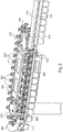
- the installation according to the invention comprises a machine 100 for blowing containers, a machine 200 for filling the containers and a transfer device 300.
- the machine 100 comprises an input conveyor injecting molded preforms, a preform heating furnace, blowing nozzles mounted opposite the molds for injecting air into the preforms received in the molds, and an exit conveyor for evacuating the containers.
- the molds are here arranged in a line and are simultaneously fed into containers so that several containers can be blown simultaneously before being evacuated.
- the machine 100 comprises an output conveyor 110 here formed of a comb animated with an intermittent rectilinear movement of the type with a mit step along a rectangular trajectory represented in double dashed line on the figure 1 .
- the comb is provided with as many container receiving cells as the machine 100 counts molds.
- the output conveyor 110 can thus evacuate the containers in batches corresponding to the number of simultaneously blown containers.
- the machine 100 is known per se, so that only the part directly interacting with the transfer device of the invention is represented here, namely the output conveyor 110.
- the intermittent linear displacement output conveyor 110 operates according to a first predetermined step.
- the machine 200 comprises an inlet conveyor 210, here a rotating platform, which is provided with grippers of the containers arranged vertically above the filling nozzles of the containers.
- the machine 200 is known per se, so that only the part directly interacting with the transfer device of the invention is represented here, namely the input conveyor 210.
- the input conveyor 210 operates according to a movement continuously rotating at a second predetermined pitch.
- the transfer device 300 comprises a flexible conveyor 310 extending around two pulleys 320, 330 to have two rectilinear sections 311, 313, between the pulleys 320, 330, and two rounded sections 312, 314 respectively around the pulley 320 and the pulley 330.
- transfer member 300 is arranged in such a way that the rectilinear section 311 extends tangentially to an end portion of the conveyor 110 of the first machine 100 and the rounded portion 312 extends tangentially to a portion of the conveyor 310 of the second machine 300.
- the pulley 320 is a driving pulley driven by the machine 200 so that the rectilinear section 311 of the flexible conveyor 310 is stretched.
- the transfer device 300 comprises a means, generally 340, for guiding and tensioning the flexible conveyor 310.
- the guiding and tensioning means comprise a fixed shoe 341 providing support for the rectilinear section 311 and a movable shoe 342 providing support. to the rectilinear section 313. Between the two pads 341, 342 are mounted resilient bracing means here constituted by springs 343 providing tension maintenance of the flexible conveyor 310.
- Two guide rails 350 extend parallel to each other from the machine 100 to the machine 200 along the rectilinear section 311 and a portion of the rounded section 312.
- the guide rails 350 are separated by a space having a width between the diameter of the neck of the containers and the diameter of the collar thereof so that the containers can be suspended from the guide rails 350 by their flange.
- the flexible conveyor 310 carries, in lateral projection, support members 360 of the containers.
- the support members 360 are fixed at regular intervals so that the organs 360 have a pitch corresponding to the first step in the rectilinear section 311.
- the pulley 320, and therefore the rounded section 312, have a radius such that the support members 360 have a pitch corresponding to the second step in the rounded section 312.
- the flexible conveyor 310 is here a chain having links on each of which is mounted one of the support members 360.
- Each guide member 360 is mounted on the flexible conveyor 310 to be movable between an active position in which the support member 360 extends in the vicinity of the guide rails 350 to push the containers along the guide rails 350 and a retracted inactive position in which the containers supported by the guide rails 350 escape contact with the support members 360.
- the transfer device comprises control means 360 of the support members arranged to bring the support members 360 in the active position in a transfer zone T straddling a portion of the rectilinear section 311 and a portion adjacent rounded section 312 and inactive position outside this area.
- each support member 360 is mounted on the corresponding link of the flexible conveyor 310 to pivot about a horizontal axis parallel to a local direction of movement of the flexible conveyor 310 of such so that in the active position the support member 360 has a finger lowered to be engaged in the neck of a container and inactive position the finger of the support device 360 is raised to be clear of the neck of the container .
- the control means here comprise a cam 370 secured to the conveyor 110 of the first machine 100 and arranged to hold the support members 360 in their inactive position when the conveyor 110 is engaged with the containers and to let the gripping members in charge 360 return to their active position under the effect of the elastic return means when the conveyor 110 is clear containers.
- the elastic return means connect each support member 360 and the link on which it is mounted.
- the front ramp 371 of the cam 370 which extends forward of the cells of the comb forming the conveyor 110, encounters rollers 380 integral with the gripping members 360 and brings the gripping members 360 into the inactive position.
- the advancements of the flexible conveyor 310 and that of the conveyor 110 are determined in such a way that in second position the conveyor 110 brings containers in the immediate vicinity of the containers already loaded on the flexible conveyor 310 in such a way that between two successive batches of containers loaded on the flexible conveyor, there is no support member 360 free.
- the conveyor 110 is then moved back ( figure 4 ) to be clear of the containers.
- the cam 370 releases the rollers 380 and the gripping members in charge return to the active position under the action of the elastic return means.
- the conveyor 110 is then returned to its first position to be brought into engagement with newly blown containers.
- the flexible conveyor 310 continues its movement and brings facing the conveyor 210 containers which are loaded progressively into the gripping members of the conveyor 210.
- a cam 390 winding facing a portion of the rounded section 312 cooperates with the rollers 380 to gradually bring the support members 360 into their inactive position ensuring the transfer of the containers of the flexible conveyor 310 to the conveyor 210.
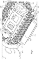
- the support members 360 are mounted on the flexible conveyor to move laterally relative to the flexible conveyor.
- the support members 360 are mounted on the links of the flexible conveyor 310 to pivot about an axis of articulation perpendicular to the rails 350.
- Each support member 360 has a lever shape having a connected end to the axis of articulation and an opposite end arranged to bear on the side of the neck, here above the collar.
- the lever is also provided with a roller 380 to bear on the cam 370 secured to the conveyor 110.
- the operation is identical to that of the first embodiment except that the support members 360 pivot between their active position ( figure 7 ) and their inactive position ( figure 6 ) according to a trajectory in a horizontal arc of a circle and no longer a vertical one.
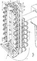
- each support member 360 is mounted to slide vertically relative to the flexible conveyor 310 between its active position and its inactive position.
- the control means here comprise a cam path 400 extending opposite the flexible conveyor and the support members 360 are associated with a roller 410 rolling on the cam path 400.
- the transfer device according to the invention can be used in any type of article processing installation, between two machines operating at different stages of advancement.
- the support members may have a different structure and be formed for example of clamps.
- the flexible conveyor may be formed of a deformable strip.
- the conveyor of the first machine is an input conveyor and the conveyor of the second machine is an output conveyor or vice versa.
- the driving pulley supports the rounded section of the flexible conveyor of the transfer device.
- the control means may have a structure different from that described.
- the control means of the support members may be arranged to bring the support members in active position in a transfer area of the articles extending astride at least a portion of the section rectilinear 311 and at least one adjacent portion of the rounded section 312 and inactive position outside this area at least at both ends thereof, or alternatively in one or more other areas than those mentioned above.
Landscapes
- Engineering & Computer Science (AREA)
- Mechanical Engineering (AREA)
- Specific Conveyance Elements (AREA)
- Auxiliary Devices For And Details Of Packaging Control (AREA)
- Processing Of Meat And Fish (AREA)
- Framework For Endless Conveyors (AREA)
Claims (13)
- Vorrichtung (300) zur Übertragung von Gegenständen zwischen einer ersten Maschine (100), die mit einer intermittierenden Bewegung der Gegenstände gemäß einem ersten vorgegebenen Schritt arbeitet, und einer zweiten Maschine (200), die mit einer kontinuierlichen Bewegung der Gegenstände gemäß einem zweiten vorgegebenen Schritt arbeitet, wobei die Vorrichtung einen flexiblen Förderer (310) umfasst, der sich um mindestens zwei Rollen (320, 330) erstreckt, um mindestens einen geradlinigen Abschnitt (311) gegenüber einem Förderer der ersten Maschine und einen abgerundeten Abschnitt (312) gegenüber einem Förderer der zweiten Maschine zu haben, wobei der flexible Förderer der Vorrichtung seitlich vorstehende, in regelmäßigen Abständen befestigte Übernahmeelemente (360) zur Übernahme von Gegenständen trägt, derart, dass die Übernahmeelemente einen Schritt haben, der dem ersten Schritt in dem genannten geradlinigen Abschnitt entspricht, und der genannte abgerundete Abschnitt einen Radius hat, so dass die Übernahmeelemente einen Schritt haben, der dem zweiten Schritt in dem abgerundeten Abschnitt entspricht, dadurch gekennzeichnet, dass die Vorrichtung mindestens eine Führungsschiene (350) umfasst, an der die Gegenstände aufgehängt sind, wobei sich die Führungsschiene entlang des geradlinigen Abschnittes (311) und entlang mindestens eines Teils des abgerundeten Abschnittes (312) erstreckt, und dass die Übernahmeelemente (360) so ausgebildet sind, dass sie zwischen einer aktiven Position nahe der Führungsschiene (350) zur Kontaktaufnahme mit den Gegenständen und einer ausgerückten inaktiven Position beweglich sind, in der die Gegenstände außer Kontakt mit den Übernahmeelementen treten, wobei die Vorrichtung Steuermittel zum Steuern der Übernahmeelemente umfasst, die so ausgebildet sind, dass sie die Übernahmeelemente in die aktive Position in einer Übergabezone zur Übergabe der Gegenstände bringen, die sich über mindestens einen Teil des geradlinigen Abschnittes (311) und mindestens einen angrenzenden Teil des abgerundeten Abschnittes (312) erstreckt, sowie in eine inaktive Position außerhalb dieser Zone, zumindest an beiden Enden dieser Zone.
- Vorrichtung nach Anspruch 1, bei der der Förderer (110) der ersten Maschine ein Einlassförderer und der Förderer (210) der zweiten Maschine ein Auslassförderer ist.
- Vorrichtung nach Anspruch 1, bei der die Übernahmeelemente (360) so ausgebildet sind, dass sie die Gegenstände die Führungsschiene entlang schieben.
- Vorrichtung nach Anspruch 1, bei der die Übernahmeelemente in Bezug auf den flexiblen Förderer (310) vertikal verschiebbar gelagert sind.
- Vorrichtung nach Anspruch 4, bei der die Steuermittel eine Nockenbahn umfassen, die sich gegenüber dem flexiblen Förderer (310) erstreckt, und die Übernahmeelemente (360) mit einer Rolle verbunden sind, die auf der Nockenbahn rollt.
- Vorrichtung nach Anspruch 1, bei der die Übernahmeelemente (360) auf dem flexiblen Förderer (310) angebracht sind, um sich seitlich in Bezug auf den flexiblen Förderer zu verschieben.
- Vorrichtung nach Anspruch 1, bei der die Übernahmeelemente (360) auf dem flexiblen Förderer (310) angebracht sind, um sich um eine horizontale Achse zu verschwenken, die parallel zu einer lokalen Bewegungsrichtung des flexiblen Förderers ist.
- Vorrichtung nach Anspruch 6 oder Anspruch 7, bei der die Steuermittel eine Nockenbahn (370) umfassen, die fest mit dem Förderer (110) der ersten Maschine (100) verbunden und so ausgebildet ist, dass sie die Übernahmeelemente (360) in ihrer inaktiven Position hält, wenn der Förderer in Eingriff mit den Gegenständen steht.
- Vorrichtung nach Anspruch 8, bei der der Förderer (110) der ersten Maschine ein Kamm mit hin- und hergehender geradliniger Bewegung ist.
- Vorrichtung nach Anspruch 1, bei der der flexible Förderer (310) eine Kette ist, die Glieder hat, an denen jeweils eines der Übernahmeelemente (360) angebracht ist.
- Vorrichtung nach Anspruch 10, umfassend ein Element (340) zum Führen und Spannen der Kette, das zwei Kufen umfasst, die zwischen zwei geradlinigen Abschnitten (311, 313) der Kette angebracht sind, um an diesen zur Anlage zu kommen, wobei die beiden Kufen über elastische Abstandshaltemittel verbunden sind.
- Verpackungsanlage, umfassend eine Behälterblasmaschine (100) mit einem Auslassförderer mit intermittierender geradliniger Bewegung gemäß einem ersten vorgegebenen Schritt und eine Behälterabfüllmaschine (200) mit einem Einlassförderer mit kontinuierlicher Drehbewegung, dadurch gekennzeichnet, das die Anlage eine Übergabevorrichtung (300) gemäß einem der vorhergehenden Ansprüche umfasst, die zwischen der Blasmaschine und der Abfüllmaschine derart installiert ist, dass sich der geradlinige Abschnitt (311) gegenüber dem Auslassförderer der Blasmaschine erstreckt und der abgerundete Abschnitt (213) tangential zum Einlassförderer der Abfüllmaschine ist, und dass die Vorrichtung eine Antriebsrolle (320) umfasst, die von der Abfüllmaschine gesteuert wird.
- Anlage nach Anspruch 12, bei der die Antriebsrolle (320) den abgerundeten Abschnitt (312) des flexiblen Förderers (310) der Übergabevorrichtung (300) trägt.
Applications Claiming Priority (2)
| Application Number | Priority Date | Filing Date | Title |
|---|---|---|---|
| FR1159736A FR2981920B1 (fr) | 2011-10-26 | 2011-10-26 | Dispositif de transfert d'articles entre des machines a deplacement intermittent et a deplacement continu des articles et installation de conditionnement correspondante |
| PCT/EP2012/071312 WO2013060875A1 (fr) | 2011-10-26 | 2012-10-26 | Dispositif de transfert d'articles entre des machines a deplacement intermittent et a deplacement continu des articles et installation de conditionnement correspondante |
Publications (2)
| Publication Number | Publication Date |
|---|---|
| EP2771264A1 EP2771264A1 (de) | 2014-09-03 |
| EP2771264B1 true EP2771264B1 (de) | 2017-07-12 |
Family
ID=47088879
Family Applications (1)
| Application Number | Title | Priority Date | Filing Date |
|---|---|---|---|
| EP12779058.2A Not-in-force EP2771264B1 (de) | 2011-10-26 | 2012-10-26 | Vorrichtung zur übertragung von objekten zwischen maschinen zur intermittierenden bewegung dieser objekte und maschinen zur kontinuierlichen bewegung der objekte sowie entsprechende verpackungsvorrichtung |
Country Status (6)
| Country | Link |
|---|---|
| US (1) | US8813948B2 (de) |
| EP (1) | EP2771264B1 (de) |
| BR (1) | BR112014007417A2 (de) |
| ES (1) | ES2640277T3 (de) |
| FR (1) | FR2981920B1 (de) |
| WO (1) | WO2013060875A1 (de) |
Cited By (1)
| Publication number | Priority date | Publication date | Assignee | Title |
|---|---|---|---|---|
| CN110255096A (zh) * | 2019-05-24 | 2019-09-20 | 苏州德睿联自动化科技有限公司 | 汇流条移载系统 |
Families Citing this family (6)
| Publication number | Priority date | Publication date | Assignee | Title |
|---|---|---|---|---|
| DE102013100627A1 (de) * | 2013-01-22 | 2014-07-24 | Krones Aktiengesellschaft | Verfahren zum betreiben einer behälterbehandlungsanlage und behälterbehandlungsanlage |
| FR3004982B1 (fr) * | 2013-04-24 | 2015-05-01 | Serac Group | Dispositif de maintien d'un recipient comprenant une lame ressort et installation de traitement de recipients comprenant un tel dispositif |
| US9994401B2 (en) * | 2014-06-11 | 2018-06-12 | Tetra Laval Holdings & Finance S.A. | Transfer arrangement |
| JP7442440B2 (ja) * | 2017-09-15 | 2024-03-04 | テトラ ラバル ホールディングス アンド ファイナンス エス エイ | チェーン駆動ジョーシステム用の張力調整装置 |
| CN109745231A (zh) * | 2019-02-27 | 2019-05-14 | 四川制药制剂有限公司 | 一种制备帕瑞昔布冻干粉针剂的系统 |
| MX2023012531A (es) | 2021-04-27 | 2023-10-31 | Hershey Co | Sistema y metodo para transportar moldes de confiteria. |
Family Cites Families (11)
| Publication number | Priority date | Publication date | Assignee | Title |
|---|---|---|---|---|
| GB441681A (en) * | 1934-06-20 | 1936-01-20 | United Glass Bottle Manufactue | Improvements in or relating to lehr stacking or feeding mechanisms |
| US3330400A (en) * | 1966-03-08 | 1967-07-11 | Miehle Goss Dexter Inc | Mechanism for transferring cylindrical articles |
| DE2702395A1 (de) * | 1977-01-21 | 1978-08-03 | Orthmann & Herbst | Transportvorrichtung fuer auf einer unterlage im abstand durch mitnehmer gefoerderte behaelter |
| FR2691401B1 (fr) * | 1992-05-20 | 1994-08-05 | Sidel Sa | Unite pour le traitement thermique de recipients en pet lors de la fabrication de ceux-ci. |
| FR2691956B1 (fr) * | 1992-06-05 | 1994-08-26 | Sidel Sa | Dispositif de chargement de récipients sur un élément de transport. |
| DE19542647C2 (de) * | 1995-11-15 | 1998-03-19 | Alfill Engineering Gmbh & Co K | Vorrichtung zur Teilungsänderung bei Getränkebehältern |
| IT1285693B1 (it) * | 1996-05-08 | 1998-06-18 | Azionaria Costruzioni Acma Spa | Metodo e dispositivo per l'alimentazione ordinaria di prodotti ricevuti alla rinfusa |
| US6889485B2 (en) * | 2002-02-09 | 2005-05-10 | Meadwestvaco Packaging Systems, Llc | Article grouping mechanism |
| JP4017898B2 (ja) * | 2002-03-18 | 2007-12-05 | 東洋自動機株式会社 | スパウト又はスパウト付き袋の搬送装置 |
| ITTO20050832A1 (it) * | 2005-11-24 | 2007-05-25 | Opm S P A | Convogliatore ad anello per il trasferimento di prodotti, in particolare prodotti alimentari |
| DK2483181T3 (da) * | 2009-09-29 | 2014-08-25 | Sluis Cigar Machinery Bv | Behandling af reumatoid artritis med en kombination af laquinimod og methotrexat |
-
2011
- 2011-10-26 FR FR1159736A patent/FR2981920B1/fr not_active Expired - Fee Related
-
2012
- 2012-10-26 BR BR112014007417A patent/BR112014007417A2/pt not_active IP Right Cessation
- 2012-10-26 WO PCT/EP2012/071312 patent/WO2013060875A1/fr not_active Ceased
- 2012-10-26 US US13/661,926 patent/US8813948B2/en not_active Expired - Fee Related
- 2012-10-26 EP EP12779058.2A patent/EP2771264B1/de not_active Not-in-force
- 2012-10-26 ES ES12779058.2T patent/ES2640277T3/es active Active
Cited By (1)
| Publication number | Priority date | Publication date | Assignee | Title |
|---|---|---|---|---|
| CN110255096A (zh) * | 2019-05-24 | 2019-09-20 | 苏州德睿联自动化科技有限公司 | 汇流条移载系统 |
Also Published As
| Publication number | Publication date |
|---|---|
| EP2771264A1 (de) | 2014-09-03 |
| BR112014007417A2 (pt) | 2017-04-04 |
| ES2640277T3 (es) | 2017-11-02 |
| WO2013060875A1 (fr) | 2013-05-02 |
| US8813948B2 (en) | 2014-08-26 |
| FR2981920B1 (fr) | 2015-08-07 |
| FR2981920A1 (fr) | 2013-05-03 |
| US20130139928A1 (en) | 2013-06-06 |
Similar Documents
| Publication | Publication Date | Title |
|---|---|---|
| EP2771264A1 (de) | Vorrichtung zur übertragung von objekten zwischen maschinen zur intermittierenden bewegung dieser objekte und maschinen zur kontinuierlichen bewegung der objekte sowie entsprechende verpackungsvorrichtung | |
| EP1973821B1 (de) | Weichenvorrichtung für behälter | |
| EP4234448B1 (de) | Bürstengliederband zum transport von vorformlingen | |
| EP0267120A1 (de) | Positionieren von Glasscheiben, um diese zu biegen | |
| CN111216390A (zh) | 后端部夹持器、输送胎面的输送器和方法 | |
| FR2490202A1 (fr) | Appareil pour extraire d'une ligne de transport des articles plats et flexibles, notamment des articles imprimes, entraines a l'aide d'un transporteur | |
| EP1989115B1 (de) | Vorrichtung zum füllen eines behälters | |
| EP2885230B1 (de) | Anlage zur behandlung von artikeln mit einer transferschraubenvorrichtung | |
| EP2051918B1 (de) | Vorrichtung zum umdrehen von behältern | |
| EP2490965B1 (de) | Vorrichtung zur herstellung von produktchargen zu ihrer abfüllung in behältnisse | |
| EP0617691B1 (de) | Verfahren und vorrichtung zum bewegen von gegenständen um eine bahn und verwendung der vorrichtung | |
| FR2657852A1 (fr) | Dispositif de transport pour plaques a surface sensible, notamment pour plaquettes a circuit imprime a revetement humide. | |
| WO2007025908A1 (fr) | Dispositif de chargement de recipients sur un element de transport comportant des moyens d'ejection des recipients mal charges | |
| FR2780961A1 (fr) | Dispositifs de chargement et dechargement pour machine d'impression | |
| FR2891264A1 (fr) | Mecanisme d'evacuation destine a une machine d'inspection de verre de type distributeur en etoile | |
| EP1506086A1 (de) | Speicher- und transfer-vorrichtung von bandförmigen produkten zur verwendung in der reifenherstellung | |
| EP0568417A1 (de) | Handhabungsanlage zum Fördern von Blechen von einer Schere zu einer Stapelvorrichtung | |
| FR3102761A1 (fr) | Circuit d'accumulation de préformes alignées et redressées | |
| FR3101622A1 (fr) | Convoyeur à accumulation de préformes présentant un trajet en arc de cercle | |
| EP3856482B1 (de) | Vorrichtung zur herstellung von hohlkörpern mit einem element zur steuerung der strömung von hohlkörpern, die von einem elektrischen linearmotor angetrieben werden | |
| EP3546194A1 (de) | Fördervorrichtung, die mit einem sicherheitssystem ausgestattet ist | |
| FR2653690A1 (fr) | Appareil pour former automatiquement une extremite pointue sur un tube brut destine a etre etire. | |
| EP0637546B1 (de) | Vorrichtung zum Anbringen von hülsenförmigen Etiketten auf Verpackungen oder ähnlichen Gegenständen | |
| FR3093091A1 (fr) | Accumulateur en U pour transfert de petits objets notamment alimentaires | |
| EP0165127B1 (de) | Automatische Ausstoss- und Evakuierungsanlage für verschiedene Reihen von Behältern und mit solcher Anlage versehene Verpackungsmaschine |
Legal Events
| Date | Code | Title | Description |
|---|---|---|---|
| PUAI | Public reference made under article 153(3) epc to a published international application that has entered the european phase |
Free format text: ORIGINAL CODE: 0009012 |
|
| 17P | Request for examination filed |
Effective date: 20140318 |
|
| AK | Designated contracting states |
Kind code of ref document: A1 Designated state(s): AL AT BE BG CH CY CZ DE DK EE ES FI FR GB GR HR HU IE IS IT LI LT LU LV MC MK MT NL NO PL PT RO RS SE SI SK SM TR |
|
| DAX | Request for extension of the european patent (deleted) | ||
| 17Q | First examination report despatched |
Effective date: 20160126 |
|
| GRAP | Despatch of communication of intention to grant a patent |
Free format text: ORIGINAL CODE: EPIDOSNIGR1 |
|
| STAA | Information on the status of an ep patent application or granted ep patent |
Free format text: STATUS: GRANT OF PATENT IS INTENDED |
|
| INTG | Intention to grant announced |
Effective date: 20161219 |
|
| GRAS | Grant fee paid |
Free format text: ORIGINAL CODE: EPIDOSNIGR3 |
|
| RIN1 | Information on inventor provided before grant (corrected) |
Inventor name: BRUNEE, JACKY |
|
| GRAA | (expected) grant |
Free format text: ORIGINAL CODE: 0009210 |
|
| STAA | Information on the status of an ep patent application or granted ep patent |
Free format text: STATUS: THE PATENT HAS BEEN GRANTED |
|
| RAP1 | Party data changed (applicant data changed or rights of an application transferred) |
Owner name: SERAC GROUP |
|
| AK | Designated contracting states |
Kind code of ref document: B1 Designated state(s): AL AT BE BG CH CY CZ DE DK EE ES FI FR GB GR HR HU IE IS IT LI LT LU LV MC MK MT NL NO PL PT RO RS SE SI SK SM TR |
|
| REG | Reference to a national code |
Ref country code: GB Ref legal event code: FG4D Free format text: NOT ENGLISH |
|
| RIN1 | Information on inventor provided before grant (corrected) |
Inventor name: BRUNEE, JACKY |
|
| REG | Reference to a national code |
Ref country code: CH Ref legal event code: EP |
|
| REG | Reference to a national code |
Ref country code: AT Ref legal event code: REF Ref document number: 908112 Country of ref document: AT Kind code of ref document: T Effective date: 20170715 |
|
| REG | Reference to a national code |
Ref country code: IE Ref legal event code: FG4D Free format text: LANGUAGE OF EP DOCUMENT: FRENCH |
|
| REG | Reference to a national code |
Ref country code: DE Ref legal event code: R096 Ref document number: 602012034480 Country of ref document: DE |
|
| REG | Reference to a national code |
Ref country code: NL Ref legal event code: FP |
|
| REG | Reference to a national code |
Ref country code: ES Ref legal event code: FG2A Ref document number: 2640277 Country of ref document: ES Kind code of ref document: T3 Effective date: 20171102 |
|
| REG | Reference to a national code |
Ref country code: LT Ref legal event code: MG4D |
|
| REG | Reference to a national code |
Ref country code: AT Ref legal event code: MK05 Ref document number: 908112 Country of ref document: AT Kind code of ref document: T Effective date: 20170712 |
|
| PG25 | Lapsed in a contracting state [announced via postgrant information from national office to epo] |
Ref country code: HR Free format text: LAPSE BECAUSE OF FAILURE TO SUBMIT A TRANSLATION OF THE DESCRIPTION OR TO PAY THE FEE WITHIN THE PRESCRIBED TIME-LIMIT Effective date: 20170712 Ref country code: LT Free format text: LAPSE BECAUSE OF FAILURE TO SUBMIT A TRANSLATION OF THE DESCRIPTION OR TO PAY THE FEE WITHIN THE PRESCRIBED TIME-LIMIT Effective date: 20170712 Ref country code: FI Free format text: LAPSE BECAUSE OF FAILURE TO SUBMIT A TRANSLATION OF THE DESCRIPTION OR TO PAY THE FEE WITHIN THE PRESCRIBED TIME-LIMIT Effective date: 20170712 Ref country code: SE Free format text: LAPSE BECAUSE OF FAILURE TO SUBMIT A TRANSLATION OF THE DESCRIPTION OR TO PAY THE FEE WITHIN THE PRESCRIBED TIME-LIMIT Effective date: 20170712 Ref country code: AT Free format text: LAPSE BECAUSE OF FAILURE TO SUBMIT A TRANSLATION OF THE DESCRIPTION OR TO PAY THE FEE WITHIN THE PRESCRIBED TIME-LIMIT Effective date: 20170712 Ref country code: NO Free format text: LAPSE BECAUSE OF FAILURE TO SUBMIT A TRANSLATION OF THE DESCRIPTION OR TO PAY THE FEE WITHIN THE PRESCRIBED TIME-LIMIT Effective date: 20171012 |
|
| PG25 | Lapsed in a contracting state [announced via postgrant information from national office to epo] |
Ref country code: IS Free format text: LAPSE BECAUSE OF FAILURE TO SUBMIT A TRANSLATION OF THE DESCRIPTION OR TO PAY THE FEE WITHIN THE PRESCRIBED TIME-LIMIT Effective date: 20171112 Ref country code: RS Free format text: LAPSE BECAUSE OF FAILURE TO SUBMIT A TRANSLATION OF THE DESCRIPTION OR TO PAY THE FEE WITHIN THE PRESCRIBED TIME-LIMIT Effective date: 20170712 Ref country code: PL Free format text: LAPSE BECAUSE OF FAILURE TO SUBMIT A TRANSLATION OF THE DESCRIPTION OR TO PAY THE FEE WITHIN THE PRESCRIBED TIME-LIMIT Effective date: 20170712 Ref country code: GR Free format text: LAPSE BECAUSE OF FAILURE TO SUBMIT A TRANSLATION OF THE DESCRIPTION OR TO PAY THE FEE WITHIN THE PRESCRIBED TIME-LIMIT Effective date: 20171013 Ref country code: BG Free format text: LAPSE BECAUSE OF FAILURE TO SUBMIT A TRANSLATION OF THE DESCRIPTION OR TO PAY THE FEE WITHIN THE PRESCRIBED TIME-LIMIT Effective date: 20171012 Ref country code: LV Free format text: LAPSE BECAUSE OF FAILURE TO SUBMIT A TRANSLATION OF THE DESCRIPTION OR TO PAY THE FEE WITHIN THE PRESCRIBED TIME-LIMIT Effective date: 20170712 |
|
| REG | Reference to a national code |
Ref country code: DE Ref legal event code: R097 Ref document number: 602012034480 Country of ref document: DE |
|
| PG25 | Lapsed in a contracting state [announced via postgrant information from national office to epo] |
Ref country code: CZ Free format text: LAPSE BECAUSE OF FAILURE TO SUBMIT A TRANSLATION OF THE DESCRIPTION OR TO PAY THE FEE WITHIN THE PRESCRIBED TIME-LIMIT Effective date: 20170712 Ref country code: RO Free format text: LAPSE BECAUSE OF FAILURE TO SUBMIT A TRANSLATION OF THE DESCRIPTION OR TO PAY THE FEE WITHIN THE PRESCRIBED TIME-LIMIT Effective date: 20170712 Ref country code: DK Free format text: LAPSE BECAUSE OF FAILURE TO SUBMIT A TRANSLATION OF THE DESCRIPTION OR TO PAY THE FEE WITHIN THE PRESCRIBED TIME-LIMIT Effective date: 20170712 |
|
| REG | Reference to a national code |
Ref country code: DE Ref legal event code: R119 Ref document number: 602012034480 Country of ref document: DE |
|
| PLBE | No opposition filed within time limit |
Free format text: ORIGINAL CODE: 0009261 |
|
| STAA | Information on the status of an ep patent application or granted ep patent |
Free format text: STATUS: NO OPPOSITION FILED WITHIN TIME LIMIT |
|
| PG25 | Lapsed in a contracting state [announced via postgrant information from national office to epo] |
Ref country code: SK Free format text: LAPSE BECAUSE OF FAILURE TO SUBMIT A TRANSLATION OF THE DESCRIPTION OR TO PAY THE FEE WITHIN THE PRESCRIBED TIME-LIMIT Effective date: 20170712 Ref country code: SM Free format text: LAPSE BECAUSE OF FAILURE TO SUBMIT A TRANSLATION OF THE DESCRIPTION OR TO PAY THE FEE WITHIN THE PRESCRIBED TIME-LIMIT Effective date: 20170712 Ref country code: MC Free format text: LAPSE BECAUSE OF FAILURE TO SUBMIT A TRANSLATION OF THE DESCRIPTION OR TO PAY THE FEE WITHIN THE PRESCRIBED TIME-LIMIT Effective date: 20170712 Ref country code: EE Free format text: LAPSE BECAUSE OF FAILURE TO SUBMIT A TRANSLATION OF THE DESCRIPTION OR TO PAY THE FEE WITHIN THE PRESCRIBED TIME-LIMIT Effective date: 20170712 |
|
| REG | Reference to a national code |
Ref country code: CH Ref legal event code: PL |
|
| REG | Reference to a national code |
Ref country code: NL Ref legal event code: MM Effective date: 20171101 |
|
| 26N | No opposition filed |
Effective date: 20180413 |
|
| GBPC | Gb: european patent ceased through non-payment of renewal fee |
Effective date: 20171026 |
|
| REG | Reference to a national code |
Ref country code: IE Ref legal event code: MM4A |
|
| REG | Reference to a national code |
Ref country code: FR Ref legal event code: ST Effective date: 20180629 |
|
| PG25 | Lapsed in a contracting state [announced via postgrant information from national office to epo] |
Ref country code: CH Free format text: LAPSE BECAUSE OF NON-PAYMENT OF DUE FEES Effective date: 20171031 Ref country code: GB Free format text: LAPSE BECAUSE OF NON-PAYMENT OF DUE FEES Effective date: 20171026 Ref country code: LI Free format text: LAPSE BECAUSE OF NON-PAYMENT OF DUE FEES Effective date: 20171031 Ref country code: DE Free format text: LAPSE BECAUSE OF NON-PAYMENT OF DUE FEES Effective date: 20180501 Ref country code: NL Free format text: LAPSE BECAUSE OF NON-PAYMENT OF DUE FEES Effective date: 20171101 Ref country code: LU Free format text: LAPSE BECAUSE OF NON-PAYMENT OF DUE FEES Effective date: 20171026 |
|
| REG | Reference to a national code |
Ref country code: BE Ref legal event code: MM Effective date: 20171031 |
|
| PG25 | Lapsed in a contracting state [announced via postgrant information from national office to epo] |
Ref country code: SI Free format text: LAPSE BECAUSE OF FAILURE TO SUBMIT A TRANSLATION OF THE DESCRIPTION OR TO PAY THE FEE WITHIN THE PRESCRIBED TIME-LIMIT Effective date: 20170712 Ref country code: BE Free format text: LAPSE BECAUSE OF NON-PAYMENT OF DUE FEES Effective date: 20171031 Ref country code: FR Free format text: LAPSE BECAUSE OF NON-PAYMENT OF DUE FEES Effective date: 20171031 |
|
| PG25 | Lapsed in a contracting state [announced via postgrant information from national office to epo] |
Ref country code: MT Free format text: LAPSE BECAUSE OF FAILURE TO SUBMIT A TRANSLATION OF THE DESCRIPTION OR TO PAY THE FEE WITHIN THE PRESCRIBED TIME-LIMIT Effective date: 20170712 |
|
| PG25 | Lapsed in a contracting state [announced via postgrant information from national office to epo] |
Ref country code: IT Free format text: LAPSE BECAUSE OF NON-PAYMENT OF DUE FEES Effective date: 20171026 Ref country code: IE Free format text: LAPSE BECAUSE OF NON-PAYMENT OF DUE FEES Effective date: 20171026 |
|
| REG | Reference to a national code |
Ref country code: ES Ref legal event code: FD2A Effective date: 20181221 |
|
| PG25 | Lapsed in a contracting state [announced via postgrant information from national office to epo] |
Ref country code: ES Free format text: LAPSE BECAUSE OF NON-PAYMENT OF DUE FEES Effective date: 20171027 |
|
| PG25 | Lapsed in a contracting state [announced via postgrant information from national office to epo] |
Ref country code: HU Free format text: LAPSE BECAUSE OF FAILURE TO SUBMIT A TRANSLATION OF THE DESCRIPTION OR TO PAY THE FEE WITHIN THE PRESCRIBED TIME-LIMIT; INVALID AB INITIO Effective date: 20121026 |
|
| PG25 | Lapsed in a contracting state [announced via postgrant information from national office to epo] |
Ref country code: CY Free format text: LAPSE BECAUSE OF NON-PAYMENT OF DUE FEES Effective date: 20170712 |
|
| PG25 | Lapsed in a contracting state [announced via postgrant information from national office to epo] |
Ref country code: MK Free format text: LAPSE BECAUSE OF FAILURE TO SUBMIT A TRANSLATION OF THE DESCRIPTION OR TO PAY THE FEE WITHIN THE PRESCRIBED TIME-LIMIT Effective date: 20170712 |
|
| PG25 | Lapsed in a contracting state [announced via postgrant information from national office to epo] |
Ref country code: TR Free format text: LAPSE BECAUSE OF FAILURE TO SUBMIT A TRANSLATION OF THE DESCRIPTION OR TO PAY THE FEE WITHIN THE PRESCRIBED TIME-LIMIT Effective date: 20170712 |
|
| PG25 | Lapsed in a contracting state [announced via postgrant information from national office to epo] |
Ref country code: PT Free format text: LAPSE BECAUSE OF FAILURE TO SUBMIT A TRANSLATION OF THE DESCRIPTION OR TO PAY THE FEE WITHIN THE PRESCRIBED TIME-LIMIT Effective date: 20170712 |
|
| PG25 | Lapsed in a contracting state [announced via postgrant information from national office to epo] |
Ref country code: AL Free format text: LAPSE BECAUSE OF FAILURE TO SUBMIT A TRANSLATION OF THE DESCRIPTION OR TO PAY THE FEE WITHIN THE PRESCRIBED TIME-LIMIT Effective date: 20170712 |