EP2771629B1 - Heiz- und kühlvorrichtung - Google Patents
Heiz- und kühlvorrichtung Download PDFInfo
- Publication number
- EP2771629B1 EP2771629B1 EP12787833.8A EP12787833A EP2771629B1 EP 2771629 B1 EP2771629 B1 EP 2771629B1 EP 12787833 A EP12787833 A EP 12787833A EP 2771629 B1 EP2771629 B1 EP 2771629B1
- Authority
- EP
- European Patent Office
- Prior art keywords
- temperature
- cooling
- heating
- refrigerant
- plate
- Prior art date
- Legal status (The legal status is an assumption and is not a legal conclusion. Google has not performed a legal analysis and makes no representation as to the accuracy of the status listed.)
- Active
Links
Images




Classifications
-
- B—PERFORMING OPERATIONS; TRANSPORTING
- B01—PHYSICAL OR CHEMICAL PROCESSES OR APPARATUS IN GENERAL
- B01L—CHEMICAL OR PHYSICAL LABORATORY APPARATUS FOR GENERAL USE
- B01L7/00—Heating or cooling apparatus; Heat insulating devices
-
- B—PERFORMING OPERATIONS; TRANSPORTING
- B01—PHYSICAL OR CHEMICAL PROCESSES OR APPARATUS IN GENERAL
- B01F—MIXING, e.g. DISSOLVING, EMULSIFYING OR DISPERSING
- B01F35/00—Accessories for mixers; Auxiliary operations or auxiliary devices; Parts or details of general application
- B01F35/90—Heating or cooling systems
- B01F35/92—Heating or cooling systems for heating the outside of the receptacle, e.g. heated jackets or burners
-
- B—PERFORMING OPERATIONS; TRANSPORTING
- B01—PHYSICAL OR CHEMICAL PROCESSES OR APPARATUS IN GENERAL
- B01F—MIXING, e.g. DISSOLVING, EMULSIFYING OR DISPERSING
- B01F33/00—Other mixers; Mixing plants; Combinations of mixers
- B01F33/45—Magnetic mixers; Mixers with magnetically driven stirrers
-
- B—PERFORMING OPERATIONS; TRANSPORTING
- B01—PHYSICAL OR CHEMICAL PROCESSES OR APPARATUS IN GENERAL
- B01F—MIXING, e.g. DISSOLVING, EMULSIFYING OR DISPERSING
- B01F35/00—Accessories for mixers; Auxiliary operations or auxiliary devices; Parts or details of general application
- B01F35/90—Heating or cooling systems
-
- B—PERFORMING OPERATIONS; TRANSPORTING
- B01—PHYSICAL OR CHEMICAL PROCESSES OR APPARATUS IN GENERAL
- B01L—CHEMICAL OR PHYSICAL LABORATORY APPARATUS FOR GENERAL USE
- B01L7/00—Heating or cooling apparatus; Heat insulating devices
- B01L7/52—Heating or cooling apparatus; Heat insulating devices with provision for submitting samples to a predetermined sequence of different temperatures, e.g. for treating nucleic acid samples
-
- F—MECHANICAL ENGINEERING; LIGHTING; HEATING; WEAPONS; BLASTING
- F25—REFRIGERATION OR COOLING; COMBINED HEATING AND REFRIGERATION SYSTEMS; HEAT PUMP SYSTEMS; MANUFACTURE OR STORAGE OF ICE; LIQUEFACTION SOLIDIFICATION OF GASES
- F25B—REFRIGERATION MACHINES, PLANTS OR SYSTEMS; COMBINED HEATING AND REFRIGERATION SYSTEMS; HEAT PUMP SYSTEMS
- F25B29/00—Combined heating and refrigeration systems, e.g. operating alternately or simultaneously
- F25B29/003—Combined heating and refrigeration systems, e.g. operating alternately or simultaneously of the compression type system
-
- F—MECHANICAL ENGINEERING; LIGHTING; HEATING; WEAPONS; BLASTING
- F25—REFRIGERATION OR COOLING; COMBINED HEATING AND REFRIGERATION SYSTEMS; HEAT PUMP SYSTEMS; MANUFACTURE OR STORAGE OF ICE; LIQUEFACTION SOLIDIFICATION OF GASES
- F25B—REFRIGERATION MACHINES, PLANTS OR SYSTEMS; COMBINED HEATING AND REFRIGERATION SYSTEMS; HEAT PUMP SYSTEMS
- F25B41/00—Fluid-circulation arrangements
-
- F—MECHANICAL ENGINEERING; LIGHTING; HEATING; WEAPONS; BLASTING
- F25—REFRIGERATION OR COOLING; COMBINED HEATING AND REFRIGERATION SYSTEMS; HEAT PUMP SYSTEMS; MANUFACTURE OR STORAGE OF ICE; LIQUEFACTION SOLIDIFICATION OF GASES
- F25B—REFRIGERATION MACHINES, PLANTS OR SYSTEMS; COMBINED HEATING AND REFRIGERATION SYSTEMS; HEAT PUMP SYSTEMS
- F25B49/00—Arrangement or mounting of control or safety devices
- F25B49/02—Arrangement or mounting of control or safety devices for compression type machines, plants or systems
-
- B—PERFORMING OPERATIONS; TRANSPORTING
- B01—PHYSICAL OR CHEMICAL PROCESSES OR APPARATUS IN GENERAL
- B01L—CHEMICAL OR PHYSICAL LABORATORY APPARATUS FOR GENERAL USE
- B01L2300/00—Additional constructional details
- B01L2300/18—Means for temperature control
- B01L2300/1805—Conductive heating, heat from thermostatted solids is conducted to receptacles, e.g. heating plates, blocks
- B01L2300/1827—Conductive heating, heat from thermostatted solids is conducted to receptacles, e.g. heating plates, blocks using resistive heater
-
- B—PERFORMING OPERATIONS; TRANSPORTING
- B01—PHYSICAL OR CHEMICAL PROCESSES OR APPARATUS IN GENERAL
- B01L—CHEMICAL OR PHYSICAL LABORATORY APPARATUS FOR GENERAL USE
- B01L2300/00—Additional constructional details
- B01L2300/18—Means for temperature control
- B01L2300/1894—Cooling means; Cryo cooling
-
- B—PERFORMING OPERATIONS; TRANSPORTING
- B01—PHYSICAL OR CHEMICAL PROCESSES OR APPARATUS IN GENERAL
- B01L—CHEMICAL OR PHYSICAL LABORATORY APPARATUS FOR GENERAL USE
- B01L2400/00—Moving or stopping fluids
- B01L2400/08—Regulating or influencing the flow resistance
- B01L2400/082—Active control of flow resistance, e.g. flow controllers
-
- F—MECHANICAL ENGINEERING; LIGHTING; HEATING; WEAPONS; BLASTING
- F25—REFRIGERATION OR COOLING; COMBINED HEATING AND REFRIGERATION SYSTEMS; HEAT PUMP SYSTEMS; MANUFACTURE OR STORAGE OF ICE; LIQUEFACTION SOLIDIFICATION OF GASES
- F25B—REFRIGERATION MACHINES, PLANTS OR SYSTEMS; COMBINED HEATING AND REFRIGERATION SYSTEMS; HEAT PUMP SYSTEMS
- F25B2400/00—Component parts or details not otherwise provided for in this subclass
- F25B2400/13—Economisers
-
- F—MECHANICAL ENGINEERING; LIGHTING; HEATING; WEAPONS; BLASTING
- F25—REFRIGERATION OR COOLING; COMBINED HEATING AND REFRIGERATION SYSTEMS; HEAT PUMP SYSTEMS; MANUFACTURE OR STORAGE OF ICE; LIQUEFACTION SOLIDIFICATION OF GASES
- F25B—REFRIGERATION MACHINES, PLANTS OR SYSTEMS; COMBINED HEATING AND REFRIGERATION SYSTEMS; HEAT PUMP SYSTEMS
- F25B2700/00—Sensing or detecting of parameters; Sensors therefor
- F25B2700/21—Temperatures
- F25B2700/2117—Temperatures of an evaporator
-
- F—MECHANICAL ENGINEERING; LIGHTING; HEATING; WEAPONS; BLASTING
- F28—HEAT EXCHANGE IN GENERAL
- F28D—HEAT-EXCHANGE APPARATUS, NOT PROVIDED FOR IN ANOTHER SUBCLASS, IN WHICH THE HEAT-EXCHANGE MEDIA DO NOT COME INTO DIRECT CONTACT
- F28D21/00—Heat-exchange apparatus not covered by any of the groups F28D1/00 - F28D20/00
- F28D2021/0019—Other heat exchangers for particular applications; Heat exchange systems not otherwise provided for
- F28D2021/0052—Other heat exchangers for particular applications; Heat exchange systems not otherwise provided for for mixers
-
- G—PHYSICS
- G05—CONTROLLING; REGULATING
- G05D—SYSTEMS FOR CONTROLLING OR REGULATING NON-ELECTRIC VARIABLES
- G05D23/00—Control of temperature
- G05D23/19—Control of temperature characterised by the use of electric means
Definitions
- the present invention relates to heating and cooling apparatus, and in particular but not exclusively to bench top heating and cooling plates and columns on which an object to be heated or cooled is supported thereon.
- Peltier elements There are a number of commercial products available that can provide hot and cold operating conditions. These generally fall into two categories.
- the first category use Peltier elements. These electric elements are inefficient and use a lot of electricity.
- Peltier device based coolers are usually bulky as it is necessary to house large, low voltage, high current, units to supply the power required for the Peltier elements. Some Peltier devices also require water cooling.
- Oil circulators form the second category of heater/coolers. They are bulky, have slow response times, and require pipe connections to the object being either heated or cooled. The response time can be improved by using powerful refrigeration systems though these are expensive.
- US2007/0058350A1 , US5977785 and US2007/0013394 A1 disclose various temperature control units employing evaporators and heaters.
- US 6324857 relates to a temperature controlled bath with both heating and cooling elements (20, 8) submerged within the bath fluid (3).
- Control of the cooling function is achieved by regulating an expansion valve (7) which controls refrigerant flow through the cooling element (8).
- the expansion valve is connected to a control line (9) containing a liquid. Regulation of the expansion valve is achieved by varying the temperature of the liquid within the control line using a heater (13) and refrigerant.
- the refrigerant is either passed through the cooling element (8) or has been introduced via a bypass line (16) downstream of the cooling element. The resulting contraction or expansion of the fluid acts to open or close the expansion valve.
- US6938432 relates to a cooling apparatus in which the degree of cooling is achieved by regulating a valve (10).
- the evaporator maybe incorporated into a plate (15) provided with a temperature sensor (22) linked to the regulating valve (10).
- the refrigerant flow into the cooling element is also regulated by a further valve (5) to ensure that the refrigerant remains as a gas liquid mixture whilst in and downstream of the evaporator. This is to ensure that the temperature of the refrigerant is uniform throughout the evaporator so there is no variation of temperature across the plate.
- the apparatus is provided with a heater (11) downstream of the evaporator to ensure all refrigerant is in the gas phase before it reaches the compressor (2).
- the plate is provided with a separate heater (19) used to warm and dry the plate after a cycle of operation.
- the present invention was conceived to provide an efficient, fast thermal response device which could act to heat and/or cool an object through a wide range of operating temperatures (e.g. 250 degrees centigrade down to -150 degrees centigrade) extending both above and below ambient, and in particular to provide precise temperature control of an object at sub ambient temperatures.
- operating temperatures e.g. 250 degrees centigrade down to -150 degrees centigrade
- heating and cooling apparatus according to claim 1
- the invention provides convenience as the body, which may take the form of a plate, can be used directly to support an object and control its temperature precisely through a wide range of temperatures without the need for complex oil baths/circulator connections and the like.
- Use of the invention enables a device which is compact in size compared to a Peltier device or an oil circulator.
- the use of a plate additionally allows other sensing equipment to be easily incorporated allowing the user to measure the influence of temperature to other physical properties of the object.
- control unit is capable of operating both the compressor and the heating element simultaneously, though a similar benefit may be achieved by switching between the two in quick succession.
- control means In order to achieve a target temperature, the control means typically measures the actual temperature of the first surface and the change in rate of the actual temperature, and in response adjusts the power to the heater and cooling system.
- the temperature of both the surface/object By sensing the temperature of both the surface/object, and the heating element/evaporator, more accurate control of the temperature of the first surface/object can be achieved. In the most preferred embodiment, the temperature of both the heating element and evaporator are measured.
- a thermally conducting path exists between the first surface, healing element and evaporator.
- thermal energy is transferred between these elements primarily through conduction, thermal energy is transferred more quickly, leading to a faster response time as compared with using an immediate fluid to transfer heat between the heating element/evaporator and the object.
- a consequence of a faster response time is better control of monitoring processes which require a change in the rate of heating or cooling.
- apparatus according to the invention is able to provide control within 0.1 degree C over a wide a range of temperatures both above and below ambient. Examples of processes where the rate is critically important include: solubility, crystallisation, surface diffusion, gas absorption and chemical reaction processes.
- This problem has been ameliorated by positioning the heating element to provide thermal energy to the refrigerant flowing through an upstream portion of the evaporator, adjacent the entrance of the evaporator, i.e. the exit of the expansion valve where evaporation first takes place. In this way the heat from the heating element can be used to quickly offset the cooling generated by the evaporated refrigerant.
- control means is arranged to vary the speed of a compressor forming part of the vapour compression refrigeration system in order to control the flow of the refrigerant through the evaporator.
- This may be achieved by providing a compressor powered by a direct current source, and that the control means can vary the current to the compressor to control its speed.
- This is advantageous over a system in which the compressor is either in an off or on state, and switched between these states as it provides greater control over the rate of flow of refrigerant, and thus control of the cooling effect of the system. This is because there is usually a significant time lag between turning a compressor on and it being effective at pumping refrigerant around the cooling system.
- the apparatus comprises a heating/cooling plate, the first surface being defined by the plate.
- the surface is defined by a column.
- the apparatus may comprise a further heater arranged substantially at one end of the column, and controlled by the control means in order to provide a temperature gradient across the length of the column.
- the apparatus may further comprise a rotatable magnetic stirring mechanism which can be used when the object to be heated includes a liquid. Typically this would be housed under the surface and operable with a magnetised or magnetisable stirring element placed within the liquid.
- Expected uses for the invention include but are not limited to: chemical, medical, food and technology sectors.
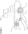
- a heating and cooling plate comprising a housing 1, an insulation plate 2, a cylinder 3 which supports a plate 4 onto which an object (e.g. a beaker of liquid) to be heated or cooled can be placed.
- the plate 4 comprises a material with high thermal conductivity such as copper or aluminium.
- the refrigeration element 6 is arranged to be in direct physical contact with the heating element 5.
- the refrigeration clement is formed as a coil nested in a space formed within the arcuate heating element 5.
- the heating element 5 and refrigeration coil 6 are positioned such that the heating element 5 runs substantially alongside the outermost coil 6, so that they are in direct physical contact.
- the refrigeration element 6 and heating element 5 are arranged within the cylinder 3 such that when the plate 4 is mounted onto the cylinder 3 it is substantially in physical contact with both the refrigeration coil 6 and heating element 5.
- the refrigeration coil 6 forms part of a closed vapour compression refrigeration system which also comprises a compressor 7 for compressing gaseous refrigerant flowing from the refrigeration coil 6, a condenser 8 for condensing compressed refrigerant from the compressor 7, a capillary 9 for controlling the flow of liquid refrigerant into the wider refrigeration coil 6.
- Refrigerant entering the coil 6 evaporates (fully or partially) before flowing back to the compressor 7. The evaporation of the refrigerant provides the cooling effect of the cooling coil 6.
- the heating element is arranged to heat the refrigerant as it flows through an upstream portion of the cooling coil and in particular at or near the exit of the capillary.
- Purposeful direct heating of the refrigerant allows the temperature of the plate 4 to be more precisely controlled, in particular it allows more precise control of the heating and cooling of plate 4 through temperatures including those below ambient over a refrigeration system alone.
- An example of a suitable compressor 7 is a rolling piston rotary gas compressor or a miniature rotary compressor as provided by Aspen Compressor, LLC.
- the compressor 7 is powered by direct current. Its speed is controlled by a control unit 11 (see below) by varying the magnitude of the direct current supplied to it. This is used to vary the flow rate of refrigerant through the system and thus control the cooling power of the refrigeration system.
- a rotatable magnet means 10 for use as part of a magnetic stirrer.
- the rotating magnetic means is located in position central and below the plate 4, at the centre of the cooling coil 6.
- the apparatus further comprises a control unit 11 (shown schematically in Figure 3 ) comprising a processor and associated circuitry.
- a control unit 11 shown schematically in Figure 3
- An example of a suitable unit is the Eurotherm Nanodac Recorder/Controller supplied by Eurotherm Ltd (UK).
- the control unit 11 typically also includes a user interface 11A in order that the control unit 11 can be programmed with conditions for heating/cooling operations, examples of input data may include the target temperature(s), time to hold at a target temperature, and the rate of temperature change (gradients between target temperatures).
- the apparatus also includes a temperature sensor 12A for sensing the temperature of the heating element 5; a temperature sensor 12B for sensing the temperature of the cooling element 6; and a temperature sensor 12C for sensing the temperature of the plate 4.
- Temperature sensors 12A, 12B and 12C which may be resistance thermometers, produce output signals indicative of the respective temperatures measured; these outputs are received by the control unit 11.
- the control unit 11 is programmed, using techniques familiar to persons skilled in the art, e.g. PID or CASCADE, to control the temperature of the plate 4 in view of specific conditions of a heating/cooling operation and in response to the output signals received from the temperature sensors 12A, 12B.
- the control 11 can use one or more of a number of operating methods.
- the control unit 11 can vary the current through the heating element 5 only, to increase or decrease the thermal energy provided by it.
- it can vary the current to the compressor 7 only, in order to vary the cooling power of the refrigeration element 6.
- it controls the current to both the heater element 5 and the compressor 7 together which may preferably be simultaneous. This latter method is particularly effective where it is wished to vary the temperature of the plate precisely or to gradient the temperature of the plate 4 with time. Because a thermally conductive path exists between each of the heating element 5, cooling element 6 and plate 7, thermal energy is transferred to/from the plate very quickly. And because the heating element is located adjacent the exit of the capillary 9, any change in the latent heat from the evaporating refrigerant can, if needed, be offset very quickly.
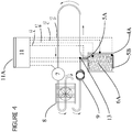
- FIG. 3 & 4 A second embodiment is illustrated in Figures 3 & 4 in which like components are given corresponding numbering.
- the plate 4 is replace by a cylinder or column 4A and the cooling element 6A is formed as a helix nested so as to run alongside and contact the inner wall of the cylinder 4A.
- a heating jacket 5A is arranged substantially around a portion of the cooling element 6A at or adjacent the exit of the capillary 9 in order to heat refrigerant as it enters the cooling element 6A.
- This embodiment also comprises a second heater element 5B which is arranged within the cylinder substantially at one end thereof (in this case the top end).
- a conduit for carrying a fluid to be heated or cooled is positioned (e.g. wrapped) around the outer surface of cylinder 4A.
- the temperature of the outer surface of the cylinder 4A is controlled and varied as before by adjusting the power to the compressor 7 and/or heating element 5A; this is controlled by the control unit 11.
- Heating element 5B can be used where it is desired to provide a temperature profile across the height of the cylinder 4A; when in operation the upper portion will be heated by the heater 5B, whilst the lower portion will remain cooled by cooling element 6B. Varying the power to heating elements 5A, 5B and compressor 7 can be used to vary the temperature profile across the height of the cylinder 4A.
- Figure 5 illustrates an alternative embodiment which is identical to Figure 2 other than the capillary 9 is replaced by a variable valve 15. This may be opened and closed, if necessary to further control the rate of refrigerant flow through the system. Similarly a variable valve may be used in place of the capillary 9 in the embodiment of Figure 3 . In a further embodiment not shown, the control unit 11 may be arranged to control the variable valve 15 instead of the compressor 7. In one method, control of the variable valve is achieved using a fixed voltage and a control signal from control unit 11.
- Figure 6 illustrates a further alternative embodiment provided with a by-pass line 16 which incorporates a capillary or variable valve 16A.
- the function of the by-pass line is to divert a portion of liquid refrigerant passed the refrigeration element 6, and to reintroduce the liquid refrigerant into the conduit between the cooling element 6 and the compressor 7. Once exiting the capillary 16A the refrigerant evaporates thereby reducing the temperature of refrigerant flowing to the compressor 7.
- This feature is thought to be of use when refrigerant in the cooling element may be heated to a temperature that could damage the compressor 7. This may occur when the refrigeration system is being used to cool down the plate from a high temperature.
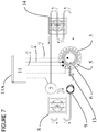
- Figure 7 illustrates a further alternative in which the temperature of refrigerant flowing to the compressor is cooled by passing it through a second heat exchanger 14 subsequent to flowing through the refrigeration element 6.
- the support and housing for the heating element and refrigeration element take forms other than cylindrical.
- the refrigeration element may be shaped other than as a coil.
- the heating element make be shaped other than arcuate so long as it is arranged to run alongside a portion of the refrigeration element.
- heating element and refrigeration elements are shown as tubes with substantially circular cross sections, the element may be formed such that a portion of the surface in contact with the plate 4 and or heating element 5 is planar or flattened. This enables a larger contact area with the surface than an element with a generally circular cross section.
- the surface may be provided by forms other than a plate or cylinder, including but not limited to cuboidal, prism shaped and ovoid.
- the apparatus may comprise multiple closed looped vapour compression refrigeration systems, preferably arranged to work in a cascade in order to achieve lower maximum operating temperatures.
- the arrangement of cascade systems is well known in the art.
- the surface may be formed from a flexible material.
- the surface may be defined from a sheet of flexible material such as silicone, or from a woven or matted material or fibrous material such as glass fibre.
Landscapes
- Engineering & Computer Science (AREA)
- Chemical & Material Sciences (AREA)
- Physics & Mathematics (AREA)
- Mechanical Engineering (AREA)
- Thermal Sciences (AREA)
- General Engineering & Computer Science (AREA)
- Health & Medical Sciences (AREA)
- Chemical Kinetics & Catalysis (AREA)
- Clinical Laboratory Science (AREA)
- Biochemistry (AREA)
- General Health & Medical Sciences (AREA)
- Molecular Biology (AREA)
- Life Sciences & Earth Sciences (AREA)
- Devices That Are Associated With Refrigeration Equipment (AREA)
- General Induction Heating (AREA)
- General Physics & Mathematics (AREA)
- Automation & Control Theory (AREA)
Claims (1)
- Heiz- und Kühlgerät, das aus Folgendem besteht einem:einem Gehäuse (4), das eine erste Oberfläche zum Tragen eines Objekts bietet, das auf der ersten Seite des Gehäuses erwärmt oder gekühlt werden soll;einem Heizgerät mit einem Heizelement (10), um die erste Oberfläche zu erwärmen;einem Kompressionskältesystem bestehend aus einem Verdampfer (6), durch den ein Kühlmittel läuft, um die erste Oberfläche zu kühlen;einem Mittel, um die Temperatur der ersten Oberfläche und/oder des Objekts sowie die Temperatur im Zusammenhang mit mindestens einem der Heizelemente (5) und dem Verdampfer (6) zu messen und Signale auszugeben, die diese Temperaturen anzeigen;einem Kontrollmittel (1), um die Ausgabesignale zu empfangen und in Reaktion darauf den Betrieb des Heizgeräts (5) und des Kühlgeräts zu regeln, um die Temperatur der ersten Oberfläche zu regeln; undCharakterisiert davon, dass sich das Heizgerät (5) und der Verdampfer (6) neben einer zweiten Oberfläche im Gehäuse (4) auf der anderen Seite des zu erwärmenden oder zu kühlenden Objekts befinden, wobei das Heizgerät (4) und der Verdampfer (6) in direktem Kontakt mit der zweiten Gehäuseoberfläche und miteinander stehen.
Applications Claiming Priority (3)
| Application Number | Priority Date | Filing Date | Title |
|---|---|---|---|
| GBGB1118339.9A GB201118339D0 (en) | 2011-10-24 | 2011-10-24 | Heating and cooling apparatus |
| GB1120379.1A GB2499972B (en) | 2011-10-24 | 2011-11-25 | Heating and cooling apparatus |
| PCT/GB2012/052623 WO2013061043A2 (en) | 2011-10-24 | 2012-10-23 | Heating and cooling apparatus |
Publications (2)
| Publication Number | Publication Date |
|---|---|
| EP2771629A2 EP2771629A2 (de) | 2014-09-03 |
| EP2771629B1 true EP2771629B1 (de) | 2020-05-27 |
Family
ID=45373329
Family Applications (1)
| Application Number | Title | Priority Date | Filing Date |
|---|---|---|---|
| EP12787833.8A Active EP2771629B1 (de) | 2011-10-24 | 2012-10-23 | Heiz- und kühlvorrichtung |
Country Status (4)
| Country | Link |
|---|---|
| US (1) | US10065162B2 (de) |
| EP (1) | EP2771629B1 (de) |
| GB (2) | GB201118339D0 (de) |
| WO (1) | WO2013061043A2 (de) |
Families Citing this family (3)
| Publication number | Priority date | Publication date | Assignee | Title |
|---|---|---|---|---|
| US9759451B2 (en) * | 2013-11-22 | 2017-09-12 | Thermo Fisher Scientific (Asheville) Llc | Recirculating bath |
| CN116045715B (zh) * | 2023-01-09 | 2023-07-18 | 浙江志高动力科技有限公司 | 一种节能螺杆空压机 |
| WO2025264556A2 (en) * | 2024-06-18 | 2025-12-26 | Coopersurgical, Inc. | Laboratory workstation |
Citations (3)
| Publication number | Priority date | Publication date | Assignee | Title |
|---|---|---|---|---|
| US5977785A (en) * | 1996-05-28 | 1999-11-02 | Burward-Hoy; Trevor | Method and apparatus for rapidly varying the operating temperature of a semiconductor device in a testing environment |
| US20070013394A1 (en) * | 2004-02-16 | 2007-01-18 | Unisys Corporation | Dual feedback control system for maintaining the temperature of an ic-chip near a set-point |
| US20070058350A1 (en) * | 2005-09-09 | 2007-03-15 | Satoshi Nakamura | Temperature control unit for electronic component and handler apparatus |
Family Cites Families (31)
| Publication number | Priority date | Publication date | Assignee | Title |
|---|---|---|---|---|
| US3333829A (en) * | 1966-04-21 | 1967-08-01 | Thermolyne Corp | Magnetic stirrer and temperature regulation device |
| DE8802673U1 (de) * | 1988-03-01 | 1988-04-21 | Bühler Meß- und Regeltechnik GmbH & Co KG, 4030 Ratingen | Kleinbauender Gaskühler für Meßgase |
| US4913985A (en) * | 1989-02-21 | 1990-04-03 | Zomeworks Corporation | Battery temperature regulation system |
| US5316872A (en) * | 1992-12-03 | 1994-05-31 | Zomeworks Corporation | Passive cooling system |
| US5529391A (en) * | 1994-09-22 | 1996-06-25 | Duke University | Magnetic stirring and heating/cooling apparatus |
| US6012383A (en) * | 1997-06-09 | 2000-01-11 | Lande`; Arnold J. | Home yogurt/cheese making machine |
| US6415858B1 (en) * | 1997-12-31 | 2002-07-09 | Temptronic Corporation | Temperature control system for a workpiece chuck |
| JP3909364B2 (ja) * | 1998-10-29 | 2007-04-25 | Dowaエレクトロニクス株式会社 | ガリウムの精製方法および装置 |
| US6324857B1 (en) * | 1998-12-01 | 2001-12-04 | Julabo Labortechnik Gmbh | Laboratory thermostat |
| US6184504B1 (en) * | 1999-04-13 | 2001-02-06 | Silicon Thermal, Inc. | Temperature control system for electronic devices |
| JP3973853B2 (ja) * | 2001-03-28 | 2007-09-12 | 大日本スクリーン製造株式会社 | 熱処理装置 |
| US6668570B2 (en) * | 2001-05-31 | 2003-12-30 | Kryotech, Inc. | Apparatus and method for controlling the temperature of an electronic device under test |
| SE0102280D0 (sv) * | 2001-06-27 | 2001-06-27 | Implementa Hebe Ab | A device in performing a process in a process medium |
| CA2363476C (en) * | 2001-11-20 | 2010-06-08 | Udo Hendrick Verkerk | A device for the addition of a compound or compound mixture to another under various reaction conditions, parallel or otherwise |
| KR100436657B1 (ko) * | 2001-12-17 | 2004-06-22 | 미래산업 주식회사 | 반도체 소자 테스트 핸들러의 소자 가열 및 냉각장치 |
| US6938432B2 (en) | 2002-01-10 | 2005-09-06 | Espec Corp. | Cooling apparatus and a thermostat with the apparatus installed therein |
| US7100389B1 (en) * | 2002-07-16 | 2006-09-05 | Delta Design, Inc. | Apparatus and method having mechanical isolation arrangement for controlling the temperature of an electronic device under test |
| US20080029248A1 (en) * | 2006-03-13 | 2008-02-07 | Sage Science, Inc. | Laboratory Temperature Control With Ultra-Smooth Heat Transfer Surfaces |
| US20070240870A1 (en) * | 2006-04-18 | 2007-10-18 | Daytona Control Co., Ltd. | Temperature control apparatus |
| US8232091B2 (en) * | 2006-05-17 | 2012-07-31 | California Institute Of Technology | Thermal cycling system |
| US7520657B2 (en) * | 2006-07-14 | 2009-04-21 | Sigma-Aldrich Co. | Magnetic stirrer |
| JP4564973B2 (ja) * | 2007-01-26 | 2010-10-20 | 株式会社日立ハイテクノロジーズ | プラズマ処理装置 |
| US8151872B2 (en) * | 2007-03-16 | 2012-04-10 | Centipede Systems, Inc. | Method and apparatus for controlling temperature |
| KR101307859B1 (ko) * | 2007-07-19 | 2013-09-12 | 삼성전자주식회사 | 생화학 분석기 및 그 내부 온도 제어 방법 |
| TW200920475A (en) * | 2007-11-02 | 2009-05-16 | Plus Lab Technology Co Ltd A | Electromagnetic stirring device |
| US8424594B2 (en) * | 2007-12-10 | 2013-04-23 | Presto Engineering, Inc. | Apparatus for thermal control in the analysis of electronic devices |
| DE112008003714T5 (de) * | 2008-10-29 | 2010-11-25 | Advantest Corp. | Temperatursteuerung für elektronische Bauelemente |
| US9121628B2 (en) * | 2009-06-02 | 2015-09-01 | Nortek Global Hvac Llc | Heat pumps with unequal cooling and heating capacities for climates where demand for cooling and heating are unequal, and method of adapting and distributing such heat pumps |
| US8317910B2 (en) * | 2010-03-22 | 2012-11-27 | Unity Semiconductor Corporation | Immersion platinum plating solution |
| JP2014215062A (ja) * | 2013-04-23 | 2014-11-17 | セイコーエプソン株式会社 | ハンドラーおよび検査装置 |
| DE102013010275C5 (de) * | 2013-06-18 | 2016-09-15 | Ika-Werke Gmbh & Co. Kg | Magnetrührer mit SAW-Sensor |
-
2011
- 2011-10-24 GB GBGB1118339.9A patent/GB201118339D0/en not_active Ceased
- 2011-11-25 GB GB1120379.1A patent/GB2499972B/en not_active Expired - Fee Related
-
2012
- 2012-10-23 WO PCT/GB2012/052623 patent/WO2013061043A2/en not_active Ceased
- 2012-10-23 US US14/353,501 patent/US10065162B2/en active Active
- 2012-10-23 EP EP12787833.8A patent/EP2771629B1/de active Active
Patent Citations (3)
| Publication number | Priority date | Publication date | Assignee | Title |
|---|---|---|---|---|
| US5977785A (en) * | 1996-05-28 | 1999-11-02 | Burward-Hoy; Trevor | Method and apparatus for rapidly varying the operating temperature of a semiconductor device in a testing environment |
| US20070013394A1 (en) * | 2004-02-16 | 2007-01-18 | Unisys Corporation | Dual feedback control system for maintaining the temperature of an ic-chip near a set-point |
| US20070058350A1 (en) * | 2005-09-09 | 2007-03-15 | Satoshi Nakamura | Temperature control unit for electronic component and handler apparatus |
Also Published As
| Publication number | Publication date |
|---|---|
| GB2499972A (en) | 2013-09-11 |
| GB2499972B (en) | 2015-10-07 |
| GB201120379D0 (en) | 2012-01-11 |
| WO2013061043A2 (en) | 2013-05-02 |
| US20140290927A1 (en) | 2014-10-02 |
| GB201118339D0 (en) | 2011-12-07 |
| WO2013061043A3 (en) | 2013-10-03 |
| US10065162B2 (en) | 2018-09-04 |
| EP2771629A2 (de) | 2014-09-03 |
Similar Documents
| Publication | Publication Date | Title |
|---|---|---|
| CN101842679B (zh) | 温度控制设备 | |
| Dong et al. | An experimental study on defrosting heat supplies and energy consumptions during a reverse cycle defrost operation for an air source heat pump | |
| CN103781550B (zh) | 冷却/加热装置 | |
| CA3057475C (en) | TEMPERATURE CONTROL DEVICE AND METHOD | |
| Lin et al. | Experiment investigation of a two-stage thermoelectric cooler under current pulse operation | |
| CN212905287U (zh) | 一种测试装置 | |
| Song et al. | An experimental study on the uneven refrigerant distribution over a vertically installed multi-circuit outdoor coil in an air source heat pump unit during reverse cycle defrosting | |
| US10065162B2 (en) | Heating and cooling apparatus | |
| He et al. | Experimental study of a miniature vapor compression refrigeration system with two heat sink evaporators connected in series or in parallel | |
| CN114441589A (zh) | 测量仪、运行测量仪的方法及珀耳帖元件的应用 | |
| Çağlar | Design and experimental investigation of a novel thermoelectric water dispenser unit | |
| US7293449B2 (en) | Thermal modulation for gas chromatography | |
| CN218917254U (zh) | 一种用于测量相变储能构件热性能的装置 | |
| CN100552445C (zh) | 热管性能检测装置 | |
| CN100573126C (zh) | 热管性能检测装置 | |
| WO2016025985A1 (en) | Method and system of rapid heating and cooling of a fluid | |
| CN2814557Y (zh) | 半导体热电效应教学演示仪 | |
| JP2006043077A5 (de) | ||
| CN208043758U (zh) | 一种色谱柱恒温加热装置 | |
| Ducoulombier et al. | Charge reduction experimental investigation of CO2 single-phase flow in a horizontal micro-channel with constant heat flux conditions | |
| CN207488852U (zh) | 一种气体恒温装置及检测系统 | |
| JP2007527013A (ja) | ガスクロマトグラフィーのための熱調節 | |
| RU2659840C1 (ru) | Стенд для исследования параметров функционирования бытовых тепловых насосов | |
| Szaszák et al. | Experimental investigation of a high efficiency electric heater and dehumidifier prototype unit | |
| JPH08159993A (ja) | 蒸溜試験用恒温装置 |
Legal Events
| Date | Code | Title | Description |
|---|---|---|---|
| PUAI | Public reference made under article 153(3) epc to a published international application that has entered the european phase |
Free format text: ORIGINAL CODE: 0009012 |
|
| 17P | Request for examination filed |
Effective date: 20140526 |
|
| AK | Designated contracting states |
Kind code of ref document: A2 Designated state(s): AL AT BE BG CH CY CZ DE DK EE ES FI FR GB GR HR HU IE IS IT LI LT LU LV MC MK MT NL NO PL PT RO RS SE SI SK SM TR |
|
| DAX | Request for extension of the european patent (deleted) | ||
| STAA | Information on the status of an ep patent application or granted ep patent |
Free format text: STATUS: EXAMINATION IS IN PROGRESS |
|
| 17Q | First examination report despatched |
Effective date: 20170720 |
|
| REG | Reference to a national code |
Ref country code: DE Ref legal event code: R079 Ref document number: 602012070357 Country of ref document: DE Free format text: PREVIOUS MAIN CLASS: F25B0041000000 Ipc: B01L0007000000 |
|
| GRAP | Despatch of communication of intention to grant a patent |
Free format text: ORIGINAL CODE: EPIDOSNIGR1 |
|
| STAA | Information on the status of an ep patent application or granted ep patent |
Free format text: STATUS: GRANT OF PATENT IS INTENDED |
|
| RIC1 | Information provided on ipc code assigned before grant |
Ipc: B01L 7/00 20060101AFI20191112BHEP Ipc: F25B 49/02 20060101ALI20191112BHEP |
|
| INTG | Intention to grant announced |
Effective date: 20191211 |
|
| GRAS | Grant fee paid |
Free format text: ORIGINAL CODE: EPIDOSNIGR3 |
|
| GRAA | (expected) grant |
Free format text: ORIGINAL CODE: 0009210 |
|
| STAA | Information on the status of an ep patent application or granted ep patent |
Free format text: STATUS: THE PATENT HAS BEEN GRANTED |
|
| AK | Designated contracting states |
Kind code of ref document: B1 Designated state(s): AL AT BE BG CH CY CZ DE DK EE ES FI FR GB GR HR HU IE IS IT LI LT LU LV MC MK MT NL NO PL PT RO RS SE SI SK SM TR |
|
| REG | Reference to a national code |
Ref country code: GB Ref legal event code: FG4D |
|
| REG | Reference to a national code |
Ref country code: CH Ref legal event code: EP |
|
| REG | Reference to a national code |
Ref country code: AT Ref legal event code: REF Ref document number: 1273987 Country of ref document: AT Kind code of ref document: T Effective date: 20200615 |
|
| REG | Reference to a national code |
Ref country code: DE Ref legal event code: R096 Ref document number: 602012070357 Country of ref document: DE |
|
| REG | Reference to a national code |
Ref country code: LT Ref legal event code: MG4D |
|
| PG25 | Lapsed in a contracting state [announced via postgrant information from national office to epo] |
Ref country code: LT Free format text: LAPSE BECAUSE OF FAILURE TO SUBMIT A TRANSLATION OF THE DESCRIPTION OR TO PAY THE FEE WITHIN THE PRESCRIBED TIME-LIMIT Effective date: 20200527 Ref country code: NO Free format text: LAPSE BECAUSE OF FAILURE TO SUBMIT A TRANSLATION OF THE DESCRIPTION OR TO PAY THE FEE WITHIN THE PRESCRIBED TIME-LIMIT Effective date: 20200827 Ref country code: GR Free format text: LAPSE BECAUSE OF FAILURE TO SUBMIT A TRANSLATION OF THE DESCRIPTION OR TO PAY THE FEE WITHIN THE PRESCRIBED TIME-LIMIT Effective date: 20200828 Ref country code: SE Free format text: LAPSE BECAUSE OF FAILURE TO SUBMIT A TRANSLATION OF THE DESCRIPTION OR TO PAY THE FEE WITHIN THE PRESCRIBED TIME-LIMIT Effective date: 20200527 Ref country code: PT Free format text: LAPSE BECAUSE OF FAILURE TO SUBMIT A TRANSLATION OF THE DESCRIPTION OR TO PAY THE FEE WITHIN THE PRESCRIBED TIME-LIMIT Effective date: 20200928 Ref country code: FI Free format text: LAPSE BECAUSE OF FAILURE TO SUBMIT A TRANSLATION OF THE DESCRIPTION OR TO PAY THE FEE WITHIN THE PRESCRIBED TIME-LIMIT Effective date: 20200527 Ref country code: IS Free format text: LAPSE BECAUSE OF FAILURE TO SUBMIT A TRANSLATION OF THE DESCRIPTION OR TO PAY THE FEE WITHIN THE PRESCRIBED TIME-LIMIT Effective date: 20200927 |
|
| REG | Reference to a national code |
Ref country code: NL Ref legal event code: MP Effective date: 20200527 |
|
| PG25 | Lapsed in a contracting state [announced via postgrant information from national office to epo] |
Ref country code: HR Free format text: LAPSE BECAUSE OF FAILURE TO SUBMIT A TRANSLATION OF THE DESCRIPTION OR TO PAY THE FEE WITHIN THE PRESCRIBED TIME-LIMIT Effective date: 20200527 Ref country code: LV Free format text: LAPSE BECAUSE OF FAILURE TO SUBMIT A TRANSLATION OF THE DESCRIPTION OR TO PAY THE FEE WITHIN THE PRESCRIBED TIME-LIMIT Effective date: 20200527 Ref country code: BG Free format text: LAPSE BECAUSE OF FAILURE TO SUBMIT A TRANSLATION OF THE DESCRIPTION OR TO PAY THE FEE WITHIN THE PRESCRIBED TIME-LIMIT Effective date: 20200827 Ref country code: RS Free format text: LAPSE BECAUSE OF FAILURE TO SUBMIT A TRANSLATION OF THE DESCRIPTION OR TO PAY THE FEE WITHIN THE PRESCRIBED TIME-LIMIT Effective date: 20200527 |
|
| REG | Reference to a national code |
Ref country code: AT Ref legal event code: MK05 Ref document number: 1273987 Country of ref document: AT Kind code of ref document: T Effective date: 20200527 |
|
| PG25 | Lapsed in a contracting state [announced via postgrant information from national office to epo] |
Ref country code: NL Free format text: LAPSE BECAUSE OF FAILURE TO SUBMIT A TRANSLATION OF THE DESCRIPTION OR TO PAY THE FEE WITHIN THE PRESCRIBED TIME-LIMIT Effective date: 20200527 Ref country code: AL Free format text: LAPSE BECAUSE OF FAILURE TO SUBMIT A TRANSLATION OF THE DESCRIPTION OR TO PAY THE FEE WITHIN THE PRESCRIBED TIME-LIMIT Effective date: 20200527 |
|
| PG25 | Lapsed in a contracting state [announced via postgrant information from national office to epo] |
Ref country code: CZ Free format text: LAPSE BECAUSE OF FAILURE TO SUBMIT A TRANSLATION OF THE DESCRIPTION OR TO PAY THE FEE WITHIN THE PRESCRIBED TIME-LIMIT Effective date: 20200527 Ref country code: RO Free format text: LAPSE BECAUSE OF FAILURE TO SUBMIT A TRANSLATION OF THE DESCRIPTION OR TO PAY THE FEE WITHIN THE PRESCRIBED TIME-LIMIT Effective date: 20200527 Ref country code: AT Free format text: LAPSE BECAUSE OF FAILURE TO SUBMIT A TRANSLATION OF THE DESCRIPTION OR TO PAY THE FEE WITHIN THE PRESCRIBED TIME-LIMIT Effective date: 20200527 Ref country code: DK Free format text: LAPSE BECAUSE OF FAILURE TO SUBMIT A TRANSLATION OF THE DESCRIPTION OR TO PAY THE FEE WITHIN THE PRESCRIBED TIME-LIMIT Effective date: 20200527 Ref country code: IT Free format text: LAPSE BECAUSE OF FAILURE TO SUBMIT A TRANSLATION OF THE DESCRIPTION OR TO PAY THE FEE WITHIN THE PRESCRIBED TIME-LIMIT Effective date: 20200527 Ref country code: EE Free format text: LAPSE BECAUSE OF FAILURE TO SUBMIT A TRANSLATION OF THE DESCRIPTION OR TO PAY THE FEE WITHIN THE PRESCRIBED TIME-LIMIT Effective date: 20200527 Ref country code: SM Free format text: LAPSE BECAUSE OF FAILURE TO SUBMIT A TRANSLATION OF THE DESCRIPTION OR TO PAY THE FEE WITHIN THE PRESCRIBED TIME-LIMIT Effective date: 20200527 Ref country code: ES Free format text: LAPSE BECAUSE OF FAILURE TO SUBMIT A TRANSLATION OF THE DESCRIPTION OR TO PAY THE FEE WITHIN THE PRESCRIBED TIME-LIMIT Effective date: 20200527 |
|
| PG25 | Lapsed in a contracting state [announced via postgrant information from national office to epo] |
Ref country code: SK Free format text: LAPSE BECAUSE OF FAILURE TO SUBMIT A TRANSLATION OF THE DESCRIPTION OR TO PAY THE FEE WITHIN THE PRESCRIBED TIME-LIMIT Effective date: 20200527 Ref country code: PL Free format text: LAPSE BECAUSE OF FAILURE TO SUBMIT A TRANSLATION OF THE DESCRIPTION OR TO PAY THE FEE WITHIN THE PRESCRIBED TIME-LIMIT Effective date: 20200527 |
|
| REG | Reference to a national code |
Ref country code: DE Ref legal event code: R097 Ref document number: 602012070357 Country of ref document: DE |
|
| PLBE | No opposition filed within time limit |
Free format text: ORIGINAL CODE: 0009261 |
|
| STAA | Information on the status of an ep patent application or granted ep patent |
Free format text: STATUS: NO OPPOSITION FILED WITHIN TIME LIMIT |
|
| 26N | No opposition filed |
Effective date: 20210302 |
|
| PG25 | Lapsed in a contracting state [announced via postgrant information from national office to epo] |
Ref country code: SI Free format text: LAPSE BECAUSE OF FAILURE TO SUBMIT A TRANSLATION OF THE DESCRIPTION OR TO PAY THE FEE WITHIN THE PRESCRIBED TIME-LIMIT Effective date: 20200527 |
|
| PG25 | Lapsed in a contracting state [announced via postgrant information from national office to epo] |
Ref country code: LU Free format text: LAPSE BECAUSE OF NON-PAYMENT OF DUE FEES Effective date: 20201023 Ref country code: MC Free format text: LAPSE BECAUSE OF FAILURE TO SUBMIT A TRANSLATION OF THE DESCRIPTION OR TO PAY THE FEE WITHIN THE PRESCRIBED TIME-LIMIT Effective date: 20200527 |
|
| REG | Reference to a national code |
Ref country code: BE Ref legal event code: MM Effective date: 20201031 |
|
| PG25 | Lapsed in a contracting state [announced via postgrant information from national office to epo] |
Ref country code: BE Free format text: LAPSE BECAUSE OF NON-PAYMENT OF DUE FEES Effective date: 20201031 |
|
| PG25 | Lapsed in a contracting state [announced via postgrant information from national office to epo] |
Ref country code: IE Free format text: LAPSE BECAUSE OF NON-PAYMENT OF DUE FEES Effective date: 20201023 |
|
| PG25 | Lapsed in a contracting state [announced via postgrant information from national office to epo] |
Ref country code: TR Free format text: LAPSE BECAUSE OF FAILURE TO SUBMIT A TRANSLATION OF THE DESCRIPTION OR TO PAY THE FEE WITHIN THE PRESCRIBED TIME-LIMIT Effective date: 20200527 Ref country code: MT Free format text: LAPSE BECAUSE OF FAILURE TO SUBMIT A TRANSLATION OF THE DESCRIPTION OR TO PAY THE FEE WITHIN THE PRESCRIBED TIME-LIMIT Effective date: 20200527 Ref country code: CY Free format text: LAPSE BECAUSE OF FAILURE TO SUBMIT A TRANSLATION OF THE DESCRIPTION OR TO PAY THE FEE WITHIN THE PRESCRIBED TIME-LIMIT Effective date: 20200527 |
|
| PG25 | Lapsed in a contracting state [announced via postgrant information from national office to epo] |
Ref country code: MK Free format text: LAPSE BECAUSE OF FAILURE TO SUBMIT A TRANSLATION OF THE DESCRIPTION OR TO PAY THE FEE WITHIN THE PRESCRIBED TIME-LIMIT Effective date: 20200527 |
|
| PGFP | Annual fee paid to national office [announced via postgrant information from national office to epo] |
Ref country code: GB Payment date: 20250801 Year of fee payment: 14 |
|
| REG | Reference to a national code |
Ref country code: CH Ref legal event code: U11 Free format text: ST27 STATUS EVENT CODE: U-0-0-U10-U11 (AS PROVIDED BY THE NATIONAL OFFICE) Effective date: 20251101 |
|
| PGFP | Annual fee paid to national office [announced via postgrant information from national office to epo] |
Ref country code: DE Payment date: 20251021 Year of fee payment: 14 |
|
| PGFP | Annual fee paid to national office [announced via postgrant information from national office to epo] |
Ref country code: FR Payment date: 20251030 Year of fee payment: 14 |
|
| PGFP | Annual fee paid to national office [announced via postgrant information from national office to epo] |
Ref country code: CH Payment date: 20251101 Year of fee payment: 14 |