EP2771735B1 - Schaltelement enthaltend ein flüssigkristallines medium - Google Patents
Schaltelement enthaltend ein flüssigkristallines medium Download PDFInfo
- Publication number
- EP2771735B1 EP2771735B1 EP12762537.4A EP12762537A EP2771735B1 EP 2771735 B1 EP2771735 B1 EP 2771735B1 EP 12762537 A EP12762537 A EP 12762537A EP 2771735 B1 EP2771735 B1 EP 2771735B1
- Authority
- EP
- European Patent Office
- Prior art keywords
- switching
- switching element
- state
- polymer
- element according
- Prior art date
- Legal status (The legal status is an assumption and is not a legal conclusion. Google has not performed a legal analysis and makes no representation as to the accuracy of the status listed.)
- Active
Links
- 0 Cc(cc1)c(*)c2c1cc(C)c(*)c2* Chemical compound Cc(cc1)c(*)c2c1cc(C)c(*)c2* 0.000 description 5
- AEWMNNRDWLVIAU-UHFFFAOYSA-N C=CC(OCCCCCCOc(cc1)ccc1C(Oc(c(Cl)c1)ccc1C(Oc(cc1)ccc1Cl)=O)=O)=O Chemical compound C=CC(OCCCCCCOc(cc1)ccc1C(Oc(c(Cl)c1)ccc1C(Oc(cc1)ccc1Cl)=O)=O)=O AEWMNNRDWLVIAU-UHFFFAOYSA-N 0.000 description 1
- HKWAGUXHFSLUCQ-UHFFFAOYSA-N C=CC(OCCCCCCOc(cc1)ccc1C(Oc(cc1F)ccc1C#N)=O)=O Chemical compound C=CC(OCCCCCCOc(cc1)ccc1C(Oc(cc1F)ccc1C#N)=O)=O HKWAGUXHFSLUCQ-UHFFFAOYSA-N 0.000 description 1
- MOBIJHKDPCBKER-UHFFFAOYSA-N C=CC(OCCCCc(cc1)cc(F)c1-c(cc1)cc(F)c1-c(cc1)ccc1OCCCOC(C=C)=O)=O Chemical compound C=CC(OCCCCc(cc1)cc(F)c1-c(cc1)cc(F)c1-c(cc1)ccc1OCCCOC(C=C)=O)=O MOBIJHKDPCBKER-UHFFFAOYSA-N 0.000 description 1
- UIPCFCKRODGMCO-UHFFFAOYSA-N CC(C(OC1CCC(COc(cc2)ccc2OC(C(C)=C)=O)CC1)=O)=C Chemical compound CC(C(OC1CCC(COc(cc2)ccc2OC(C(C)=C)=O)CC1)=O)=C UIPCFCKRODGMCO-UHFFFAOYSA-N 0.000 description 1
- FGZHYXRKFBKXFI-UHFFFAOYSA-N CC(C(OCCCCCCOc(cc1)ccc1-c(cc1)ccc1OCCCCCCOC(C(C)=C)=O)=O)=C Chemical compound CC(C(OCCCCCCOc(cc1)ccc1-c(cc1)ccc1OCCCCCCOC(C(C)=C)=O)=O)=C FGZHYXRKFBKXFI-UHFFFAOYSA-N 0.000 description 1
- OGJZTZNJRBMEDM-UHFFFAOYSA-N CC(C(OCCCCc1cc(F)c(C(Oc(cc2)cc(F)c2OC(c(c(F)cc(CCCCOC(C(C)=C)=O)c2)c2F)(F)F)(F)F)c(F)c1)=O)=C Chemical compound CC(C(OCCCCc1cc(F)c(C(Oc(cc2)cc(F)c2OC(c(c(F)cc(CCCCOC(C(C)=C)=O)c2)c2F)(F)F)(F)F)c(F)c1)=O)=C OGJZTZNJRBMEDM-UHFFFAOYSA-N 0.000 description 1
- GMZDMQMQYGRCJX-UHFFFAOYSA-N CC(C(OCCCc(cc1)cc(ccc2c3)c1c2ccc3OC(C(C)=C)=O)=O)=C Chemical compound CC(C(OCCCc(cc1)cc(ccc2c3)c1c2ccc3OC(C(C)=C)=O)=O)=C GMZDMQMQYGRCJX-UHFFFAOYSA-N 0.000 description 1
- GFWWCTXLXFTWOH-UHFFFAOYSA-N CC(C(Oc(cc1)ccc1Oc(cc1)ccc1-c(cc1)ccc1Oc(cc1)ccc1OC(C(C)=C)=O)=O)=C Chemical compound CC(C(Oc(cc1)ccc1Oc(cc1)ccc1-c(cc1)ccc1Oc(cc1)ccc1OC(C(C)=C)=O)=O)=C GFWWCTXLXFTWOH-UHFFFAOYSA-N 0.000 description 1
- FNWSLRDIODUVTH-ZRTSHPBBSA-N CC/C=C(\CC1)/CC[C@H]1c(cc1)ccc1-c1cc(F)c(CCCCOC(C(C)=C)=O)c(F)c1 Chemical compound CC/C=C(\CC1)/CC[C@H]1c(cc1)ccc1-c1cc(F)c(CCCCOC(C(C)=C)=O)c(F)c1 FNWSLRDIODUVTH-ZRTSHPBBSA-N 0.000 description 1
- PSXLLJKEGOBZGY-UHFFFAOYSA-N CCC1COC(c(cc2)ccc2OCCCOC(C=C)=O)OC1 Chemical compound CCC1COC(c(cc2)ccc2OCCCOC(C=C)=O)OC1 PSXLLJKEGOBZGY-UHFFFAOYSA-N 0.000 description 1
- YMUKRYIUVCBGFA-UHFFFAOYSA-N CCCC(CC1)CCC1C(CC1)CCC1c(cc1F)cc(F)c1OCCCCCCOC(C=C)=O Chemical compound CCCC(CC1)CCC1C(CC1)CCC1c(cc1F)cc(F)c1OCCCCCCOC(C=C)=O YMUKRYIUVCBGFA-UHFFFAOYSA-N 0.000 description 1
- NEGMGVQULWEOID-UHFFFAOYSA-N CCCCCC(CC1)CCC1C(CC1)CCC1OC(c(cc1)ccc1OCCCOC(C=C)=O)=O Chemical compound CCCCCC(CC1)CCC1C(CC1)CCC1OC(c(cc1)ccc1OCCCOC(C=C)=O)=O NEGMGVQULWEOID-UHFFFAOYSA-N 0.000 description 1
- FBLQNCONXAKONL-UHFFFAOYSA-N CCCCCCCc(cc1)cc(F)c1OC(c(cc1)ccc1-c(cc1)ccc1OCCCCCCOC(C=C)=O)=O Chemical compound CCCCCCCc(cc1)cc(F)c1OC(c(cc1)ccc1-c(cc1)ccc1OCCCCCCOC(C=C)=O)=O FBLQNCONXAKONL-UHFFFAOYSA-N 0.000 description 1
- RUFITJSEYSHIPC-UHFFFAOYSA-N CCCc(cc1)ccc1-c(cc1)ccc1C(OCCCCCCOC(C=C)=O)=O Chemical compound CCCc(cc1)ccc1-c(cc1)ccc1C(OCCCCCCOC(C=C)=O)=O RUFITJSEYSHIPC-UHFFFAOYSA-N 0.000 description 1
- SAXISFJZKAZSGT-UHFFFAOYSA-N Cc(cc(cc1)C#Cc(cc2)ccc2OC)c1OC(c(cc1)ccc1OCCCCCCOC(C=C)=O)=O Chemical compound Cc(cc(cc1)C#Cc(cc2)ccc2OC)c1OC(c(cc1)ccc1OCCCCCCOC(C=C)=O)=O SAXISFJZKAZSGT-UHFFFAOYSA-N 0.000 description 1
- XAADNLKYQLEUHR-UHFFFAOYSA-N Cc(cc(cc1)OC(c(c(F)cc(CCCCCOC(C=C)=O)c2)c2F)(F)F)c1OC(c(c(F)cc(CCCCCOC(C=C)=O)c1)c1F)(F)F Chemical compound Cc(cc(cc1)OC(c(c(F)cc(CCCCCOC(C=C)=O)c2)c2F)(F)F)c1OC(c(c(F)cc(CCCCCOC(C=C)=O)c1)c1F)(F)F XAADNLKYQLEUHR-UHFFFAOYSA-N 0.000 description 1
Images

Classifications
-
- G—PHYSICS
- G02—OPTICS
- G02F—OPTICAL DEVICES OR ARRANGEMENTS FOR THE CONTROL OF LIGHT BY MODIFICATION OF THE OPTICAL PROPERTIES OF THE MEDIA OF THE ELEMENTS INVOLVED THEREIN; NON-LINEAR OPTICS; FREQUENCY-CHANGING OF LIGHT; OPTICAL LOGIC ELEMENTS; OPTICAL ANALOGUE/DIGITAL CONVERTERS
- G02F1/00—Devices or arrangements for the control of the intensity, colour, phase, polarisation or direction of light arriving from an independent light source, e.g. switching, gating or modulating; Non-linear optics
- G02F1/01—Devices or arrangements for the control of the intensity, colour, phase, polarisation or direction of light arriving from an independent light source, e.g. switching, gating or modulating; Non-linear optics for the control of the intensity, phase, polarisation or colour
- G02F1/13—Devices or arrangements for the control of the intensity, colour, phase, polarisation or direction of light arriving from an independent light source, e.g. switching, gating or modulating; Non-linear optics for the control of the intensity, phase, polarisation or colour based on liquid crystals, e.g. single liquid crystal display cells
- G02F1/132—Thermal activation of liquid crystals exhibiting a thermo-optic effect
-
- C—CHEMISTRY; METALLURGY
- C09—DYES; PAINTS; POLISHES; NATURAL RESINS; ADHESIVES; COMPOSITIONS NOT OTHERWISE PROVIDED FOR; APPLICATIONS OF MATERIALS NOT OTHERWISE PROVIDED FOR
- C09K—MATERIALS FOR MISCELLANEOUS APPLICATIONS, NOT PROVIDED FOR ELSEWHERE
- C09K19/00—Liquid crystal materials
- C09K19/04—Liquid crystal materials characterised by the chemical structure of the liquid crystal components, e.g. by a specific unit
- C09K19/06—Non-steroidal liquid crystal compounds
- C09K19/08—Non-steroidal liquid crystal compounds containing at least two non-condensed rings
- C09K19/30—Non-steroidal liquid crystal compounds containing at least two non-condensed rings containing saturated or unsaturated non-aromatic rings, e.g. cyclohexane rings
- C09K19/3001—Cyclohexane rings
- C09K19/3066—Cyclohexane rings in which the rings are linked by a chain containing carbon and oxygen atoms, e.g. esters or ethers
- C09K19/3068—Cyclohexane rings in which the rings are linked by a chain containing carbon and oxygen atoms, e.g. esters or ethers chain containing -COO- or -OCO- groups
-
- C—CHEMISTRY; METALLURGY
- C09—DYES; PAINTS; POLISHES; NATURAL RESINS; ADHESIVES; COMPOSITIONS NOT OTHERWISE PROVIDED FOR; APPLICATIONS OF MATERIALS NOT OTHERWISE PROVIDED FOR
- C09K—MATERIALS FOR MISCELLANEOUS APPLICATIONS, NOT PROVIDED FOR ELSEWHERE
- C09K19/00—Liquid crystal materials
- C09K19/04—Liquid crystal materials characterised by the chemical structure of the liquid crystal components, e.g. by a specific unit
- C09K19/38—Polymers
-
- C—CHEMISTRY; METALLURGY
- C09—DYES; PAINTS; POLISHES; NATURAL RESINS; ADHESIVES; COMPOSITIONS NOT OTHERWISE PROVIDED FOR; APPLICATIONS OF MATERIALS NOT OTHERWISE PROVIDED FOR
- C09K—MATERIALS FOR MISCELLANEOUS APPLICATIONS, NOT PROVIDED FOR ELSEWHERE
- C09K19/00—Liquid crystal materials
- C09K19/04—Liquid crystal materials characterised by the chemical structure of the liquid crystal components, e.g. by a specific unit
- C09K19/42—Mixtures of liquid crystal compounds covered by two or more of the preceding groups C09K19/06 - C09K19/40
-
- C—CHEMISTRY; METALLURGY
- C09—DYES; PAINTS; POLISHES; NATURAL RESINS; ADHESIVES; COMPOSITIONS NOT OTHERWISE PROVIDED FOR; APPLICATIONS OF MATERIALS NOT OTHERWISE PROVIDED FOR
- C09K—MATERIALS FOR MISCELLANEOUS APPLICATIONS, NOT PROVIDED FOR ELSEWHERE
- C09K19/00—Liquid crystal materials
- C09K19/52—Liquid crystal materials characterised by components which are not liquid crystals, e.g. additives with special physical aspect: solvents, solid particles
- C09K19/54—Additives having no specific mesophase characterised by their chemical composition
-
- C—CHEMISTRY; METALLURGY
- C09—DYES; PAINTS; POLISHES; NATURAL RESINS; ADHESIVES; COMPOSITIONS NOT OTHERWISE PROVIDED FOR; APPLICATIONS OF MATERIALS NOT OTHERWISE PROVIDED FOR
- C09K—MATERIALS FOR MISCELLANEOUS APPLICATIONS, NOT PROVIDED FOR ELSEWHERE
- C09K19/00—Liquid crystal materials
- C09K19/52—Liquid crystal materials characterised by components which are not liquid crystals, e.g. additives with special physical aspect: solvents, solid particles
- C09K19/54—Additives having no specific mesophase characterised by their chemical composition
- C09K19/542—Macromolecular compounds
-
- C—CHEMISTRY; METALLURGY
- C09—DYES; PAINTS; POLISHES; NATURAL RESINS; ADHESIVES; COMPOSITIONS NOT OTHERWISE PROVIDED FOR; APPLICATIONS OF MATERIALS NOT OTHERWISE PROVIDED FOR
- C09K—MATERIALS FOR MISCELLANEOUS APPLICATIONS, NOT PROVIDED FOR ELSEWHERE
- C09K19/00—Liquid crystal materials
- C09K19/52—Liquid crystal materials characterised by components which are not liquid crystals, e.g. additives with special physical aspect: solvents, solid particles
- C09K19/58—Dopants or charge transfer agents
- C09K19/586—Optically active dopants; chiral dopants
-
- E—FIXED CONSTRUCTIONS
- E06—DOORS, WINDOWS, SHUTTERS, OR ROLLER BLINDS IN GENERAL; LADDERS
- E06B—FIXED OR MOVABLE CLOSURES FOR OPENINGS IN BUILDINGS, VEHICLES, FENCES OR LIKE ENCLOSURES IN GENERAL, e.g. DOORS, WINDOWS, BLINDS, GATES
- E06B3/00—Window sashes, door leaves, or like elements for closing wall or like openings; Layout of fixed or moving closures, e.g. windows in wall or like openings; Features of rigidly-mounted outer frames relating to the mounting of wing frames
- E06B3/66—Units comprising two or more parallel glass or like panes permanently secured together
- E06B3/67—Units comprising two or more parallel glass or like panes permanently secured together characterised by additional arrangements or devices for heat or sound insulation or for controlled passage of light
- E06B3/6715—Units comprising two or more parallel glass or like panes permanently secured together characterised by additional arrangements or devices for heat or sound insulation or for controlled passage of light specially adapted for increased thermal insulation or for controlled passage of light
- E06B3/6722—Units comprising two or more parallel glass or like panes permanently secured together characterised by additional arrangements or devices for heat or sound insulation or for controlled passage of light specially adapted for increased thermal insulation or for controlled passage of light with adjustable passage of light
-
- C—CHEMISTRY; METALLURGY
- C09—DYES; PAINTS; POLISHES; NATURAL RESINS; ADHESIVES; COMPOSITIONS NOT OTHERWISE PROVIDED FOR; APPLICATIONS OF MATERIALS NOT OTHERWISE PROVIDED FOR
- C09K—MATERIALS FOR MISCELLANEOUS APPLICATIONS, NOT PROVIDED FOR ELSEWHERE
- C09K19/00—Liquid crystal materials
- C09K19/04—Liquid crystal materials characterised by the chemical structure of the liquid crystal components, e.g. by a specific unit
- C09K2019/0444—Liquid crystal materials characterised by the chemical structure of the liquid crystal components, e.g. by a specific unit characterized by a linking chain between rings or ring systems, a bridging chain between extensive mesogenic moieties or an end chain group
- C09K2019/0448—Liquid crystal materials characterised by the chemical structure of the liquid crystal components, e.g. by a specific unit characterized by a linking chain between rings or ring systems, a bridging chain between extensive mesogenic moieties or an end chain group the end chain group being a polymerizable end group, e.g. -Sp-P or acrylate
-
- C—CHEMISTRY; METALLURGY
- C09—DYES; PAINTS; POLISHES; NATURAL RESINS; ADHESIVES; COMPOSITIONS NOT OTHERWISE PROVIDED FOR; APPLICATIONS OF MATERIALS NOT OTHERWISE PROVIDED FOR
- C09K—MATERIALS FOR MISCELLANEOUS APPLICATIONS, NOT PROVIDED FOR ELSEWHERE
- C09K19/00—Liquid crystal materials
- C09K19/04—Liquid crystal materials characterised by the chemical structure of the liquid crystal components, e.g. by a specific unit
- C09K19/06—Non-steroidal liquid crystal compounds
- C09K19/08—Non-steroidal liquid crystal compounds containing at least two non-condensed rings
- C09K19/10—Non-steroidal liquid crystal compounds containing at least two non-condensed rings containing at least two benzene rings
- C09K19/20—Non-steroidal liquid crystal compounds containing at least two non-condensed rings containing at least two benzene rings linked by a chain containing carbon and oxygen atoms as chain links, e.g. esters or ethers
- C09K19/2007—Non-steroidal liquid crystal compounds containing at least two non-condensed rings containing at least two benzene rings linked by a chain containing carbon and oxygen atoms as chain links, e.g. esters or ethers the chain containing -COO- or -OCO- groups
- C09K2019/2035—Ph-COO-Ph
-
- C—CHEMISTRY; METALLURGY
- C09—DYES; PAINTS; POLISHES; NATURAL RESINS; ADHESIVES; COMPOSITIONS NOT OTHERWISE PROVIDED FOR; APPLICATIONS OF MATERIALS NOT OTHERWISE PROVIDED FOR
- C09K—MATERIALS FOR MISCELLANEOUS APPLICATIONS, NOT PROVIDED FOR ELSEWHERE
- C09K19/00—Liquid crystal materials
- C09K19/04—Liquid crystal materials characterised by the chemical structure of the liquid crystal components, e.g. by a specific unit
- C09K19/06—Non-steroidal liquid crystal compounds
- C09K19/08—Non-steroidal liquid crystal compounds containing at least two non-condensed rings
- C09K19/10—Non-steroidal liquid crystal compounds containing at least two non-condensed rings containing at least two benzene rings
- C09K19/20—Non-steroidal liquid crystal compounds containing at least two non-condensed rings containing at least two benzene rings linked by a chain containing carbon and oxygen atoms as chain links, e.g. esters or ethers
- C09K19/2007—Non-steroidal liquid crystal compounds containing at least two non-condensed rings containing at least two benzene rings linked by a chain containing carbon and oxygen atoms as chain links, e.g. esters or ethers the chain containing -COO- or -OCO- groups
- C09K2019/2078—Ph-COO-Ph-COO-Ph
-
- C—CHEMISTRY; METALLURGY
- C09—DYES; PAINTS; POLISHES; NATURAL RESINS; ADHESIVES; COMPOSITIONS NOT OTHERWISE PROVIDED FOR; APPLICATIONS OF MATERIALS NOT OTHERWISE PROVIDED FOR
- C09K—MATERIALS FOR MISCELLANEOUS APPLICATIONS, NOT PROVIDED FOR ELSEWHERE
- C09K19/00—Liquid crystal materials
- C09K19/04—Liquid crystal materials characterised by the chemical structure of the liquid crystal components, e.g. by a specific unit
- C09K19/06—Non-steroidal liquid crystal compounds
- C09K19/08—Non-steroidal liquid crystal compounds containing at least two non-condensed rings
- C09K19/30—Non-steroidal liquid crystal compounds containing at least two non-condensed rings containing saturated or unsaturated non-aromatic rings, e.g. cyclohexane rings
- C09K19/3001—Cyclohexane rings
- C09K19/3066—Cyclohexane rings in which the rings are linked by a chain containing carbon and oxygen atoms, e.g. esters or ethers
- C09K19/3068—Cyclohexane rings in which the rings are linked by a chain containing carbon and oxygen atoms, e.g. esters or ethers chain containing -COO- or -OCO- groups
- C09K2019/3083—Cy-Ph-COO-Ph
-
- G—PHYSICS
- G02—OPTICS
- G02F—OPTICAL DEVICES OR ARRANGEMENTS FOR THE CONTROL OF LIGHT BY MODIFICATION OF THE OPTICAL PROPERTIES OF THE MEDIA OF THE ELEMENTS INVOLVED THEREIN; NON-LINEAR OPTICS; FREQUENCY-CHANGING OF LIGHT; OPTICAL LOGIC ELEMENTS; OPTICAL ANALOGUE/DIGITAL CONVERTERS
- G02F1/00—Devices or arrangements for the control of the intensity, colour, phase, polarisation or direction of light arriving from an independent light source, e.g. switching, gating or modulating; Non-linear optics
- G02F1/01—Devices or arrangements for the control of the intensity, colour, phase, polarisation or direction of light arriving from an independent light source, e.g. switching, gating or modulating; Non-linear optics for the control of the intensity, phase, polarisation or colour
- G02F1/13—Devices or arrangements for the control of the intensity, colour, phase, polarisation or direction of light arriving from an independent light source, e.g. switching, gating or modulating; Non-linear optics for the control of the intensity, phase, polarisation or colour based on liquid crystals, e.g. single liquid crystal display cells
- G02F1/133—Constructional arrangements; Operation of liquid crystal cells; Circuit arrangements
- G02F1/1333—Constructional arrangements; Manufacturing methods
- G02F1/1334—Constructional arrangements; Manufacturing methods based on polymer dispersed liquid crystals, e.g. microencapsulated liquid crystals
- G02F1/13345—Network or three-dimensional gels
-
- G—PHYSICS
- G02—OPTICS
- G02F—OPTICAL DEVICES OR ARRANGEMENTS FOR THE CONTROL OF LIGHT BY MODIFICATION OF THE OPTICAL PROPERTIES OF THE MEDIA OF THE ELEMENTS INVOLVED THEREIN; NON-LINEAR OPTICS; FREQUENCY-CHANGING OF LIGHT; OPTICAL LOGIC ELEMENTS; OPTICAL ANALOGUE/DIGITAL CONVERTERS
- G02F1/00—Devices or arrangements for the control of the intensity, colour, phase, polarisation or direction of light arriving from an independent light source, e.g. switching, gating or modulating; Non-linear optics
- G02F1/01—Devices or arrangements for the control of the intensity, colour, phase, polarisation or direction of light arriving from an independent light source, e.g. switching, gating or modulating; Non-linear optics for the control of the intensity, phase, polarisation or colour
- G02F1/13—Devices or arrangements for the control of the intensity, colour, phase, polarisation or direction of light arriving from an independent light source, e.g. switching, gating or modulating; Non-linear optics for the control of the intensity, phase, polarisation or colour based on liquid crystals, e.g. single liquid crystal display cells
- G02F1/137—Devices or arrangements for the control of the intensity, colour, phase, polarisation or direction of light arriving from an independent light source, e.g. switching, gating or modulating; Non-linear optics for the control of the intensity, phase, polarisation or colour based on liquid crystals, e.g. single liquid crystal display cells characterised by the electro-optical or magneto-optical effect, e.g. field-induced phase transition, orientation effect, guest-host interaction or dynamic scattering
- G02F1/13775—Polymer-stabilized liquid crystal layers
Definitions
- the present invention relates to a temperature-controlled switching element for regulating the passage of light. Furthermore, the invention relates to a mixture comprising at least one liquid-crystalline compound, at least one monomer compound which is a monofunctional compound, and at least one monomer compound which is a multifunctional compound. Yet again, the invention relates to the use of said mixture for the production of the switching element according to the invention.
- Windows and glass facades have been identified in this context as those elements of a building that lose most of the heat energy of a building at low outdoor temperatures, or that cause most of the energy input into a building under intense sunlight.
- switching elements which regulate the passage of light through windows or other glass surfaces.
- switching elements which automatically adjust the regulation of the passage of light to the prevailing conditions, as described above (smart windows).
- switching elements that work energy-efficiently, can be installed with the least possible technical effort, are technically reliable and meet aesthetic requirements.
- Other aspects include easy processing of the switching element, robustness in operation and retrofitting to existing glass surfaces of buildings.
- electrically switchable devices such as the above-mentioned devices have the disadvantage that they can not immediately and automatically adapt to the ambient conditions. Furthermore, they require electrical connections, resulting in increased installation costs and increased maintenance requirements.
- the devices disclosed in the aforementioned applications have the disadvantage that the layer containing the liquid-crystalline medium is liquid.
- the device is therefore more susceptible to damage.
- Liquid crystalline media containing polymeric compounds are known in the art. For example disclosed Appl. Phys. Lett. 84, 1233 Mixtures comprising liquid-crystalline compounds and polymers (polymer network liquid crystal, PDLC) for use in electrically controlled light modulators. However, such mixtures often have the disadvantage of being cloudy or light-scattering.
- PDLC polymer network liquid crystal
- the present invention is a temperature-controlled switching element for regulating the passage of light according to the independent claim 1.
- light is understood in the context of the present invention electromagnetic radiation in the UV-A, VIS, and NIR range. In particular, radiation is understood to mean that which is not or only to a negligible extent absorbed by the materials usually used in windows (eg glass).
- UV-A light is understood as meaning radiation of a wavelength of 320 to 380 nm, VIS light radiation of a wavelength of 380 nm to 780 nm, and NIR light radiation of a wavelength of 780 nm to 3000 nm understood.
- the term light is therefore understood in the context of the present invention radiation of a wavelength of 320 to 3000 nm.
- switching element for regulating the passage of light is understood to mean a device which covers a defined area and reduces the transmission of light through this area to different degrees, depending on the switching state in which the device is present.
- liquid-crystalline compound is understood to mean a compound which exhibits liquid-crystalline properties under certain conditions, and in particular a compound which under certain conditions forms a nematic liquid-crystalline phase.
- a mesogenic group is understood as meaning a structural element which is already present on its own, ie. H. even without cooperating with another group such as a spacer group or a reactive group (see disclosure of monomer compounds below) causes liquid crystalline properties of the compound.
- Mesogenic groups are typically those chemical groups or units as they also occur in low molecular weight, non-reactive liquid crystalline compounds. Examples are u. a. Biscyclohexyls, phenylcyclohexyls, biphenyls and phenylbenzoates.
- the mesogenic group is contained according to the invention in at least one repeating unit of the polymer. It may be contained in a side chain and / or in the main chain of the polymer. It is preferably contained in the side chain.
- a repeating unit is understood as meaning a unit of the polymer which occurs several times, at least twice, in the polymer.
- the number of its occurrence in the polymer preferably corresponds to the proportion of monomer containing the repeat unit on the monomers used for the polymerization.
- At least 10% of the repeating units of the polymer contain one or more mesogenic groups, more preferably at least 30%, most preferably at least 60% and even more preferably at least 90%. Most preferably, substantially all repeating units of the polymer contain one or more mesogenic groups.
- switching state I or open state a switching state with higher light transmission through the switching element
- switching state II or closed state a switching state with less light transmission through the switching element
- the difference in light transmission between the two states is referred to as the switching stroke of the device according to the present application.
- the switching element is temperature-controlled according to the invention, which means that the switching operation can be effected by a change in the temperature of the device.
- the two switching states of the device are consequently connected to two different temperature ranges of the device.
- the temperature control of the switching element according to the invention takes place in a temperature range between 0 ° C and 80 ° C, preferably between 10 ° C and 70 ° C and most preferably between 20 ° C and 60 ° C.
- the switching state with higher light transmission through the switching element is present at lower temperatures of the switching element, and the switching state with lower light transmission is at higher temperatures of the switching element.
- the operation of the switching element is based on that incident light is polarized by the first polarizer. This means that only light with certain polarization properties is transmitted through the polarizer.
- the polarization-influencing switching layer changes in one of the two switching states the polarization properties of the polarized light, which leaves the first polarizer and enters the switching layer. As a result, a higher or a lower proportion of the polarized light can pass through the second polarizer, depending on how its polarization plane is arranged relative to that of the first polarizer. In the other of the two switching states, the polarization-influencing switching layer does not change the polarization properties of the light passing through it, or only to a small extent.
- the state of the switching layer determines the state of the switching element (switching state I or switching state II).
- the polarization-influencing state of the switching layer is connected to a liquid-crystalline, optically anisotropic state of the layer, and the inactive state of the switching layer is connected to an isotropic state of the layer. In this case, however, a residual anisotropy of the switching layer due to anisotropic polymer remain.
- an isotropic state of the switching layer is understood to mean a state of extensive isotropy. It is not excluded that a residual anisotropy is also present in the state called isotropic. This can be caused, for example, by the polymer, which has at least partially anisotropic properties in both states of the device.
- the switching layer is present in the switching state I of the switching element in the polarization-influencing state before and in the switching state II in the inactive state.
- the switching operation between the two switching states does not take place abruptly at a specific temperature which separates the two above-mentioned temperature ranges, but gradually in a transition region which lies within a temperature range.
- This temperature range of the transition region preferably has a width of 5 to 100 degrees Celsius, ie, for example, runs between 15 and 110 ° C.
- the temperature span has a width of 10 to 50 degrees Celsius.
- the transition region between the two switching states is the temperature range in which there is less than 0.8 times the transmission of the switching state with the higher light transmission and more than 1.2 times the transmission of the switching state with the lower light transmission.
- a description of the relative slope of the plot of transmission (y-axis) versus temperature (x-axis) can be made alternatively and for the person skilled in the art interchangeably.
- a high sensitivity of the switching operation is associated with a magnitude-large slope of the curve, and associated with a small amount of slope of the curve, a low sensitivity of the switching operation.
- the temperature range of the transition region between the two switching states has a width of 5 to 30 degrees Celsius, in particular preferably a width of 10 to 20 degrees Celsius (switching element type A 'with high sensitivity of the switching process).
- Such an embodiment is preferred if the switching operation is to take place in the narrowest possible temperature range (high sensitivity of the switching process, see above).
- This can be achieved according to the invention, for example by the use of a small proportion of polymer in the switching layer or by the use of suitable types of monomers in the polymerization reaction to the polymer. Explicit embodiments for this embodiment will be described in a following section.
- the temperature range of the transition region between the two switching states has a width of 30 to 100 degrees Celsius, particularly preferably a width of 50 to 80 degrees Celsius (switching element type B 'with low sensitivity of the switching process).
- switching element type B with low sensitivity of the switching process.
- Such an embodiment is preferred if the switching operation is to take place over an extended temperature range (low sensitivity of the switching process, see above).
- This can be achieved according to the invention, for example by the use of a higher proportion of polymer in the switching layer or by the use of suitable types of monomers in the polymerization reaction to the polymer. Explicit embodiments for this embodiment will be described in a following section.
- the switching state with lower light transmission has a transmission in the VIS range of more than 5%, preferably more than 10%, more preferably more than 15% and most preferably more than 25% this transmission is effected by the polarization-influencing switching layer (switching element type B "with high residual transmission).
- Such an embodiment of the switching element with a considerable transmission even in the switching state with lower light transmittance may be preferred in uses in which a complete blocking of the passage of light should occur in any case. This is conceivable, for example, when using the switching element in a window of an office or residential building.
- the above-mentioned light transmission in the switching state with lower light transmission in devices such as the switching elements according to the invention can in principle also be influenced by the arrangement of the polarizers to each other. Possibilities for this are familiar to the expert. For example, an increased light transmission in the switching state with lower light transmission through an arrangement in which the polarization directions of the polarizers are rotated by an angle other than 90 ° to each other, can be achieved.
- the transmission of more than 5%, preferably more than 10% and particularly preferably more than 25% in the abovementioned embodiment according to the invention is effected by the switching layer and not by the position of the polarizers relative to one another.
- the switching state with lower light transmission has a transmission in the VIS range of at most 5%, preferably of at most 4% and particularly preferably of at most 3% (switching element type A "with low residual transmission).
- the embodiments A '(switching element with high sensitivity of the switching operation) and A' '(switching element with low residual transmission) combined in a switching element according to the invention act on such a particularly preferred switching element with the above properties is used as a switching element of the type A denotes.
- the embodiments B '(switching sensitivity low switching element) and B "(switching element with high residual transmission) combine in a switching element according to the invention, such a switching element of the above-mentioned characteristics is called a switching element B. designated.
- the switching element according to the invention is preferably characterized in that it contains no devices for electrical control of the switching operation. Particularly preferably, it contains no devices for electrical control such as wires, cables, electrical connections or circuits.
- the switching element according to the invention is preferably mounted in any structural opening of a building or other largely closed to the outside compartment.
- the switching element is mounted in a structural opening in a side wall or ceiling of a building.
- a compartment which is largely closed to the outside is, in particular, a building or individual rooms of a building.
- the building may be a private building, for example a residential building, or it may be a public building or a commercial building such as a factory building, a warehouse or an office building.
- the compartment may also be a vehicle, for example a car or a truck, or a container, for example a transport container.
- the switching element is preferably arranged area-wide on the structural opening, so that the light transmission through the opening can be regulated as completely as possible.
- the cover is effected by a single switching element. In an alternative embodiment, however, the cover can also be done by a plurality of switching elements that are either directly adjacent to each other or arranged under gap.
- the structural opening will be covered with a transparent material, for example a glass pane or a Plexiglas pane.
- a transparent material for example a glass pane or a Plexiglas pane.
- the switching element according to the invention is applied directly to this disc.
- Such an application can be done by retrofitting an existing arrangement or by completely new installation.
- An embodiment of the cover of a structural opening which is advantageous from the point of view of thermal insulation is an arrangement comprising two or more glass panes, wherein the intermediate space between the glass panes is filled with air or with a special gas mixture (multi-pane insulating glass). Accordingly, it is preferred according to the invention to install the switching element inside such a multi-pane insulating glass pane or to attach externally to such a disc.
- the switching element is characterized in that it has a surface area of at least 0.05 m 2 , preferably from 0.1 m 2 to 20 m 2 and particularly preferably from 0.2 m 2 to 5 m 2 .
- the switching element is used for temperature-dependent influencing of the light transmission, particularly preferably for influencing the light transmission from the sun into an interior space.
- the light transmission from the environment into an interior means an energy input into the interior, which leads to an increase in temperature of the interior due to general physical laws.
- the influence of the light transmission by the switching element according to the invention thus not only means that the light input, among other things in the form of VIS light, can be regulated in an interior, but also that the heat input and thus the temperature of the interior can be regulated.
- the use of the switching element for this purpose is also an object of the present invention.
- the open switching state at a lower temperature and the closed switching state is at a higher temperature, thus a self-regulation of the temperature of the interior can take place.
- the light transmission and thus the heat input is increased at a low temperature, so that the interior temperature increases. Accordingly, the light transmission and thus the heat input is reduced at a higher temperature, so that the interior temperature drops.
- the switching between the two switching states is temperature-controlled.
- the switching element is used purely temperature-controlled, without the Switching layer is influenced by the application of an electric field.
- the polarization-influencing switching layer which inter alia contains at least one liquid-crystalline compound, can be brought from one switching state to another switching state under certain conditions by the application of an electric field.
- Such electrically induced influencing of the switching layer and thus of the entire switching element may be preferred under certain conditions, for example to restore an original state of the switching layer after a larger number of switching operations. It should be noted, however, that it is a feature of the invention that the switching element for regular use is used purely temperature controlled, and that the inventive use of the switching element does not require application of an electric field.
- the switching element is preferred in which the light transmission is influenced, inter alia, in the NIR range. Radiation in the NIR range contributes to a large extent to the entry of energy into interiors through windows. Due to the inventive design of the device, in particular in the preferred embodiments, it is particularly preferred to influence the light transmission in the range from 1000 to 1500 nm wavelength.
- the polarization-influencing switching layer of the switching element is arranged between two substrate layers.
- the substrate layers may consist inter alia of polymeric material, of metal oxide, for example ITO, of glass or of metal.
- metal oxide for example ITO
- they are made of glass or ITO or polymeric material.
- the switching element according to the invention may comprise, in addition to the components indicated above, further elements, for example, one or more orientation layers. Particularly preferred exactly two orientation layers are present. These are preferably arranged in each case between the substrate layer and the switching layer.
- the orientation layers may also serve as substrate layers, so that no substrate layers are required in the device.
- the orientation layers are rubbed polyimide or rubbed polyacrylate.
- the switching element does not contain an orientation layer adjacent to the switching layer.
- the switching element according to the invention contains one or more filter layers, preferably one or more UV filter layers.
- the switching element particularly preferably contains a UV filter which comprises light with a wavelength of less than 300 nm, preferably light with a wavelength of less than 320 nm, particularly preferably light with a wavelength of less than 340 nm and very particularly preferably light with one Wavelength of less than 360 nm blocked.
- the switching element has two or more polarizers, one of which is arranged on one side of the switching layer and another on the opposite side of the switching layer.
- the switching layer and the two polarizers are preferably arranged parallel to one another.
- the polarizers can be linear polarizers or circular polarizers. Preferably, exactly two polarizers are present in the device. In this case, it is further preferred that the polarizers represent either both linear polarizers or both circular polarizers.
- the polarization directions of the two Polarizers are rotated by an angle of 45 ° to 135 °, more preferably 70 ° to 110 ° and most preferably 80 ° to 100 ° to each other.
- the polarizers can be reflective or absorptive polarizers.
- a reflective polarizer in the context of the present application reflects light of one polarization direction or one type of circularly polarized light, while it is transparent to light of the other polarization direction or the other type of circularly polarized light.
- an absorptive polarizer absorbs light of one polarization direction or type of circularly polarized light while being transparent to light of the other polarization direction or the other type of circularly polarized light.
- both absorptive and reflective polarizers can be used. It is preferred to use polarizers which are present as thin optical films.
- polarizers which are present as thin optical films are preferred.
- reflective polarizers which can be used in the device of the invention are DRPF (diffuse reflective polarizer film, 3M), DBEF (dual brightness enhanced film, 3M), DBR (layered polymer distributed Bragg reflectors, as in US 7,038,745 and US 6,099,758 described) and APF films (advanced polariser film, 3M, cf. Technical Digest SID 2006, 45.1 . US 2011/0043732 and US 7023602 ).
- polarizers based on wire gratings which reflect infrared light may be used.
- WGP wire-gridpolarisers
- absorptive polarizers which can be used in the devices according to the invention are the Itos XP38 polarizer film and the Nitto Denko GU-1220DUN polarizer film.
- An example of a circular polarizer which can be used in the present invention is the polarizer APNCP37-035-STD (American Polarizers).
- Another example is the polarizer CP42 (ITOS).
- Polarizers are typically not equally effective in the entire spectrum of UV-A, VIS and NIR ranges.
- the switching element according to the invention contains polarizers which polarize light, inter alia, in the NIR range.
- the first and the second polarizer each identically or differently represent an absorptive or a reflective linear polarizer.
- both polarizers represent an absorptive linear polarizer, or both polarizers represent a reflective linear polarizer.
- the outward, ie directed away from the interior polarizer is a reflective polarizer.
- the two polarizers represent the substrate layers, between which the switching layer is arranged, that is, there are no additional substrate layers present in the device.
- the switching layer is located between flexible layers, for example flexible polymer films.
- the device according to the invention is thereby dimensionally flexible and flexible and can be rolled up, for example.
- the flexible layers may optionally be substrate layer, alignment layer and / or polarizers. Other layers, which are preferably also flexible, may additionally be present.
- the switching layer according to the invention has a gel-like or at least viscous consistency. This has the advantage of a higher robustness of the device. Furthermore, the device according to the invention comprising a gel-type switching layer can be cut, which represents an advantage in handling.
- the state of the switching layer determines whether the switching element is in the open state (switching state I) or in the closed state (switching state II).
- the switching layer in the switching state with higher light transmission has the property to rotate the polarization plane of linearly polarized light.
- the switching layer rotates in this switching state, the polarization plane by an amount of 70 to 110 °, preferably by an amount of 80 to 100 ° and particularly preferably by an amount of 85 to 95 °.
- the switching layer in the switching state with lower light transmission has the property of not rotating the polarization plane of linearly polarized light or only slightly.
- the switching layer in which, in the twisted nematic state of the device, there is a rotation of the plane of polarization of the light of more than 360 °, ie. H. several complete rotations of the polarization plane take place.
- the state of the switching layer in the switching state with higher light transmittance is a twisted nematic state. Accordingly, the state of the switching layer in the switching state with lower light transmittance (switching state II) is an isotropic state. A residual anisotropy is not excluded in the isotropic state.
- the switching layer comprises at least one liquid-crystalline compound and at least one polymer, wherein the polymer comprises at least one repeat unit containing one or more mesogenic groups.
- a mixture of different liquid-crystalline compounds is present in the switching layer.
- a mixture of different liquid-crystalline compounds is present in the switching layer.
- at least 5 and at most 15 different liquid-crystalline compounds are present in the switching layer.
- the liquid-crystalline compounds may be chosen arbitrarily from liquid crystalline compounds known to the person skilled in the art. Preferred are liquid crystalline compounds of limited size and molecular weight (small molecules). It is particularly preferable if the liquid crystalline compound has a molecular weight of not more than 1000 Da, completely more preferably not more than 800 Da, and most preferably not more than 600 Da.
- the mixture of the liquid-crystalline compounds preferably has a clearing point between -20 ° C. and 200 ° C., particularly preferably a clearing point between 10 ° C. and 180 ° C. Due to the Klärtician-changing properties of the polymer contained in the switching layer are in particular mixtures or compounds with high clearing points, for example between 80 ° C and 200 ° C, preferably 100 ° C to 180 ° C and more preferably between 120 ° C and 160 ° C suitable for use in the switching element according to the invention.
- Groups of the subformula can be the same or different at every occurrence.
- liquid crystalline compounds particularly preferred for use as liquid crystalline compounds are those in the applications WO 2011/134582 .
- WO 2011/144299 WO 2011/154077 .
- WO 2012/025182 and WO 2012/052100 disclosed mixtures of liquid crystalline compounds.
- liquid-crystalline compound or the mixture of liquid-crystalline compounds is present in the switching layer in a proportion of at least 50%, preferably at least 60%, more preferably at least 70% and most preferably at least 80%.
- the switching layer is preferably a kind of polymer, d. H. a polymer contained in exactly one polymerization reaction of corresponding monomers.
- polymers obtained in several different polymerization reactions, optionally using different monomers, are also possible.
- the polymer prefferably be present in the switching layer in an amount of at most 50%, preferably at most 40%, more preferably at most 30% and most preferably at most 20% is present.
- the liquid-crystalline compound and the polymer are present in a homogeneous mixture in the switching layer.
- a homogeneous mixture is understood in particular to mean a mixture which appears clear when viewed with the naked eye.
- it is understood as meaning a mixture which, when viewed with a microscope, has no inclusions, particles or other inhomogeneities of a size of more than 20 ⁇ m, particularly preferably more than 10 ⁇ m, very particularly preferably more than 1 ⁇ m.
- the homogeneity of the mixture contained in the switching layer is important for the appearance of the switching element.
- the best possible homogeneity of the mixture of the switching layer means that the switching element appears transparent when viewed through and has as little haze and scattering as possible.
- the switching layer contains one or more chiral dopants in addition to the liquid-crystalline compound and the polymer.
- Chiral dopants are preferably used in the mixture of the switching layer in a total concentration of from 0.01% to 3%, particularly preferably from 0.05% to 1%.
- the total concentration of the chiral dopants can also be chosen to be higher than 3%, preferably up to a maximum of 10%.
- Preferred dopants are the compounds depicted in the following table: C 15 CB 15 CM 21 R S-811 / S-811 CM 44 CM 45 CM 47 CN R-1011 / S-1011 R-2011 / S-2011 R-3011 / S-3011 R-4011 / S-4011 R-5011 / S-5011
- the switching layer furthermore preferably contains one or more stabilizers.
- the total concentration of the stabilizers is preferably between 0.00001% and 10%, particularly preferably between 0.0001%. and 1% of the total mixture. The concentration of these compounds and other minor components is neglected in indicating the concentrations of the liquid crystalline compounds and the polymer.
- Preferred stabilizer compounds are shown in the following table:
- the switching layer contains less than 1 wt .-% dichroic dye molecules, more preferably less than 0.1 wt% dichroic dye molecules and most preferably less than 0.01 wt% dichroic dye molecules.
- the polymer is preferably formed by polyaddition reaction from corresponding same or different monomers.
- the polymerization reaction preferably takes place via a photochemically initiated reaction, but according to the invention it can also be initiated thermally.
- the polymer is particularly preferably formed by UV light-induced polyaddition reaction.
- Such a type of polymerization has the advantage that a higher purity of the polymer can be achieved compared to other types of polymerization. Furthermore, the UV light-induced polymerization reaction is excellently controllable and proceeds very quickly. Again, undesirable side reactions such as decomposition or oxidation of the mixture components are avoided.
- the polymer is preferably formed from monomer compounds containing in each case one or more groups selected from acrylate groups, vinyl ether groups and epoxide groups. Particularly preferred are monomer compounds containing one, two, three or four acrylate groups, very particularly preferred are monomer compounds containing one or two acrylate groups (so-called monoacrylates or diacrylates).
- Preference according to the invention is given to monomers which have reactive groups of only one type, for example exclusively acrylate groups.
- monomers which are mixed-functional ie in each case have one or more reactive groups of one type and one or more reactive groups of another type, for example an acrylate group and an epoxide group.
- An acrylate group in the context of the present invention is preferably understood to mean a group of the following formula (A-1): wherein the dashed bond represents the bond to the remainder of the monomer and R 21 represents any organic radical, preferably H or an alkyl group having 1 to 10 C atoms, more preferably H. The same applies to a monomer containing two or more acrylate groups.
- the polymer is formed from two or more different monomer compounds, wherein at least one monomer compound is a monofunctional compound, preferably a monoacrylate, and at least one other monomer compound is a multifunctional compound, preferably a diacrylate.
- the multifunctional compound is preferably present in a proportion of not more than 80% of all monomer compounds, more preferably in a proportion of not more than 70%, and very particularly preferably in a proportion of not more than 60%. These conditions preferably apply to the diacrylate monomer.
- the ratio of diacrylate to monoacrylate in the mixture is preferably 1:20 to 2: 1, more preferably 1:15 to 3: 2, and most preferably 1:10 to 1: 1.
- At least one monomer in the polymerization reaction, in which the polymer of the switching layer of the switching element according to the invention is formed contains one or more mesogenic groups.
- the proportion of monomers containing one or more mesogenic groups, based on the total amount of the monomers used is at least 10%. More preferably, it is at least 30%, most preferably at least 60%, and more preferably at least 90%.
- substantially all monomers for the preparation of the polymer have one or more mesogenic groups.
- An advantage of using monomers containing mesogenic groups is that the liquid crystalline phase is stable over a wide concentration range of monomer employed. Furthermore, it has been found that the use of monomers containing mesogenic groups improves the homogeneity of the resulting mixture and reduces light scattering.
- At least one monomer has no mesogenic group and that at least one monomer has one or more mesogenic groups.
- monomer compounds according to the present invention have a basic structure of formula (M-1) or (M-2): wherein the group C represents a mesogenic group which binds to the group S or the groups S. It particularly preferably contains at least one aryl, heteroaryl or cyclohexyl group.
- the group S represents any spacer group. It may be a single bond, a single atom, or a chain of 2 to 20 atoms in length. It preferably represents a chain with a length of 2 to 10 atoms, particularly preferably an alkylene, alkyleneoxy or alkylenedioxy group.
- the spacer group represents a flexible group that can align and move freely in all spatial directions, while the mesogenic group typically has limited mobility.
- the group R represents any reactive group which can polymerize in the polyaddition reaction, preferably an acrylate, vinyl ether or epoxide group.
- the index n has a value of 2 to 5, preferably from 2 to 4 and particularly preferably from 2.
- monomers which have no mesogenic group may have one or more reactive groups, preferably acrylate groups, vinyl ether groups or epoxide groups. More preferably, they have one, two, three or four acrylate groups.
- Preferred monomer compounds of this type are shown in the following table:
- monofunctional monomers more preferably monomers having exactly one acrylate group, are preferably used in a predominant proportion.
- the proportion of said preferred monomers more than 60% of the total amount of the monomers used, more preferably more than 80% of the total amount of the monomers and most preferably more than 95% of the total amount of the monomers.
- the proportion of said preferred monomers more than 40% of the total amount of the monomers used, more preferably more than 60% of the total amount of monomers and most preferably more than 80% of the total amount of the monomers used.
- the preparation of the mixture of the switching layer containing at least one liquid-crystalline compound and at least one polymer can be carried out in different ways.
- Preferred is an embodiment in which the polymer is prepared by polymerization reaction of at least one monomer compound in the presence of the liquid crystalline compound (in situ process).
- Polymerization in the presence of the liquid-crystalline compound is understood to mean, in particular, that a mixture comprising at least one liquid-crystalline compound and at least one monomer compound is prepared, and then the polymerization reaction is carried out in which the at least one monomer compound reacts to form a polymer.
- the said polymer in this case is present in the mixture after completion of the polymerization reaction together with the at least one liquid crystalline compound.
- the resulting mixture can be used directly for the preparation of the switching layer or subjected to further processing steps.
- Another object of the invention is therefore the use of a mixture containing at least one liquid crystalline compound and at least one monomer compound for the production of the switching element according to the invention.
- the mixture containing at least one liquid-crystalline compound and at least one monomer compound for the production of the switching element according to the invention wherein the mixture is characterized in that it comprises at least one monomer compound which is a monoacrylate, and has at least one monomer compound which is a diacrylate.
- the monomer compound which is a monoacrylate is thereby preferably selected from compounds of the formula (M-1) shown above, particularly preferably from compounds of the formulas (M-1-1) and (M-1-2) shown above. Very particular preference is given to the explicit compounds shown above according to the formulas (M-1-1) and (M-1-2).
- the monomer compound which is a diacrylate is thereby preferably selected from compounds of the formula (M-2) shown above, more preferably from compounds of the formulas (M-2-1) and (M-2-2) shown above. Very particular preference is given to the explicit compounds shown above according to the formulas (M-2-1) and (M-2-2).
- the polymerization reaction of the at least one monomer compound in which the at least one polymer is obtained in admixture with the at least one liquid-crystalline compound preferably represents a UV light-induced polyaddition.
- the at least one photoinitiator compound is preferably present in a concentration of 0.01% to 2% and more preferably in a concentration of 0.1% to 1% in the mixture.
- Preferred photoinitiator compounds according to the present invention are shown in the following table: Irgacure 651 Irgacure 907
- Preferred illumination systems for initiating the polymerization reaction of the monomers are mercury-based illumination systems, for example H, F and G emitters. Particularly preferred are F-radiators or other lighting systems with low UV-B content and high UV-A content.
- the abovementioned mixture comprising at least one liquid-crystalline compound and at least one monomer compound additionally at least one compound which acts as a chain transfer agent.
- Chain-transfer agents react in the polymerization reaction with the polymer radical to form a radical and a saturated polymer which does not react further.
- the resulting radical of the chain transfer agent is able to initiate a new polymerization reaction.
- chain transfer agents among other things, the molecular weight of the polymers obtained in the polymerization reaction can be controlled.
- the chain transfer agents are preferably present in a concentration of 0.1% to 10%, more preferably 1% to 8% in the mixture. The concentration of these compounds and other minor components is neglected in indicating the concentrations of the liquid crystalline compounds and the polymer.
- Chain transfer agents preferably used according to the present invention contain at least one C-halogen, SH, Si-H or SS bond. Particularly preferred chain transfer agents are selected from the group containing the following compound and 2- (dodecylthiocarbonothioylthio) -2-methylpropionic acid, 2-cyano-2-propyl-4-cyanobenzodithioate, 2-cyano-2-propylbenzodithioate, 2-cyano-2-propyldodecyltrithiocarbonate, 2-Cyanopropan-2-yl- N -methyl- N - (pyridin-4-yl) -carbamodithioate, 2-phenyl-2-propyl-benzodithioate, 4,4'-thiobisbenzenethiol, 4-cyano-4- (phenylcarbonothioylthio) -pentanoic acid , 4-Cyano-4 - [(dodecylsulfanylthiocarbon
- the polymer is prepared by polymerization reaction of at least one monomer compound, wherein the switching layer containing the liquid crystalline compound and the polymer is subsequently prepared by mixing the polymer and the liquid crystalline compound (two-step process).
- the invention thus also relates to the use of a mixture comprising at least one liquid-crystalline compound and at least one polymer obtained by polyaddition reaction for the production of the switching element according to the invention.
- a polymerization reaction of the at least one monomer compound is carried out without simultaneously containing the at least one liquid crystalline compound in the mixture.
- the polymerization is preferably carried out in a solvent typically used for polymerization reactions, more preferably in THF, toluene, butyrolactone or NMP.
- the solvent is removed and the polymer is mixed with the at least one liquid crystalline compound.
- the resulting mixture can be used directly for the preparation of the switching layer or subjected to further processing steps.
- analogous processes can be used in the two-step process as in the in-situ process, for example a UV light-induced polyaddition reaction.
- other production processes for the polymer can also be used.
- a mixture comprising at least one liquid crystalline compound, at least one monomer compound which is a monofunctional compound, preferably a monoacrylate compound, and at least one monomer compound which is a multifunctional compound, preferably a diacrylate compound, wherein at least one monomer compound contains one or more mesogenic groups.
- a mixture is therefore also an object of the present invention.
- the monomer compounds may have high birefringence ⁇ n, or may have low birefringence ⁇ n.
- the mixture is subjected to a polymerization reaction in a subsequent process step.
- Another object of the invention is therefore the mixture resulting from the polymerization reaction of the above mixture.
- liquid crystalline compound the monofunctional monomer compound, the multifunctional monomer compound, the monoacrylate compound and the diacrylate compound in the above-mentioned mixtures are the same as those listed above.
- the present invention therefore makes it possible to variably set the characteristics of the switching element between types A and B.
- the ratio of the proportions of multifunctional to monofunctional monomer has a high influence on the properties of the switching element.
- the properties of the switching element between the types A and B can be variably adjusted.
- monomer compounds having two or more acrylate groups and having high birefringence ⁇ n results in type B switching elements, especially when high concentrations of these monomer compounds are used.
- a mixture comprising at least one liquid-crystalline compound, at least one monoacrylate compound and at least one diacrylate compound in the above-mentioned switching element of type B, wherein the diacrylate compound has a birefringence ⁇ n of more than 0.1, preferably more than 0.12 and more preferably of has more than 0.15 and is used in a concentration of more than 4%, preferably more than 6% and most preferably more than 8%.
- a mixture comprising at least one liquid crystalline compound, at least one monoacrylate compound and at least one diacrylate compound in the above-mentioned switching element of type A, wherein the diacrylate compound has a birefringence ⁇ n of less than 0.15, preferably less than 0.12, and particularly preferred of less than 0.1 and / or in a concentration of less than 4%, more preferably less than 3% and most preferably less than 2%.
- the mixtures 1, 2, 3 and 4 are prepared. They each contain the LC mixture A, which has the following composition: LC-Mishun A LC connector % 2 PZG-3-N 9 PZG-4-N 9 PZG-5-N 10 PZP-1-5 17 PZP-10-1 16 PZP-1O-5 12 CP-3-N 10 PP-2-N 9 PGU-3-F 3 CPZG-3-N 3 CPZG-4-N
- S-811 is a chiral dopant (structure see description).
- the compounds designated by the abbreviation RM are monomers. Their structures are shown in a table above. Mixtures 2 and 4 correspond respectively to mixtures 1 and 3, with the difference that the starter compound Irgacure (structure see description) was added and the polymerization was carried out.
- Mixture 3 LC mixture A + 0.1% S-811 + 10% RM-D1 (diacrylate) + 10% RM-M1 (monoacrylate).
- the mixtures are introduced into a switching element according to the invention and constitute therein the switching layer.
- the switching layer is present in the embodiment of a TN cell with a layer thickness of 4 microns.
- the polarizers of the switching element are in a crossed position (90 °).
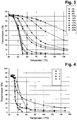
- Fig. 1 the transmission change for the four mixtures is shown as a function of the temperature.
- mixtures 2 and 4 have a homogeneous appearance and no visible light scattering.
- the mixtures 1, 2, 3 and 4 are prepared and polymerized (curing 3 min, 360 nm edge filter, 37 mW / cm 2 ).
- the mixtures are introduced into a switching element according to the invention and constitute therein the switching layer.
- the switching layer is present in the embodiment of a TN cell with a layer thickness of 4 microns.
- the polarizers of the switching element are in a crossed position (90 °).
- the blends have a homogeneous appearance and no visible light scattering.
- the switching element containing mixture 1 represents a switching element of type A (low residual transmission and high sensitivity of the switching operation), while the switching element containing mixture 4 represents a switching element of type B (high residual transmission and low sensitivity of the switching operation).
- the switching elements containing mixture 2 or mixture 3 represent transitional forms.
- the present example thus shows how different transmission curves of the switching elements can be obtained by suitable choice of mono- and diacrylates with different values for the birefringence, corresponding to the types A and B of the switching element according to the invention described above and in the description.
- Each of the monomers is a low birefringence monoacrylate (RM-M2) and a high birefringence diacrylate (RM-D1).
- the mixtures are introduced into a switching element according to the invention and constitute therein the switching layer.
- the switching layer is present in the embodiment of a TN cell with a layer thickness of 4 microns.
- the polarizers of the switching element are in a crossed position (90 °).
- the example shows that, as in example 2, a transition between type A switching elements to type B switching elements can be achieved, this time by increasing the concentration of monomers in the mixture.
- the mixtures are introduced into a switching element according to the invention and constitute therein the switching layer.
- the switching layer is present in the embodiment of a TN cell with a layer thickness of 4 microns.
- the polarizers of the switching element are in a crossed position (90 °).
- the blends have a homogeneous appearance and no visible light scattering.
Landscapes
- Chemical & Material Sciences (AREA)
- Crystallography & Structural Chemistry (AREA)
- Engineering & Computer Science (AREA)
- Materials Engineering (AREA)
- Organic Chemistry (AREA)
- Physics & Mathematics (AREA)
- Nonlinear Science (AREA)
- Optics & Photonics (AREA)
- General Physics & Mathematics (AREA)
- Civil Engineering (AREA)
- Structural Engineering (AREA)
- Liquid Crystal (AREA)
- Polarising Elements (AREA)
- Polymerisation Methods In General (AREA)
- Addition Polymer Or Copolymer, Post-Treatments, Or Chemical Modifications (AREA)
- Liquid Crystal Substances (AREA)
Description
- Die vorliegende Erfindung betrifft ein temperaturgesteuertes Schaltelement zur Regulation des Lichtdurchtritts. Weiterhin betrifft die Erfindung eine Mischung enthaltend mindestens eine flüssigkristalline Verbindung, mindestens eine Monomerverbindung, welche eine monofunktionelle Verbindung darstellt, und mindestens eine Monomerverbindung, welche eine multifunktionelle Verbindung darstellt. Nochmals weiterhin betrifft die Erfindung die Verwendung der genannten Mischung zur Herstellung des erfindungsgemäßen Schaltelements.
- Die Energieeffizienz von Gebäuden gewinnt mit steigenden Energiekosten an Bedeutung. Fenster und Glasfassaden wurden in diesem Zusammenhang als diejenigen Elemente eines Gebäudes identifiziert, durch die der Großteil an Wärmeenergie eines Gebäudes bei niedrigen Außentemperaturen verloren geht, bzw. durch die der Großteil des Energie-Eintrags in ein Gebäude bei intensiver Sonneneinstrahlung stattfindet.
- Es besteht daher Bedarf an Vorrichtungen, welche den Lichtdurchtritt und damit den Energiefluss durch Fenster bzw. Glasflächen kontrollieren. Insbesondere besteht Bedarf an Vorrichtungen, welche den Energiefluss durch Glasflächen an die zum jeweiligen Zeitpunkt vorherrschenden Bedingungen (Hitze, Kälte, hohe Sonneneinstrahlung, niedrige Sonneneinstrahlung) anpassen können.
- Von besonderem Interesse ist die Bereitstellung solcher Vorrichtungen in gemäßigten Klimazonen, in denen über das Jahr ein Wechsel von warmen Außentemperaturen kombiniert mit hoher Sonneneinstrahlung (Sommer) und kalten Außentemperaturen kombiniert mit niedriger Sonneneinstrahlung (Winter) auftritt.
- Beispielsweise ist es in der kalten Jahreszeit erwünscht, dass ein Maximum an Licht und damit transportierter Wärmeenergie durch Glasflächen in ein Gebäude gelangt. Dadurch können Heiz- und Beleuchtungskosten eingespart werden.
- Andererseits ist es in der warmen Jahreszeit erwünscht, dass ein möglichst geringer Energie-Eintrag durch Glasflächen in ein Gebäude erfolgt. Dadurch kann ein angenehmeres Raumklima erreicht werden, bzw. es können Kosten für die Klimatisierung eingespart werden. Weiterhin kann in diesen Fällen eine Herabsetzung der einfallenden Lichtintensität erwünscht sein, beispielsweise um Blendung durch direkte Sonneneinstrahlung zu verringern.
- Es besteht daher Bedarf an Schaltelementen, welche den Lichtdurchtritt durch Fenster oder sonstige Glasflächen regulieren. Insbesondere besteht Bedarf an Schaltelementen, welche die Regulation des Lichtdurchtritts automatisch an die vorherrschenden Bedingungen, wie oben dargestellt, anpassen (smart windows). Weiterhin besteht Bedarf an Schaltelementen, welche energieeffizient arbeiten, mit möglichst geringem technischem Aufwand installierbar sind, technisch zuverlässig sind und ästhetischen Ansprüchen genügen. Weitere Aspekte sind eine leichte Verarbeitbarkeit des Schaltelements, Robustheit im Betrieb und Nachrüstbarkeit an bestehenden Glasflächen von Gebäuden.
- Im Stand der Technik bekannt sind Vorrichtungen, die bei Anlegen einer elektrischen Spannung reversibel von einem transparenten Zustand hin zu einem weniger lichtdurchlässigen, beispielsweise einem trüben (lichtstreuenden) oder einem dunkel-transparenten Zustand geschaltet werden können (z. B. C. M. Lampert et al., Solar Energy Materials & Solar Cells, 2003, 489-499).
- Elektrisch schaltbare Vorrichtungen wie die oben genannten Vorrichtungen weisen jedoch den Nachteil auf, dass sie sich nicht unmittelbar und automatisch an die Umgebungsbedingungen anpassen können. Weiterhin benötigen sie elektrische Anschlüsse, was einen erhöhten Aufwand bei der Installation sowie einen erhöhten Wartungsbedarf mit sich bringt.
- In
US 2009/0015902 undUS 2009/0167971 werden temperatur-reaktive Vorrichtungen offenbart, die ein flüssigkristallines Medium in einer Schicht zwischen zwei Polarisatoren enthalten. Dabei wird das Schalten zwischen einem Zustand mit höherer Lichttransmission und einem Zustand mit geringerer Lichttransmission durch einen Phasenübergang des flüssigkristallinen Mediums von einem nematischen Zustand zu einem isotropen Zustand erreicht, ohne dass das Anlegen einer Spannung notwendig wird. - Die in den genannten Anmeldungen offenbarten Vorrichtungen weisen jedoch den Nachteil auf, dass die Schicht enthaltend das flüssigkristalline Medium flüssig ist. Die Vorrichtung ist daher anfälliger gegenüber Beschädigungen.
- Weiterhin wäre es wünschenswert, flexible Schaltelemente zur Verfügung zu haben, welche wie Folien aufgerollt und geschnitten werden können. Dies ist jedoch bei Vorrichtungen enthaltend eine flüssige Schicht weniger gut möglich, da es in diesen Fällen zu einem Herausdrücken der Flüssigkeit und zu einer Bildung von Luftblasen in der flüssigen Schicht kommen kann.
- Nochmals weiterhin wäre es wünschenswert, die Resttransmission der Vorrichtung im geschlossenen Zustand sowie ihre Schalteigenschaften variieren zu können.
- Flüssigkristalline Medien enthaltend polymere Verbindungen sind im Stand der Technik bekannt. Beispielsweise offenbart Appl. Phys. Lett. 84, 1233 Mischungen enthaltend flüssigkristalline Verbindungen sowie Polymere (polymer network liquid crystal, PDLC) zur Verwendung in elektrisch angesteuerten Lichtmodulatoren. Solche Mischungen weisen jedoch in vielen Fällen den Nachteil auf, trüb bzw. lichtstreuend zu sein.
-
US2011/234944 offenbart die Merkmale des bezeichnenden Teils des Anspruchs 1. - Gegenstand der vorliegenden Erfindung ist ein temperaturgesteuertes Schaltelement zur Regulation des Lichtdurchtritts gemäß des unabhängigen Anspruchs 1. Unter dem Begriff Licht wird im Rahmen der vorliegenden Erfindung elektromagnetische Strahlung im UV-A-, VIS-, sowie NIR-Bereich verstanden. Insbesondere wird darunter Strahlung verstanden, welche von den üblicherweise in Fenstern verwendeten Materialien (z. B. Glas) nicht oder nur in einem vernachlässigbaren Umfang absorbiert wird.
- Gemäß den üblicherweise auf dem Gebiet der Strahlungsphysik verwendeten Definitionen wird unter UV-A-Licht Strahlung einer Wellenlänge von 320 bis 380 nm verstanden, unter VIS-Licht Strahlung einer Wellenlänge von 380 nm bis 780 nm verstanden und unter NIR-Licht Strahlung einer Wellenlänge von 780 nm bis 3000 nm verstanden. Unter dem Begriff Licht wird im Rahmen der vorliegenden Erfindung daher Strahlung einer Wellenlänge von 320 bis 3000 nm verstanden.
- Unter dem Begriff Schaltelement zur Regulation des Lichtdurchtritts wird im Rahmen der vorliegenden Erfindung eine Vorrichtung verstanden, welche eine definierte Fläche bedeckt und die Transmission von Licht durch diese Fläche, abhängig von dem Schaltzustand, in dem die Vorrichtung vorliegt, unterschiedlich stark reduziert.
- Unter dem Begriff flüssigkristalline Verbindung wird eine Verbindung verstanden, welche unter bestimmten Bedingungen flüssigkristalline Eigenschaften zeigt, und insbesondere eine Verbindung, welche unter bestimmten Bedingungen eine nematische flüssigkristalline Phase ausbildet.
- Unter einer mesogenen Gruppe wird im Rahmen der vorliegenden Erfindung ein Strukturelement verstanden, welches bereits für sich alleine, d. h. auch ohne Zusammenwirken mit einer weiteren Gruppe wie einer Abstandsgruppe oder einer reaktiven Gruppe (vgl. Offenbarung zu Monomerverbindungen unten) flüssigkristalline Eigenschaften der Verbindung bewirkt. Mesogene Gruppen sind typischerweise solche chemischen Gruppen oder Einheiten, wie sie auch bei niedermolekularen, nicht reaktiven flüssigkristallinen Verbindungen vorkommen. Beispiele sind u. a. Biscyclohexyle, Phenylcyclohexyle, Biphenyle und Phenylbenzoate.
- Die mesogene Gruppe ist erfindungsgemäß in mindestens einer Wiederholeinheit des Polymers enthalten. Sie kann in einer Seitenkette und/oder in der Hauptkette des Polymers enthalten sein. Bevorzugt ist sie in der Seitenkette enthalten.
- Unter einer Wiederholeinheit wird eine Einheit des Polymers verstanden, welche mehrfach, mindestens zweimal, im Polymer vorkommt. Bevorzugt entspricht die Zahl ihres Auftretens im Polymer dem Anteil von Monomer enthaltend die Wiederholeinheit an den zur Polymerisation eingesetzten Monomeren.
- Bevorzugt enthalten mindestens 10 % der Wiederholeinheiten des Polymers eine oder mehrere mesogene Gruppen, besonders bevorzugt mindestens 30 %, ganz besonders bevorzugt mindestens 60 % und noch stärker bevorzugt mindestens 90 %. Am stärksten bevorzugt enthalten im wesentlichen alle Wiederholeinheiten des Polymers eine oder mehrere mesogene Gruppen.
- Als die beiden Schaltzustände des Schaltelements liegen erfindungsgemäß ein Schaltzustand mit höherer Lichttransmission durch das Schaltelement (Schaltzustand I oder offener Zustand) und ein Schaltzustand mit geringerer Lichttransmission durch das Schaltelement (Schaltzustand II oder geschlossener Zustand) vor.
- Der Unterschied in der Lichttransmission zwischen den beiden Zuständen wird gemäß der vorliegenden Anmeldung als der Schalthub der Vorrichtung bezeichnet.
- Das Schaltelement ist gemäß der Erfindung temperaturgesteuert, worunter verstanden wird, dass der Schaltvorgang durch eine Änderung der Temperatur der Vorrichtung bewirkt werden kann. Die zwei Schaltzustände der Vorrichtung sind folglich mit zwei unterschiedlichen Temperaturbereichen der Vorrichtung verbunden. Die Temperatursteuerung des Schaltelements findet erfindungsgemäß in einem Temperaturbereich zwischen 0 °C und 80 °C, bevorzugt zwischen 10 °C und 70 °C und ganz besonders bevorzugt zwischen 20 °C und 60 °C statt.
- Gemäß einer bevorzugten Ausführungsform der Erfindung liegt der Schaltzustand mit höherer Lichttransmission durch das Schaltelement bei niedrigeren Temperaturen des Schaltelements vor, und der Schaltzustand mit geringerer Lichttransmission liegt bei höheren Temperaturen des Schaltelements vor.
- Die Funktionsweise des Schaltelements beruht darauf, dass einfallendes Licht durch den ersten Polarisator polarisiert wird. Dies bedeutet, dass nur Licht mit bestimmten Polarisationseigenschaften durch den Polarisator hindurchgelassen wird. Die polarisationsbeeinflussende Schaltschicht verändert in einem der beiden Schaltzustände die Polarisationseigenschaften des polarisierten Lichts, welches den ersten Polarisator verlässt und in die Schaltschicht gelangt. Dadurch kann ein höherer oder ein niedrigerer Anteil des polarisierten Lichts durch den zweiten Polarisator hindurchtreten, je nachdem wie dessen Polarisationsebene relativ zu der des ersten Polarisators angeordnet ist. Im anderen der beiden Schaltzustände verändert die polarisationsbeeinflussende Schaltschicht die Polarisationseigenschaften des durch sie hindurchtretenden Lichts nicht oder nur in geringem Umfang.
- Dies soll an einem Beispiel verdeutlicht werden: sind die beiden Polarisationsebenen der Polarisatoren um einen Winkel x gegeneinander gedreht und dreht im ersten Schaltzustand des Schaltelements die Schaltschicht die Polarisationsebene ebenfalls um einen Winkel x, so tritt ein Großteil des Lichts, welches durch den ersten Polarisator gelangt ist, auch durch den zweiten Polarisator und damit durch das gesamte Schaltelement hindurch. Im anderen der beiden Schaltzustände der Schaltschicht wird die Polarisationsebene des Lichts durch die Schaltschicht nicht gedreht oder nur geringfügig gedreht, so dass aufgrund der Drehung der Polarisationsebenen der beiden Polarisatoren gegeneinander nur ein geringer Teil des Lichts, welches durch den ersten Polarisator hindurchtritt, durch den zweiten Polarisator hindurchgelassen wird. Es tritt somit in diesem Zustand des Schaltelements nur ein geringer Teil des Lichts, welches auf das Schaltelement trifft, durch dieses hindurch. In diesem Beispiel ist der polarisationsbeeinflussende Zustand der Schaltschicht somit mit Schaltzustand I verbunden, und der die Polarisation nicht beeinflussende, inaktive Zustand ist mit Schaltzustand II verbunden.
- In allen Fällen gilt jedoch, dass der Zustand der Schaltschicht (polarisationsbeeinflussend oder inaktiv) den Zustand des Schaltelements (Schaltzustand I oder Schaltzustand II) bestimmt. Erfindungsgemäß ist der polarisationsbeeinflussende Zustand der Schaltschicht mit einem flüssigkristallinen, optisch anisotropen Zustand der Schicht verbunden, und der inaktive Zustand der Schaltschicht ist mit einem isotropen Zustand der Schicht verbunden. Hierbei kann jedoch eine Rest-Anisotropie der Schaltschicht bedingt durch anisotropes Polymer verbleiben.
- Allgemein wird unter einem isotropen Zustand der Schaltschicht ein Zustand weitgehender Isotropie verstanden. Es ist dabei nicht ausgeschlossen, dass eine Rest-Anisotropie auch im als isotrop bezeichneten Zustand vorhanden ist. Dies kann beispielsweise durch das Polymer verursacht sein, welches in beiden Zuständen der Vorrichtung zumindest zum Teil anisotrope Eigenschaften aufweist.
- Gemäß einer bevorzugten Ausführungsform liegt die Schaltschicht im Schaltzustand I des Schaltelements im polarisationsbeeinflussenden Zustand vor und im Schaltzustand II im inaktiven Zustand vor. Erfindungsgemäß verläuft der Schaltvorgang zwischen den beiden Schaltzuständen nicht abrupt bei einer bestimmten Temperatur, welche die beiden oben genannten Temperaturbereiche trennt, sondern graduell in einem Übergangsbereich, welcher in einer Temperaturspanne liegt. Diese Temperaturspanne des Übergangsbereichs weist bevorzugt eine Breite von 5 bis 100 Graden Celsius auf, verläuft also beispielweise zwischen 15 und 110 °C. Besonders bevorzugt weist die Temperaturspanne eine Breite von 10 bis 50 Graden Celsius auf.
- Als Übergangsbereich zwischen den beiden Schaltzuständen wird im Rahmen der vorliegenden Anmeldung jener Temperaturbereich verstanden, in dem weniger als das 0.8-fache der Transmission des Schaltzustands mit der höheren Lichttransmission und mehr als das 1.2-fache der Transmission des Schaltzustands mit der niedrigeren Lichttransmission vorliegen.
- Es ist für den Fachmann offensichtlich, dass mit einem ausgedehnteren Übergangsbereich des Schaltvorgangs eine geringere Empfindlichkeit des Schaltens gegenüber einer Temperaturänderung verbunden ist, und umgekehrt mit einem engen Übergangsbereich des Schaltvorgangs eine höhere Empfindlichkeit des Schaltvorgangs gegenüber einer Temperaturänderung verbunden ist.
- Anstelle einer Beschreibung der oben genannten Empfindlichkeit des Schaltvorgangs durch die Breite des Übergangsbereichs kann alternativ und für den Fachmann austauschbar auch eine Beschreibung über die relative Steigung der Kurve einer Auftragung von Transmission (y-Achse) gegen Temperatur (x-Achse) erfolgen. In diesem Fall ist mit einer betragsgroßen Steigung der Kurve eine hohe Empfindlichkeit des Schaltvorgangs verbunden, und mit einer betragskleinen Steigung der Kurve eine niedrige Empfindlichkeit des Schaltvorgangs verbunden.
- Gemäß einer möglichen Ausführungsform der Erfindung weist die Temperaturspanne des Übergangsbereichs zwischen den beiden Schaltzuständen eine Breite von 5 bis 30 Graden Celsius auf, besonders bevorzugt eine Breite von 10 bis 20 Graden Celsius (Schaltelement Typ A' mit hoher Empfindlichkeit des Schaltvorgangs).
- Eine solche Ausführungsform ist bevorzugt, wenn der Schaltvorgang in einem möglichst engen Temperaturbereich stattfinden soll (hohe Empfindlichkeit des Schaltvorgangs, vgl. oben). Dies kann erfindungsgemäß erreicht werden beispielsweise durch die Verwendung eines geringen Anteils an Polymer in der Schaltschicht oder durch die Verwendung geeigneter Arten von Monomeren in der Polymerisationsreaktion zum Polymer. Explizite Ausgestaltungen für diese Ausführungsform werden in einem folgenden Abschnitt beschrieben.
- Gemäß einer alternativen Ausführungsform der Erfindung weist die Temperaturspanne des Übergangsbereichs zwischen den beiden Schaltzuständen eine Breite von 30 bis 100 Graden Celsius auf, besonders bevorzugt eine Breite von 50 bis 80 Graden Celsius (Schaltelement Typ B' mit geringer Empfindlichkeit des Schaltvorgangs). Eine solche Ausführungsform ist bevorzugt, wenn der Schaltvorgang über einen ausgedehnten Temperaturbereich stattfinden soll (niedrige Empfindlichkeit des Schaltvorgangs, vgl. oben). Dies kann erfindungsgemäß erreicht werden beispielsweise durch die Verwendung eines höheren Anteils an Polymer in der Schaltschicht oder durch die Verwendung geeigneter Arten von Monomeren in der Polymerisationsreaktion zum Polymer. Explizite Ausgestaltungen für diese Ausführungsform werden in einem folgenden Abschnitt beschrieben.
- Gemäß einer möglichen Ausführungsform der Erfindung weist der Schaltzustand mit geringerer Lichtdurchlässigkeit eine Transmission im VIS-Bereich von mehr als 5 %, bevorzugt von mehr als 10 %, besonders bevorzugt von mehr als 15 % und ganz besonders bevorzugt von mehr als 25 % auf, wobei diese Transmission durch die polarisationsbeeinflussende Schaltschicht bewirkt wird (Schaltelement Typ B" mit hoher Resttransmission).
- Eine solche Ausführungsform des Schaltelements mit einer beträchtlichen Transmission auch im Schaltzustand mit geringerer Lichtdurchlässigkeit kann bevorzugt sein in Verwendungsarten, in denen eine völlige Sperrung des Lichtdurchtritts in keinem Fall eintreten soll. Dies ist beispielsweise denkbar bei der Verwendung des Schaltelements in einem Fenster eines Büro- oder eines Wohngebäudes.
- An dieser Stelle soll hervorgehoben werden, dass die oben genannte Lichttransmission im Schaltzustand mit geringerer Lichtdurchlässigkeit in Vorrichtungen wie den erfindungsgemäßen Schaltelementen prinzipiell auch durch die Anordnung der Polarisatoren zueinander beeinflusst werden kann. Möglichkeiten hierzu sind dem Fachmann geläufig. Beispielsweise kann eine erhöhte Lichttransmission im Schaltzustand mit geringerer Lichtdurchlässigkeit durch eine Anordnung, in der die Polarisationsrichtungen der Polarisatoren um einem von 90° abweichenden Winkel gegeneinander gedreht sind, erreicht werden.
- Wie obenstehend explizit erwähnt wurde, wird die Transmission von mehr als 5 %, bevorzugt mehr als 10 % und besonders bevorzugt mehr als 25 % in der oben genannten erfindungsgemäßen Ausführungsform jedoch durch die Schaltschicht bewirkt und nicht durch die Stellung der Polarisatoren zueinander.
- Dies kann erfindungsgemäß erreicht werden beispielsweise durch die Verwendung von Monomeren mit hohen Werten für die Doppelbrechung Δn in der Polymerisation zum Polymer, insbesondere durch die Verwendung von hohen Anteilen solcher Monomere und/oder durch einen hohen Anteil von Polymer insgesamt in der Mischung von Polymer und flüssigkristalliner Verbindung in der Schaltschicht.
- Gemäß einer alternativen bevorzugten Ausführungsform der Erfindung weist der Schaltzustand mit geringerer Lichtdurchlässigkeit eine Transmission im VIS-Bereich von höchstens 5 %, bevorzugt von höchstens 4 % und besonders bevorzugt von höchstens 3 % auf (Schaltelement Typ A" mit geringer Resttransmission).
- Dies kann erfindungsgemäß erreicht werden durch die Verwendung von Monomeren mit niedrigen Werten für die Doppelbrechung Δn in der Polymerisation zum Polymer, insbesondere durch die Verwendung von niedrigen Anteilen solcher Monomere und/oder durch einen niedrigen Anteil von Polymer insgesamt in der Mischung von Polymer und flüssigkristalliner Verbindung in der Schaltschicht.
- Gemäß einer alternativen besonders bevorzugten Ausführungsform treten die Ausführungsformen A' (Schaltelement mit hoher Empfindlichkeit des Schaltvorgangs) und A" (Schaltelement mit geringer Resttransmission) kombiniert in einem erfindungsgemäßen Schaltelement auf. Ein solches besonders bevorzugtes Schaltelement mit den oben genannten Eigenschaften wird als Schaltelement des Typs A bezeichnet.
- Gemäß einer besonders bevorzugten Ausführungsform treten die Ausführungsformen B' (Schaltelement mit geringer Empfindlichkeit des Schaltvorgangs) und B" (Schaltelement mit hoher Resttransmission) kombiniert in einem erfindungsgemäßen Schaltelement auf. Ein solches besonders bevorzugtes Schaltelement mit den oben genannten Eigenschaften wird als Schaltelement des Typs B bezeichnet.
- Erfindungsgemäß wurde gefunden, dass durch Einstellung bestimmter Parameter betreffend die Konzentration der für die Polymerisationsreaktion zum Polymer verwendeten Monomere, deren Doppelbrechung Δn sowie deren Zahl von reaktiven funktionellen Gruppen (monofunktionelle vs. multifunktionelle Monomere) nach Wahl entweder Schaltelemente des Typs A oder des Typs B erhalten werden können. Auf diese Aspekte wird in einem folgenden Abschnitt näher eingegangen.
- Das erfindungsgemäße Schaltelement ist bevorzugt dadurch gekennzeichnet, dass es keine Vorrichtungen zur elektrischen Ansteuerung des Schaltvorgangs enthält. Besonders bevorzugt enthält es keinerlei Vorrichtungen zur elektrischen Ansteuerung wie beispielsweise Drähte, Kabel, elektrische Anschlüsse oder Schaltkreise.
- Das erfindungsgemäße Schaltelement ist bevorzugt in einer beliebigen baulichen Öffnung eines Gebäudes oder eines sonstigen weitgehend nach außen abgeschlossenen Kompartiments angebracht.
- Besonders bevorzugt ist das Schaltelement in einer baulichen Öffnung in einer Seitenwand oder Decke eines Gebäudes angebracht.
- Prinzipiell sind jedoch alle Arten von Öffnungen in einem weitgehend nach außen abgeschlossenen Kompartiment zur Anbringung des Schaltelements geeignet, sofern sie Lichtdurchlässigkeit aufweisen.
- Unter einem weitgehend nach außen abgeschlossenen Kompartiment werden im Rahmen der vorliegenden Anmeldung insbesondere ein Gebäude oder einzelne Räume eines Gebäudes verstanden. Das Gebäude kann dabei unter anderem ein privates Gebäude, beispielsweise ein Wohnhaus sein, oder es kann ein öffentliches Gebäude oder ein gewerblich genutztes Gebäude wie beispielsweise ein Fabrikgebäude, eine Lagerhalle oder ein Bürogebäude sein. Das Kompartiment kann gemäß einer alternativen Ausführungsform aber auch ein Fahrzeug, beispielsweise ein Auto oder ein Lastkraftwagen, oder ein Container, beispielsweise ein Transportcontainer sein.
- Bevorzugt sind bauliche Öffnungen wie Fenster oder Decken einer Größe von mehr als 0.5 m2, besonders bevorzugt mehr als 1 m2, ganz besonders bevorzugt mehr als 3 m2. Dies ist dadurch bedingt, dass durch solche Flächen, wenn sie von der Sonne bestrahlt werden, eine hohe Energieaufnahme in den Innenraum erfolgt, sofern keine geeigneten Maßnahmen getroffen werden, um die Lichttransmission und damit die Energieaufnahme in den Innenraum zu verringern. Bevorzugt sind weiterhin bauliche Öffnungen, die aufgrund ihrer räumlichen Ausrichtung und/oder der geographischen und klimatischen Lage des Gebäudes einer hohen Sonneneinstrahlung ausgesetzt sind.
- Das Schaltelement ist bevorzugt flächendeckend auf der baulichen Öffnung angeordnet, so dass die Lichttransmission durch die Öffnung möglichst vollständig reguliert werden kann. In einer möglichen Ausführungsform erfolgt die Abdeckung durch ein einziges Schaltelement. In einer alternativen Ausführungsform kann die Abdeckung aber auch durch mehrere Schaltelemente erfolgen, die entweder unmittelbar aneinander angrenzen oder unter Lückenlassung angeordnet sind.
- In vielen Fällen wird die bauliche Öffnung mit einem durchsichtigen Material abgedeckt sein, beispielsweise durch eine Glasscheibe oder eine Plexiglasscheibe. Gemäß einer bevorzugten Ausführungsform wird das erfindungsgemäße Schaltelement direkt auf dieser Scheibe aufgebracht.
- Eine solche Aufbringung kann durch Nachrüsten einer bereits bestehenden Anordnung oder durch kompletten Neueinbau erfolgen.
- Eine unter dem Gesichtspunkt der Wärmedämmung vorteilhafte Ausführungsform der Abdeckung einer baulichen Öffnung ist eine Anordnung enthaltend zwei oder mehr Glasscheiben, wobei der Zwischenraum zwischen den Glasscheiben mit Luft oder mit einer speziellen Gasmischung gefüllt ist (Mehrscheiben-Isolierglas). Entsprechend ist es erfindungsgemäß bevorzugt, das Schaltelement im Inneren einer solchen Mehrscheiben-Isolierglasscheibe anzubringen oder außen an eine solche Scheibe anzubringen.
- Allgemein bevorzugt ist die Verwendung auf einer zum Innenraum hin gerichteten Seite einer Scheibe oder im Zwischenraum zwischen zwei Glasscheiben bei Mehrscheiben-Isolierglas. Es sind jedoch auch andere Anordnungen denkbar und in bestimmten Fällen vorzuziehen. Der Fachmann kann Vor- und Nachteile bestimmter Anordnungen bezüglich der Haltbarkeit des Schaltelements, optischen und ästhetischen Gesichtspunkten, praktischen Gesichtspunkten bezüglich der Reinigung der Scheiben sowie bezüglich der Reaktivität des Schaltelements gegenüber Temperaturänderungen des Innenraums und der äußeren Umgebung gegeneinander abwägen und eine für den vorliegenden Fall optimale Ausgestaltungsform auswählen.
- Gemäß einer bevorzugten Ausführungsform ist das Schaltelement dadurch gekennzeichnet, dass es eine Flächenausdehnung von mindestens 0.05 m2, bevorzugt von 0.1 m2 bis 20 m2 und besonders bevorzugt von 0.2 m2 bis 5 m2 aufweist.
- Gemäß einer bevorzugten Ausführungsform wird das Schaltelement zur temperaturabhängigen Beeinflussung der Lichttransmission verwendet, besonders bevorzugt zur Beeinflussung der Lichttransmission ausgehend von der Sonne in einen Innenraum.
- Bei der erfindungsgemäßen Verwendung sind die oben genannten sowie auch die in folgenden Teilen aufgeführten bevorzugten Ausführungsformen des Schaltelements ebenfalls bevorzugt.
- Die Lichttransmission von der Umgebung in einen Innenraum bedeutet einen Energieeintrag in den Innenraum, welcher aufgrund allgemeiner physikalischer Gesetze zu einer Temperaturerhöhung des Innenraums führt. Die Beeinflussung der Lichttransmission durch das erfindungsgemäße Schaltelement bedeutet somit nicht nur, dass der Lichteintrag, unter anderem in Form von VIS-Licht, in einen Innenraum reguliert werden kann, sondern auch, dass der Wärmeeintrag und damit die Temperatur des Innenraums reguliert werden kann. Die Verwendung des Schaltelements zu diesem Zweck ist ebenfalls Gegenstand der vorliegenden Erfindung.
- Aufgrund der weiter oben beschriebenen Temperaturabhängigkeit des Schaltelements, wobei gemäß einer bevorzugten Ausführungsform der offene Schaltzustand bei einer niedrigeren Temperatur und der geschlossene Schaltzustand bei einer höheren Temperatur vorliegt, kann somit eine Selbstregulation der Temperatur des Innenraums erfolgen. Dabei wird bei einer niedrigen Temperatur die Lichttransmission und damit der Wärmeeintrag erhöht, so dass die Innenraumtemperatur ansteigt. Entsprechend wird bei einer höheren Temperatur die Lichttransmission und damit der Wärmeeintrag verringert, so dass die Innenraumtemperatur absinkt.
- Das Schalten zwischen den beiden Schaltzuständen erfolgt temperaturreguliert. Gemäß einer bevorzugten Ausführungsform wird das Schaltelement rein temperaturreguliert verwendet, ohne dass die Schaltschicht durch das Anlegen eines elektrischen Feldes beeinflusst wird.
- Wie dem Fachmann bekannt ist, kann die polarisationsbeeinflussende Schaltschicht, welche unter anderem mindestens eine flüssigkristalline Verbindung enthält, unter bestimmten Bedingungen durch das Anlegen eines elektrischen Feldes von einem Schaltzustand in einen anderen Schaltzustand gebracht werden. Ein solche elektrisch bewirkte Beeinflussung der Schaltschicht und somit des gesamten Schaltelements kann unter bestimmten Bedingungen bevorzugt sein, beispielsweise um einen ursprünglichen Zustand der Schaltschicht nach einer größeren Zahl von Schaltvorgängen wiederherzustellen. Es ist jedoch festzuhalten, dass es ein Merkmal der Erfindung ist, dass das Schaltelement für den regulären Gebrauch rein temperaturgesteuert verwendet wird, und dass die erfindungsgemäße Verwendung des Schaltelements kein Anlegen eines elektrischen Feldes erfordert.
- Weiterhin ist eine Verwendung des Schaltelements bevorzugt, bei der die Lichttransmission unter anderem im NIR-Bereich beeinflusst wird. Strahlung im NIR-Bereich trägt zu einem großen Anteil zum Eintrag von Energie in Innenräume durch Fenster bei. Besonders bevorzugt ist aufgrund der erfindungsgemäßen Ausgestaltung der Vorrichtung, insbesondere in den bevorzugten Ausführungsformen, eine Beeinflussung der Lichttransmission im Bereich von 1000 bis 1500 nm Wellenlänge.
- In einer bevorzugten Ausführungsform der Erfindung ist die polarisationsbeeinflussende Schaltschicht des Schaltelements zwischen zwei Substratschichten angeordnet.
- Die Substratschichten können erfindungsgemäß unter anderem aus polymerem Material, aus Metalloxid, beispielsweise ITO, aus Glas oder aus Metall bestehen. Bevorzugt bestehen sie aus Glas oder ITO oder polymerem Material.
- Das erfindungsgemäße Schaltelement kann zusätzlich zu den oben angegebenen Komponenten noch weitere Elemente umfassen, beispielsweise eine oder mehrere Orientierungsschichten. Besonders bevorzugt sind genau zwei Orientierungsschichten vorhanden. Diese sind bevorzugt jeweils zwischen der Substratschicht und der Schaltschicht angeordnet. Die Orientierungsschichten können auch als Substratschichten dienen, so dass keine Substratschichten in der Vorrichtung erforderlich sind. In einer bevorzugten Ausführungsform der Erfindung bestehen die Orientierungsschichten aus geriebenem Polyimid oder geriebenem Polyacrylat.
- Es ist gemäß der vorliegenden Erfindung jedoch ebenfalls möglich und unter bestimmten Bedingungen vorteilhaft, dass das Schaltelement keine Orientierungsschicht angrenzend an die Schaltschicht enthält.
- Weiterhin ist es bevorzugt, dass das erfindungsgemäße Schaltelement eine oder mehrere Filterschichten enthält, bevorzugt eine oder mehrere UV-Filterschichten. Besonders bevorzugt enthält das Schaltelement einen UV-Filter, welcher Licht mit einer Wellenlänge von weniger als 300 nm, bevorzugt Licht mit einer Wellenlänge von weniger als 320 nm, besonders bevorzugt Licht mit einer Wellenlänge von weniger als 340 nm und ganz besonders bevorzugt Licht mit einer Wellenlänge von weniger als 360 nm blockiert.
- Erfindungsgemäß weist das Schaltelement zwei oder mehr Polarisatoren auf, von denen einer an der einen Seite der Schaltschicht und ein anderer an der gegenüberliegenden Seite der Schaltschicht angeordnet ist. Dabei sind Schaltschicht und die beiden Polarisatoren bevorzugt parallel zueinander angeordnet.
- Die Polarisatoren können Linearpolarisatoren oder Zirkularpolarisatoren darstellen. Bevorzugt sind genau zwei Polarisatoren in der Vorrichtung vorhanden. In diesem Fall ist es weiterhin bevorzugt, dass die Polarisatoren entweder beide Linearpolarisatoren oder beide Zirkularpolarisatoren darstellen.
- Sind zwei lineare Polarisatoren in der Vorrichtung vorhanden, so ist es erfindungsgemäß bevorzugt, dass die Polarisationsrichtungen der beiden Polarisatoren um einen Winkel von 45° bis 135°, besonders bevorzugt 70° bis 110° und ganz besonders bevorzugt 80° bis 100° gegeneinander gedreht sind.
- Die Polarisatoren können reflektive oder absorptive Polarisatoren darstellen. Ein reflektiver Polarisator im Sinne der vorliegenden Anmeldung reflektiert Licht einer Polarisationsrichtung bzw. einer Art von circular polarisiertem Licht, während er für Licht der anderen Polarisationsrichtung bzw. der anderen Art von circular polarisiertem Licht durchlässig ist. Entsprechend absorbiert ein absorptiver Polarisator Licht einer Polarisationsrichtung bzw. einer Art von circular polarisiertem Licht, während er für Licht der anderen Polarisationsrichtung bzw. der anderen Art von circular polarisiertem Licht durchlässig ist.
- Im Rahmen der vorliegenden Erfindung können sowohl absorptive als auch reflektive Polarisatoren eingesetzt werden. Bevorzugt werden Polarisatoren verwendet, die als dünne optische Filme vorliegen. Beispiele für reflektive Polarisatoren, die in der erfindungsgemäßen Vorrichtung verwendet werden können, sind DRPF- (diffusive reflective polariser film, 3M), DBEF- (dual brightness enhanced film, 3M), DBR- (layered-polymer distributed Bragg reflectors, wie in
US 7,038,745 undUS 6,099,758 beschrieben) und APF-Filme (advanced polariser film, 3M, vgl. Technical Digest SID 2006, 45.1,US 2011/0043732 undUS 7023602 ). Weiterhin können Polarisatoren basierend auf Drahtgittern (WGP, wire-gridpolarisers), welche Infrarotlicht reflektieren, eingesetzt werden. Beispiele für absorptive Polarisatoren, welche in den erfindungsgemäßen Vorrichtungen eingesetzt werden können, sind der Itos XP38-Polarisatorfilm und der Nitto Denko GU-1220DUN-Polarisatorfilm. Ein Beispiel für einen circularen Polarisator, welcher erfindungsgemäß verwendet werden kann, ist der Polarisator APNCP37-035-STD (American Polarizers). Ein weiteres Beispiel ist der Polarisator CP42 (ITOS). - Polarisatoren sind typischerweise nicht im gesamten Spektrum des UV-A, VIS- und NIR-Bereichs gleichermaßen wirksam. Gemäß einer bevorzugten Ausführungsform enthält das erfindungsgemäße Schaltelement Polarisatoren, welche Licht unter anderem im NIR-Bereich polarisieren. Gemäß einer bevorzugten Ausführungsform der Erfindung stellen der erste und der zweite Polarisator jeweils gleich oder verschieden einen absorptiven oder einen reflektiven Linearpolarisator dar. Besonders bevorzugt stellen entweder beide Polarisatoren einen absorptiven Linearpolarisator dar, oder beide Polarisatoren stellen einen reflektiven Linearpolarisator dar. Gemäß einer weiteren bevorzugten Ausführungsform ist der nach außen, d. h. vom Innenraum weg gerichtete Polarisator ein reflektiver Polarisator.
- In einer möglichen erfindungsgemäßen Ausführungsform stellen die beiden Polarisatoren die Substratschichten dar, zwischen denen die Schaltschicht angeordnet ist, das heißt, es sind keine zusätzlichen Substratschichten in der Vorrichtung vorhanden.
- In einer weiteren bevorzugten Ausführungsform der Erfindung befindet sich die Schaltschicht zwischen flexiblen Schichten, beispielsweise flexiblen Polymerfolien. Die erfindungsgemäße Vorrichtung ist dadurch formflexibel und biegsam und kann beispielsweise aufgerollt werden. Die flexiblen Schichten können wahlweise Substratschicht, Orientierungsschicht und/oder Polarisatoren darstellen. Weitere Schichten, welche bevorzugt ebenfalls flexibel sind, können zusätzlich vorhanden sein.
- Weiterhin hat die Schaltschicht erfindungsgemäß eine gelartige oder zumindest zähflüssige Konsistenz. Dies hat den Vorteil einer höheren Robustheit der Vorrichtung. Weiterhin kann die erfindungsgemäße Vorrichtung enthaltend eine gel-artige Schaltschicht schneidbar sein, was einen Vorteil bei der Handhabung darstellt.
- Obenstehend wurde angegeben, dass der Zustand der Schaltschicht entscheidet, ob das Schaltelement im offenen Zustand (Schaltzustand I) oder im geschlossenen Zustand (Schaltzustand II) vorliegt.
- Gemäß einer bevorzugten Ausführungsform hat die Schaltschicht im Schaltzustand mit höherer Lichttransmission die Eigenschaft, die Polarisationsebene von linear polarisiertem Licht zu drehen. Gemäß einer bevorzugten Ausführungsform dreht die Schaltschicht in diesem Schaltzustand die Polarisationsebene um einen Betrag von 70 bis 110°, bevorzugt um einen Betrag von 80 bis 100° und besonders bevorzugt um einen Betrag von 85 bis 95°. Entsprechend hat die Schaltschicht im Schaltzustand mit geringerer Lichttransmission die Eigenschaft, die Polarisationsebene von linear polarisiertem Licht nicht oder nur geringfügig zu drehen.
- Es kann jedoch erfindungsgemäß auch eine Ausführungsform der Schaltschicht vorliegen, bei der im verdrillt nematischen Zustand der Vorrichtung eine Drehung der Polarisationsebene des Lichts von mehr als 360° vorliegt, d. h. mehrere vollständige Drehungen der Polarisationsebene erfolgen.
- Besonders bevorzugt ist der Zustand der Schaltschicht im Schaltzustand mit höherer Lichtdurchlässigkeit (Schaltzustand I) ein verdrillt nematischer Zustand. Entsprechend ist der Zustand der Schaltschicht im Schaltzustand mit geringerer Lichtdurchlässigkeit (Schaltzustand II) ein isotroper Zustand. Eine Rest-Anisotropie ist im isotropen Zustand nicht ausgeschlossen.
- Die Schaltschicht umfasst erfindungsgemäß mindestens eine flüssigkristalline Verbindung sowie mindestens ein Polymer, wobei das Polymer mindestens eine Wiederholeinheit enthaltend eine oder mehrere mesogene Gruppen umfasst.
- Bevorzugt liegt in der Schaltschicht eine Mischung verschiedener flüssigkristalliner Verbindungen vor. Besonders bevorzugt liegen in der Schaltschicht mindestens 5 und höchstens 15 verschiedene flüssigkristalline Verbindungen vor.
- Die flüssigkristallinen Verbindungen können beliebig gewählt sein aus dem Fachmann bekannten flüssigkristallinen Verbindungen. Bevorzugt sind flüssigkristalline Verbindungen mit begrenzter Größe und Molekulargewicht (kleine Moleküle). Besonders bevorzugt ist es, wenn die flüssigkristalline Verbindung ein Molekulargewicht von nicht mehr als 1000 Da, ganz besonders bevorzugt von nicht mehr als 800 Da und am stärksten bevorzugt von nicht mehr als 600 Da aufweist.
- Bevorzugt weist die Mischung der flüssigkristallinen Verbindungen (bzw. im Fall, dass nur eine flüssigkristalline Verbindung verwendet wird, die einzelne flüssigkristalline Verbindung) einen Klärpunkt zwischen -20 °C und 200 °C auf, besonders bevorzugt einen Klärpunkt zwischen 10 °C und 180 °C. Aufgrund der Klärpunkt-verändernden Eigenschaften des in der Schaltschicht enthaltenen Polymers sind insbesondere auch Mischungen bzw. Verbindungen mit hohen Klärpunkten, beispielsweise zwischen 80 °C und 200 °C, bevorzugt 100 °C bis 180 °C und besonders bevorzugt zwischen 120 °C und 160 °C zur Verwendung im erfindungsgemäßen Schaltelement geeignet.
- Bevorzugt entsprechen die flüssigkristallinen Verbindungen der folgenden Formel (F-1)

- R11,R12
- bei jedem Auftreten gleich oder verschieden F, Cl, -CN, -NCS, -SCN, R13-O-CO-, R13-CO-O- oder eine Alkyl- oder Alkoxygruppe mit 1 bis 10 C-Atomen oder eine Alkenyl- oder Alkenyloxygruppe mit 2 bis 10 C-Atomen darstellt, wobei ein oder mehrere Wasserstoffatome in den oben genannten Gruppen durch F oder Cl ersetzt sein können, und eine oder mehrere CH2-Gruppen durch O oder S ersetzt sein können; und
- R13
- bei jedem Auftreten gleich oder verschieden eine Alkylgruppe mit 1 bis 10 C-Atomen darstellt, bei der ein oder mehrere Wasserstoffatome durch F oder Cl ersetzt sein können, und bei der eine oder mehrere CH2-Gruppen durch O oder S ersetzt sein können; und
- X
- bei jedem Auftreten gleich oder verschieden ausgewählt ist aus F, Cl, CN oder einer Alkyl-, Alkoxy- oder Alkylthiogruppe mit 1 bis 10 C-Atomen, wobei ein oder mehrere Wasserstoffatome in den oben genannten Gruppen durch F oder Cl ersetzt sein können, und wobei eine oder mehrere CH2-Gruppen in den oben genannten Gruppen durch O oder S ersetzt sein können; und
- Z11
- bei jedem Auftreten gleich oder verschieden ausgewählt ist aus -CO-O-, -O-CO-, -CF2-CF2-, -CF2-O-, -O-CF2-, -CH2-CH2-, -CH=CH-, -CF=CF-, -CF=CH-, -CH=CF-, -C≡C-, -OCH2-, -CH2O-, und einer Einfachbindung; und
- d
- einen Wert von 0, 1, 2, 3, 4, 5 oder 6 annimmt, bevorzugt 0, 1, 2 oder 3, besonders bevorzugt 1, 2 oder 3.
- Gruppen der Teilformel

- Besonders bevorzugt zur Verwendung als flüssigkristalline Verbindungen sind die in den Anmeldungen
WO 2011/134582 ,WO 2011/144299 ,WO 2011/154077 ,WO 2012/025182 undWO 2012/052100 offenbarten Mischungen von flüssigkristallinen Verbindungen. - Es ist erfindungsgemäß bevorzugt, dass die flüssigkristalline Verbindung oder die Mischung flüssigkristalliner Verbindungen in der Schaltschicht in einem Anteil von mindestens 50 %, bevorzugt mindestens 60 %, besonders bevorzugt mindestens 70 % und ganz besonders bevorzugt mindestens 80 % vorliegt.
- In der Schaltschicht liegt bevorzugt eine Art Polymer vor, d. h. ein Polymer, dass in genau einer Polymerisationsreaktion aus entsprechenden Monomeren enthalten wurde. Eine Ausführungsform, in der mehrere unterschiedliche Polymere in der Schaltschicht verwendet werden, d. h. Polymere, welche in mehreren unterschiedlichen Polymerisationsreaktionen, gegebenenfalls unter Verwendung unterschiedlicher Monomere, erhalten wurden, ist jedoch ebenfalls möglich.
- Es ist erfindungsgemäß bevorzugt, dass das Polymer in der Schaltschicht in einem Anteil von höchstens 50 %, bevorzugt höchstens 40 %, besonders bevorzugt höchstens 30 % und ganz besonders bevorzugt höchstens 20 % vorliegt.
- Weiterhin bevorzugt liegen in der Schaltschicht die flüssigkristalline Verbindung und das Polymer in einer homogenen Mischung vor. Unter einer homogenen Mischung wird insbesondere eine Mischung verstanden, welche bei Betrachtung mit dem bloßen Auge klar erscheint. Bevorzugt wird darunter eine Mischung verstanden, welche bei Betrachtung mit einem Mikroskop keine Einschlüsse, Partikel oder sonstige Inhomogenitäten einer Größe von mehr als 20 µm, besonders bevorzugt mehr als 10 µm, ganz besonders bevorzugt mehr als 1 µm aufweist.
- Die Homogenität der in der Schaltschicht enthaltenen Mischung ist wichtig für das äußere Erscheinungsbild des Schaltelements. Insbesondere führt eine möglichst gute Homogenität der Mischung der Schaltschicht dazu, dass das Schaltelement bei Durchsicht klar erscheint und möglichst wenig Trübung und Streuung aufweist.
- Es ist erfindungsgemäß bevorzugt, dass die Schaltschicht zusätzlich zu der flüssigkristallinen Verbindung und dem Polymer einen oder mehrere chirale Dotierstoffe enthält.
- Chirale Dotierstoffe werden in der Mischung der Schaltschicht bevorzugt in einer Gesamtkonzentration von 0.01 % bis 3 %, besonders bevorzugt von 0.05 % bis 1 % verwendet. Um hohe Werte für die Verdrillung zu erhalten, kann die Gesamtkonzentration der chiralen Dotierstoffe auch höher als 3 % gewählt werden, bevorzugt bis maximal 10 %.
- Die Konzentration dieser Verbindungen und anderer Mindermengenkomponenten wird bei der Angabe der Konzentrationen der flüssigkristallinen Verbindungen und des Polymers vernachlässigt.
- Bevorzugte Dotierstoffe sind die in der folgenden Tabelle abgebildeten Verbindungen:
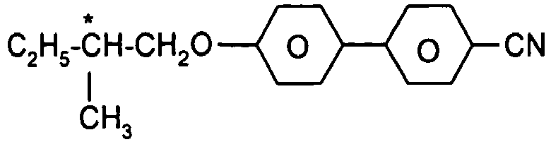
C 15 
CB 15 
CM 21 
R S-811 / S-811 
CM 44 
CM 45 
CM 47 
CN 
R-1011 / S-1011 
R-2011 / S-2011 
R-3011 / S-3011 
R-4011 / S-4011 
R-5011 / S-5011 - Die Schaltschicht enthält weiterhin bevorzugt einen oder mehrere Stabilisatoren. Die Gesamtkonzentration der Stabilisatoren liegt bevorzugt zwischen 0.00001 % und 10 %, besonders bevorzugt zwischen 0.0001 % und 1 % der Gesamtmischung. Die Konzentration dieser Verbindungen und anderer Mindermengenkomponenten wird bei der Angabe der Konzentrationen der flüssigkristallinen Verbindungen und des Polymers vernachlässigt.
- Bevorzugte Stabilisatorverbindungen sind in der folgenden Tabelle gezeigt:


- Gemäß einer bevorzugten Ausführungsform der Erfindung enthält die Schaltschicht weniger als 1 Gew.-% dichroitische Farbstoffmoleküle, besonders bevorzugt weniger als 0.1 Gew-% dichroitische Farbstoffmoleküle und ganz besonders bevorzugt weniger als 0.01 Gew-% dichroitische Farbstoffmoleküle.
- Insbesondere stellen sogenannte Guest-Host-Systeme, in denen dichroitische Farbstoffmoleküle in ein flüssigkristallines Material hineindotiert werden, keine bevorzugte Ausführungsform der Erfindung dar.
- Das Polymer wird bevorzugt durch Polyadditionsreaktion aus entsprechenden gleichen oder verschiedenen Monomeren gebildet. Bevorzugt erfolgt die Polymerisationsreaktion über eine photochemisch initiierte Reaktion, sie kann erfindungsgemäß aber auch thermisch gestartet werden. Besonders bevorzugt wird das Polymer durch UV-Licht-induzierte Polyadditionsreaktion gebildet.
- Eine solche Art der Polymerisation hat den Vorteil, dass verglichen mit anderen Polymerisationsarten eine höhere Reinheit des Polymers erreicht werden kann. Weiterhin ist die UV-Licht-induzierte Polymerisationsreaktion hervorragend steuerbar und läuft sehr schnell ab. Nochmals weiterhin werden unerwünschte Nebenreaktionen wie Zersetzung oder Oxidation der Mischungskomponenten vermieden.
- Bevorzugt wird das Polymer aus Monomerverbindungen enthaltend jeweils eine oder mehrere Gruppen gewählt aus Acrylatgruppen, Vinylethergruppen und Epoxidgruppen gebildet. Besonders bevorzugt sind Monomerverbindungen enthaltend eine, zwei, drei oder vier Acrylatgruppen, ganz besonders bevorzugt sind Monomerverbindungen enthaltend eine oder zwei Acrylatgruppen (sogenannte Monoacrylate bzw. Diacrylate).
- Erfindungsgemäß bevorzugt sind Monomere, welche reaktive Gruppen lediglich eines Typs aufweisen, beispielsweise ausschließlich Acrylatgruppen. Es können jedoch auch Monomere verwendet werden, welche gemischtfunktionell sind, d. h. jeweils eine oder mehrere reaktive Gruppen eines Typs und eine oder mehrere reaktive Gruppen eines anderen Typs aufweisen, beispielsweise eine Acrylatgruppe und eine Epoxidgruppe.
- Unter einer Acrylatgruppe wird im Rahmen der vorliegenden Erfindung bevorzugt eine Gruppe der folgenden Formel (A-1) verstanden:

- Weiterhin bevorzugt ist es, dass das Polymer aus zwei oder mehr verschiedenen Monomerverbindungen gebildet wird, wobei mindestens eine Monomerverbindung eine monofunktionelle Verbindung, bevorzugt ein Monoacrylat, darstellt und mindestens eine andere Monomerverbindung eine multifunktionelle Verbindung, bevorzugt ein Diacrylat, darstellt.
- Bevorzugt liegt dabei die multifunktionelle Verbindung in einem Anteil von maximal 80 % an allen Monomerverbindungen vor, besonders bevorzugt in einem Anteil von maximal 70 % und ganz besonders bevorzugt in einem Anteil von maximal 60 %. Bevorzugt gelten diese Bedingungen für das Diacrylat-Monomer.
- Das Verhältnis von Diacrylat zu Monoacrylat in der Mischung beträgt bevorzugt 1:20 bis 2:1, besonders bevorzugt 1:15 bis 3:2 und ganz besonders bevorzugt 1:10 bis 1:1.
- Es ist bevorzugt, dass mindestens ein Monomer in der Polymerisationsreaktion, in der das Polymer der Schaltschicht des erfindungsgemäßen Schaltelements gebildet wird, eine oder mehrere mesogene Gruppen enthält.
- Bevorzugt ist in der Polymerisationsreaktion, in der das Polymer gebildet wird, der Anteil der Monomere enthaltend eine oder mehrere mesogene Gruppen bezogen auf die Gesamtmenge der eingesetzten Monomere mindestens 10 %. Besonders bevorzugt ist er mindestens 30 %, ganz besonders bevorzugt mindestens 60 % und stärker bevorzugt mindestens 90%.
- Es ist besonders bevorzugt, dass im wesentlichen alle Monomere zur Herstellung des Polymers eine oder mehrere mesogene Gruppen aufweisen.
- Ein Vorteil der Verwendung von Monomeren enthaltend mesogene Gruppen liegt darin, dass die flüssigkristalline Phase über einen weiten Konzentrationsbereich an eingesetztem Monomer stabil ist. Weiterhin wurde gefunden, dass die Verwendung von Monomeren enthaltend mesogene Gruppen die Homogenität der erhaltenen Mischung verbessert und die Lichtstreuung verringert.
- Für den Fall, dass mindestens zwei verschiedene Monomere in der Polymerisationsreaktion verwendet werden, kann es bevorzugt sein, dass mindestens ein Monomer keine mesogene Gruppe aufweist und dass mindestens ein Monomer eine oder mehrere mesogene Gruppen aufweist.
- Bevorzugt weisen Monomerverbindungen gemäß der vorliegenden Erfindung eine Grundstruktur der Formel (M-1) oder (M-2) auf:


- Weiterhin stellt die Gruppe S eine beliebige Abstandsgruppe dar. Sie kann eine Einfachbindung, ein einzelnes Atom oder eine Kette mit einer Länge von 2 bis 20 Atomen darstellen. Bevorzugt stellt sie eine Kette mit einer Länge von 2 bis 10 Atomen dar, besonders bevorzugt eine Alkylen-, Alkylenoxy- oder Alkylendioxygruppe. In Abgrenzung zur mesogenen Gruppe stellt die Abstandsgruppe eine flexible Gruppe dar, die sich frei in allen Raumrichtungen ausrichten und bewegen kann, während die mesogene Gruppe typischerweise eingeschränkte Beweglichkeit aufweist.
- Die Gruppe R stellt eine beliebige reaktive Gruppe dar, welche in der Polyadditionsreaktion polymerisieren kann, bevorzugt eine Acrylat-, Vinylether- oder Epoxidgruppe. Der Index n weist einen Wert von 2 bis 5 auf, bevorzugt von 2 bis 4 und besonders bevorzugt von 2.
- Besonders bevorzugt sind Monomerverbindungen gemäß Formel (M-1) oder Formel (M-2), welche einer der beiden Formeln (M-1-1) oder (M-2-1) entsprechen


- Besonders bevorzugt sind weiterhin Monomerverbindungen gemäß Formel (M-1) oder Formel (M-2), welche einer der beiden Formeln (M-1-2) oder (M-2-2) entsprechen

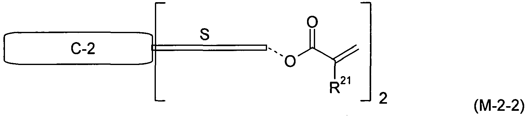
- Besonders bevorzugte Monomerverbindungen gemäß Formel (M-1-1) sind im Folgenden abgebildet:


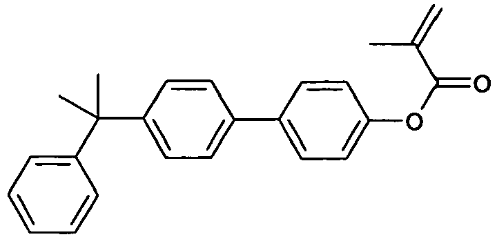


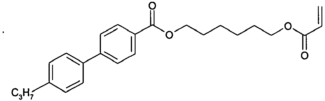











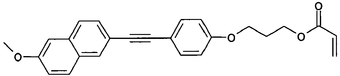








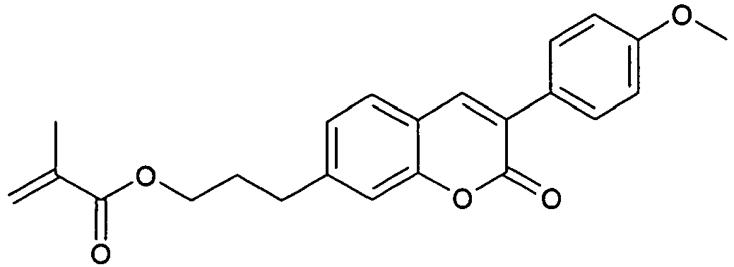


RM-M1 - Besonders bevorzugte Monomerverbindungen gemäß Formel (M-2-1) sind im Folgenden abgebildet:


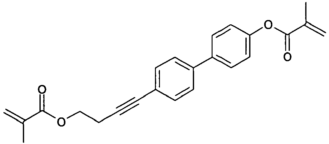













RM-D1 - Besonders bevorzugte Monomerverbindungen gemäß Formel (M-1-2) sind im Folgenden abgebildet:



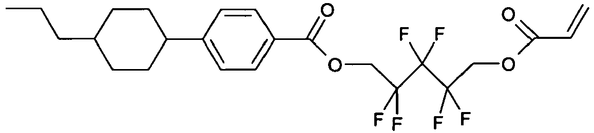
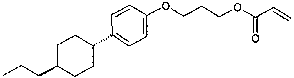


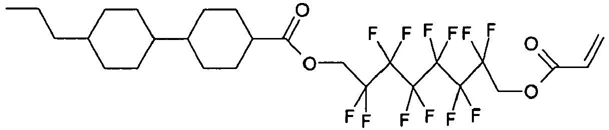


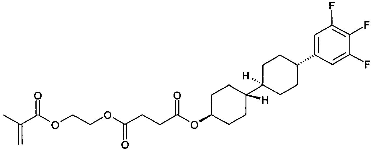


RM-M2 - Besonders bevorzugte Monomerverbindungen gemäß Formel (M-2-2) sind im Folgenden abgebildet:



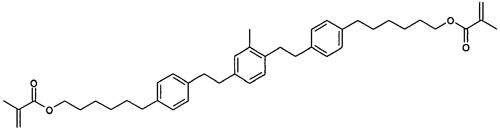


RM-D2 - Es kann auch bevorzugt sein, neben den oben genannten Monomeren der Formeln (M-1) oder (M-2) auch Monomere einzusetzen, welche keine mesogene Gruppe aufweisen. Solche Monomere können eine oder mehrere reaktive Gruppen, bevorzugt Acrylatgruppen, Vinylethergruppen oder Epoxidgruppen, aufweisen. Besonders bevorzugt weisen sie eine, zwei, drei oder vier Acrylatgruppen auf. Bevorzugte Monomerverbindungen dieses Typs sind in der folgenden Tabelle abgebildet:


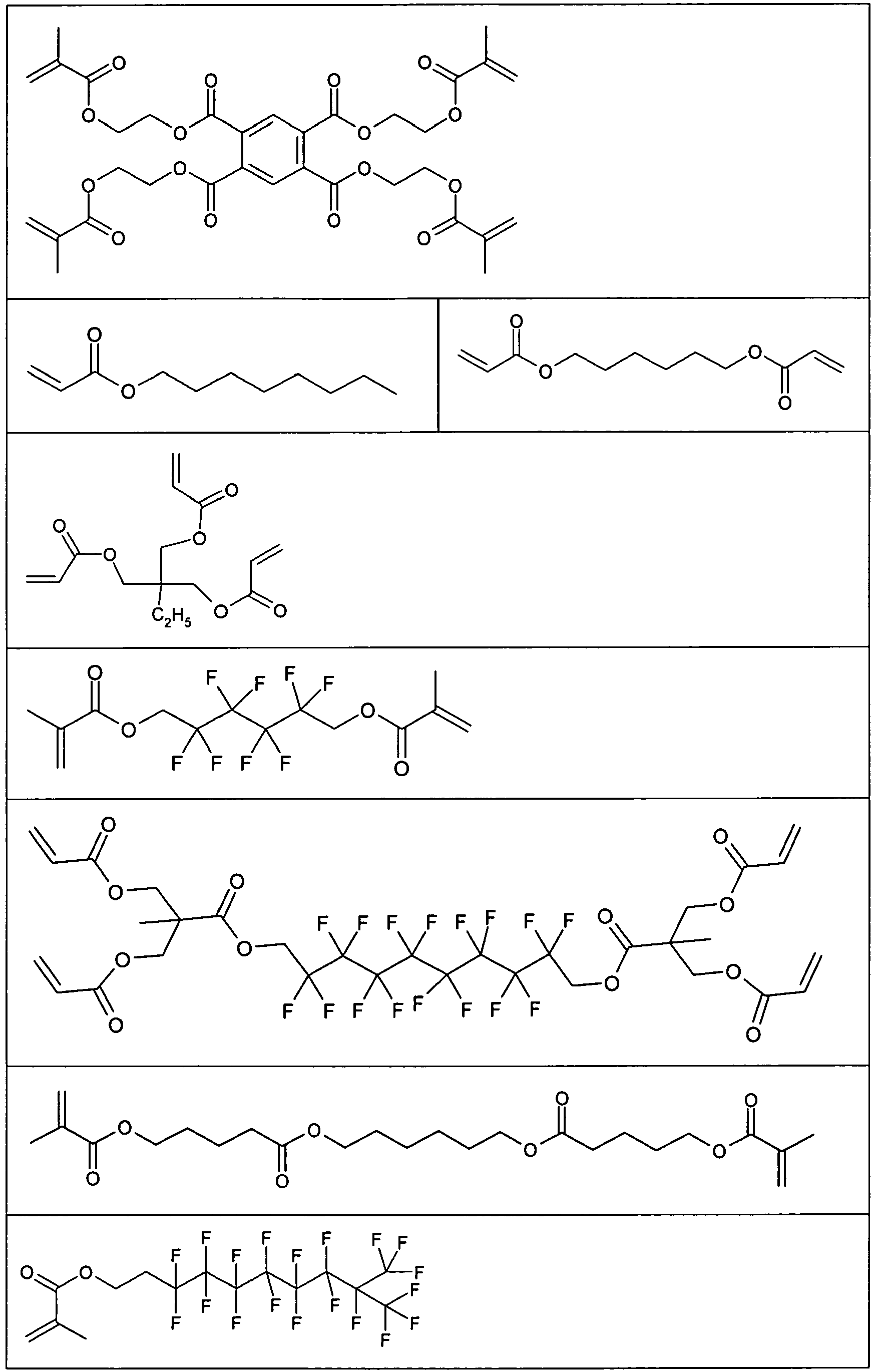

- Zur Herstellung von erfindungsgemäßen Schaltelementen des oben genannten Typs A werden bevorzugt zu einem überwiegendem Anteil monofunktionelle Monomere, besonders bevorzugt Monomere mit genau einer Acrylatgruppe, eingesetzt. Bevorzugt beträgt der Anteil der genannten bevorzugten Monomere mehr als 60 % der Gesamtmenge der eingesetzten Monomere, besonders bevorzugt mehr als 80 % der Gesamtmenge der Monomere und ganz besonders bevorzugt mehr als 95 % der Gesamtmenge der Monomere.
- Ganz besonders bevorzugt werden zu einem überwiegenden Anteil Monomere der oben aufgeführten Formel (M-1-2) eingesetzt, noch stärker bevorzugt werden zu einem überwiegenden Anteil Monomere der Formel (M-1-2) gemäß der obenstehenden Tabelle eingesetzt.
- Zur Herstellung von erfindungsgemäßen Schaltelementen des oben genannten Typs B werden bevorzugt zu einem überwiegendem Anteil multifunktionelle Monomere, besonders bevorzugt Monomere mit genau zwei Acrylatgruppen, eingesetzt. Bevorzugt beträgt der Anteil der genannten bevorzugten Monomere mehr als 40 % der Gesamtmenge der eingesetzten Monomere, besonders bevorzugt mehr als 60 % der Gesamtmenge der Monomere und ganz besonders bevorzugt mehr als 80 % der Gesamtmenge der eingesetzten Monomeren.
- Ganz besonders bevorzugt werden zu einem überwiegenden Anteil Monomere der oben aufgeführten Formel (M-2-1) oder (M-2-2) eingesetzt, noch stärker bevorzugt werden zu einem überwiegenden Anteil Monomere der Formel (M-2-1) gemäß der obenstehenden Tabelle eingesetzt.
- Die Herstellung der Mischung der Schaltschicht, enthaltend mindestens eine flüssigkristalline Verbindung sowie mindestens ein Polymer, kann auf unterschiedliche Art und Weise erfolgen.
- Bevorzugt ist eine Ausführungsform, bei der das Polymer durch Polymerisationsreaktion mindestens einer Monomerverbindung in Anwesenheit der flüssigkristallinen Verbindung hergestellt wird (in situ-Verfahren).
- Unter Polymerisation in Anwesenheit der flüssigkristallinen Verbindung wird dabei insbesondere verstanden, dass eine Mischung enthaltend mindestens eine flüssigkristalline Verbindung sowie mindestens eine Monomerverbindung hergestellt wird, und dass anschließend die Polymerisationsreaktion durchgeführt wird, in der die mindestens eine Monomerverbindung zu einem Polymer reagiert. Das genannte Polymer liegt in diesem Fall nach Abschluss der Polymerisationsreaktion zusammen mit der mindestens einen flüssigkristallinen Verbindung in der Mischung vor. Die erhaltene Mischung kann direkt zur Herstellung der Schaltschicht verwendet werden oder weiteren Verarbeitungsschritten unterworfen werden.
- Weiterer Gegenstand der Erfindung ist daher die Verwendung einer Mischung enthaltend mindestens eine flüssigkristalline Verbindung sowie mindestens eine Monomerverbindung zur Herstellung des erfindungsgemäßen Schaltelements.
- Bevorzugt ist die Verwendung der Mischung enthaltend mindestens eine flüssigkristalline Verbindung sowie mindestens eine Monomerverbindung zur Herstellung der erfindungsgemäßen Schaltelements, wobei die Mischung dadurch gekennzeichnet ist, dass sie mindestens eine Monomerverbindung aufweist, welche ein Monoacrylat darstellt, und mindestens eine Monomerverbindung aufweist, welche ein Diacrylat darstellt.
- Die Monomerverbindung, welche ein Monoacrylat darstellt, ist dabei bevorzugt ausgewählt aus Verbindungen der oben gezeigten Formel (M-1), besonders bevorzugt aus Verbindungen der oben gezeigten Formeln (M-1-1) und (M-1-2). Ganz besonders bevorzugt sind die oben gezeigten expliziten Verbindungen gemäß den Formeln (M-1-1) und (M-1-2).
- Die Monomerverbindung, welche ein Diacrylat darstellt, ist dabei bevorzugt ausgewählt aus Verbindungen der oben gezeigten Formel (M-2), besonders bevorzugt aus Verbindungen der oben gezeigten Formeln (M-2-1) und (M-2-2). Ganz besonders bevorzugt sind die oben gezeigten expliziten Verbindungen gemäß den Formeln (M-2-1) und (M-2-2).
- Die Polymerisationsreaktion der mindestens einen Monomerverbindung, in der das mindestens eine Polymer in Mischung mit der mindestens einen flüssigkristallinen Verbindung erhalten wird, stellt bevorzugt eine UV-Licht-induzierte Polyaddition dar.
- Bevorzugt ist in der oben genannten Mischung enthaltend mindestens eine flüssigkristalline Verbindung sowie mindestens eine Monomerverbindung zusätzlich mindestens eine Photoinitiator-Verbindung enthalten. Die mindestens eine Photoinitiator-Verbindung ist bevorzugt in einer Konzentration von 0.01 % bis 2 % und besonders bevorzugt in einer Konzentration von 0.1 % bis 1 % in der Mischung vorhanden.
- Bevorzugte Photoinitiator-Verbindungen gemäß der vorliegenden Erfindung sind in der folgenden Tabelle abgebildet:


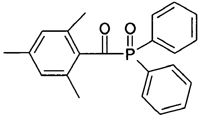


Irgacure 651 

Irgacure 907 


- Bevorzugte Beleuchtungssysteme zur Einleitung der Polymerisationsreaktion der Monomeren sind quecksilberbasierte Beleuchtungssysteme, beispielsweise H-, F- und G-Strahler. Besonders bevorzugt sind F-Strahler oder andere Beleuchtungssysteme mit niedrigem UV-B-Anteil und hohem UV-A-Anteil. Bevorzugterweise wird ein Filter verwendet, welcher Licht einer Wellenlänge von weniger als 320 nm, bevorzugt weniger als 340 nm und besonders bevorzugt weniger als 360 nm blockiert.
- Weiterhin ist in der oben genannten Mischung enthaltend mindestens eine flüssigkristalline Verbindung und mindestens eine Monomerverbindung zusätzlich mindestens eine Verbindung enthalten, welche als Kettenübertragungsmittel (chain-transfer agent) wirkt. Chain-transfer agents reagieren in der Polymerisationsreaktion mit dem Polymer-Radikal zu einem Radikal und einem abgesättigten Polymer, welches nicht weiter reagiert. Das entstandene Radikal des Chain-transfer agents ist in der Lage, eine neue Polymerisationsreaktion zu initiieren. Durch die Verwendung von Chain-transfer agents kann unter anderem das Molekulargewicht der in der Polymerisationsreaktion erhaltenen Polymere kontrolliert werden.
- Die chain-transfer agents sind bevorzugt in einer Konzentration von 0.1 % bis 10 %, besonders bevorzugt 1 % bis 8 % in der Mischung vorhanden. Die Konzentration dieser Verbindungen und anderer Mindermengenkomponenten wird bei der Angabe der Konzentrationen der flüssigkristallinen Verbindungen und des Polymers vernachlässigt.
- Gemäß der vorliegenden Erfindung bevorzugt verwendete Chain-transfer agents enthalten mindestens eine C-Halogen, S-H, Si-H oder S-S-Bindung. Besonders bevorzugte Chain-transfer agents sind ausgewählt aus der Gruppe enthaltend die folgende Verbindung

- Alternativ und ebenfalls bevorzugt ist eine Ausführungsform, gemäß der das Polymer durch Polymerisationsreaktion mindestens einer Monomerverbindung hergestellt wird, wobei die Schaltschicht enthaltend die flüssigkristalline Verbindung sowie das Polymer anschließend durch Mischen des Polymers und der flüssigkristallinen Verbindung hergestellt wird (zweischrittiges Verfahren).
- Gegenstand der Erfindung ist somit auch die Verwendung einer Mischung enthaltend mindestens eine flüssigkristalline Verbindung sowie mindestens ein durch Polyadditionsreaktion erhaltenes Polymer zur Herstellung des erfindungsgemäßen Schaltelements.
- Gemäß dieser Ausführungsform (zweischrittiges Verfahren) erfolgt, wie oben ausgeführt, eine Polymerisationsreaktion der mindestens einen Monomerverbindung, ohne dass gleichzeitig die mindestens eine flüssigkristalline Verbindung in der Mischung vorhanden ist. Die Polymerisation erfolgt bevorzugt in einem für Polymerisationsreaktionen typischerweise verwendeten Lösungsmittel, besonders bevorzugt in THF, Toluol, Butyrolacton oder NMP. Im Anschluss an die Polymerisation wird das Lösungsmittel entfernt und das Polymer mit der mindestens einen flüssigkristallinen Verbindung gemischt. Die erhaltene Mischung kann direkt zur Herstellung der Schaltschicht verwendet werden oder weiteren Verarbeitungsschritten unterworfen werden.
- Zur Herstellung des Polymers können im zweischrittigen Verfahren analoge Verfahren wie beim in-situ-Verfahren angewendet werden, beispielsweise eine UV-Licht-induzierte Polyadditionsreaktion. Es können jedoch, aufgrund der abweichenden Rahmenbedingungen bei diesem Verfahren, auch andere Herstellverfahren für das Polymer eingesetzt werden.
- Speziell geeignet und angepasst zur Verwendung zur Herstellung des erfindungsgemäßen Schaltelements ist eine Mischung enthaltend mindestens eine flüssigkristalline Verbindung, mindestens eine Monomerverbindung, welche eine monofunktionelle Verbindung, bevorzugt eine Monoacrylatverbindung darstellt, sowie mindestens eine Monomer verbindung, welche eine multifunktionelle Verbindung, bevorzugt eine Diacrylatverbindung darstellt, wobei mindestens eine Monomerverbindung eine oder mehrere mesogene Gruppen enthält. Eine solche Mischung ist daher ebenfalls Gegenstand der vorliegenden Erfindung.
- Die Monomerverbindungen können dabei hohe Werte für die Doppelbrechung Δn aufweisen, oder sie können niedrige Werte für die Doppelbrechung Δn aufweisen.
- Die Mischung wird erfindungsgemäß in einem folgenden Verfahrensschritt einer Polymerisationsreaktion unterzogen.
- Weiterer Gegenstand der Erfindung ist daher die Mischung, welche aus der Polymerisationsreaktion der oben genannten Mischung resultiert.
- Bevorzugte Ausführungsformen der flüssigkristallinen Verbindung, der monofunktionellen Monomer-Verbindung, der multifunktionellen Monomer-Verbindung, der Monoacrylatverbindung und der Diacrylatverbindung in den oben genannten Mischungen sind dieselben wie oben aufgeführt.
- Im Rahmen der vorliegenden Erfindung wurde gefunden, dass die Verwendung von hohen Konzentrationen von Monomerverbindungen mit hohen Werten für die Doppelbrechung zu einer Erhöhung der Resttransmission und einer Verringerung der Empfindlichkeit des Schaltvorgangs führt (Typ B des Schaltelements, vgl. oben).
- Umgekehrt kann durch die Verwendung von Monomerverbindungen mit niedrigen Werten für die Doppelbrechung und/oder durch die Verwendung von niedrigen Konzentrationen von Monomerverbindungen eine geringe Resttransmission und eine hohe Empfindlichkeit des Schaltvorgangs erreicht werden (Typ A des Schaltelements, vgl. oben).
- Die vorliegende Erfindung ermöglicht es daher, die Eigenschaften des Schaltelements zwischen den Typen A und B variabel einzustellen.
- Insbesondere wurde im Rahmen der vorliegenden Erfindung gefunden, dass das Verhältnis der Anteile von multifunktionellem zu monofunktionellem Monomer hohen Einfluss auf die Eigenschaften des Schaltelements hat. Durch eine Variation der Anteile können die Eigenschaften des Schaltelements zwischen den Typen A und B variabel eingestellt werden.
- Nochmals insbesondere wurde gefunden, dass Monomerverbindungen mit zwei oder mehr Acrylatgruppen eine größere Wirkung auf die Resttransmission und die Empfindlichkeit des Schaltvorgangs haben als Monomerverbindungen mit einer Acrylatgruppe.
- Die Verwendung von Monomerverbindungen mit zwei oder mehr Acrylatgruppen und mit hoher Doppelbrechung Δn führt zu Schaltelementen des Typs B, insbesondere wenn hohe Konzentrationen dieser Monomerverbindungen eingesetzt werden.
- Hingegen wurde gefunden, dass die Verwendung von Monomerverbindungen mit einer Acrylatgruppe und mit hoher Doppelbrechung Δn alleine, auch in hoher Konzentration, nicht zu Schaltelementen des Typs B führt, d. h. keine relevante Erhöhung der Resttransmission und keine relevante Verringerung der Empfindlichkeit des Schaltvorgangs bewirkt. Besonders bevorzugt ist daher die Verwendung einer Mischung enthaltend mindestens eine flüssigkristalline Verbindung, mindestens eine Monoacrylatverbindung und mindestens eine Diacrylatverbindung in dem oben genannten Schaltelement des Typs B, wobei die Diacrylatverbindung eine Doppelbrechung Δn von mehr als 0.1, bevorzugt von mehr als 0.12 und besonders bevorzugt von mehr als 0.15 aufweist und in einer Konzentration von mehr als 4 %, bevorzugt von mehr als 6 % und ganz besonders bevorzugt von mehr als 8 % eingesetzt wird.
- Weiterhin besonders bevorzugt ist daher die Verwendung einer Mischung enthaltend mindestens eine flüssigkristalline Verbindung, mindestens eine Monoacrylatverbindung und mindestens eine Diacrylatverbindung in dem oben genannten Schaltelement des Typs A, wobei die Diacrylatverbindung eine Doppelbrechung Δn von weniger als 0.15, bevorzugt von weniger als 0.12 und besonders bevorzugt von weniger als 0.1 aufweist und/oder in einer Konzentration von weniger als 4 %, besonders bevorzugt von weniger als 3 % und ganz besonders bevorzugt von weniger als 2 % eingesetzt wird.
- Die folgenden Ausführungsbeispiele sollen die vorliegende Erfindung näher darstellen und verdeutlichen. Sie sollen nicht einschränkend bezüglich des Umfangs der Erfindung ausgelegt werden.
- Es werden die Mischungen 1, 2, 3 und 4 zubereitet. Sie enthalten jeweils die LC-Mischung A, welche die folgende Zusammensetzung aufweist:
LC-Mischun A LC-Verbindung % 
2 PZG-3-N 
9 PZG-4-N 
9 PZG-5-N 
10 PZP-1-5 
17 PZP-10-1 
16 PZP-1O-5 
12 CP-3-N 
10 PP-2-N 
9 PGU-3-F 
3 CPZG-3-N 
3 CPZG-4-N - S-811 ist ein chiraler Dotand (Struktur s. Beschreibung). Die mit dem Kürzel RM bezeichneten Verbindungen sind Monomere. Ihre Strukturen sind in einer obenstehenden Tabelle abgebildet. Die Mischungen 2 und 4 entsprechen jeweils den Mischungen 1 und 3 mit dem Unterschied, dass die Starterverbindung Irgacure (Struktur s. Beschreibung) zugefügt wurde und die Polymerisation durchgeführt wurde.
- Mischung 1: LC-Mischung A + 0,1% S-811 + 1,8% RM-D1 (Diacrylat) + 18,2% RM-M1 (Monoacrylat).
- Mischung 2: LC-Mischung A + 0,1% S-811 + 1,8% RM-D1 (Diacrylat) + 18,2% RM-M1 (Monoacrylat). + 0,2% Irgacure 907. Polymerisierter Zustand
- Mischung 3: LC-Mischung A + 0,1% S-811 + 10% RM-D1 (Diacrylat) + 10% RM-M1 (Monoacrylat).
- Mischung 4: LC-Mischung A + 0,1% S-811 + 10% RM-D1 (Diacrylat) + 10% RM-M1 (Monoacrylat). + 0,2% Irgacure 907. Polymerisierter Zustand.
- Die Mischungen werden in ein erfindungsgemäßes Schaltelement eingebracht und stellen darin die Schaltschicht dar. Die Schaltschicht liegt in der Ausführungsform einer TN-Zelle von 4 Mikrometern Schichtdicke vor. Die Polarisatoren des Schaltelements befinden sich in gekreuzter Stellung (90°).
- In
Fig. 1 wird die Transmissionsänderung für die vier Mischungen jeweils in Abhängigkeit von der Temperatur gezeigt. - Es ist deutlich erkennbar, dass auch nach Polymerisation eine S-förmige Kurve für die Transmission in Abhängigkeit von der Temperatur erhalten wird, d. h. eine weitgehend konstante Transmission in den beiden Bereichen mit deutlich höherer Temperatur bzw. deutlich niedrigerer Temperatur als der Temperatur des Klärpunkt und eine sich rasch mit der Temperatur ändernde Transmission in der Nähe der Temperatur des Klärpunkts. Der Klärpunkt ist für die Kurve 2 verglichen mit der Kurve 1 deutlich hin zu höheren Temperaturen verschoben, für die Kurve 4 verglichen mit der Kurve 3 deutlich hin zu niedrigeren Temperaturen. Die Kurven 2 und 4 weisen eine Resttransmission im "geschlossenen Zustand" auf sowie eine verringerte Empfindlichkeit des Schaltvorgangs in Abhängigkeit von der Temperatur (weniger steile Kurve im Bereich des Klärpunkts). Kurven 2 und 4 und 4 unterscheiden sich untereinander insbesondere in Bezug auf die Resttransmission bei höheren Temperaturen. Diese ist bei Kurve 4 deutlich höher als bei Kurve 2.
- Weiterhin ist hervorzuheben, dass die Mischungen 2 und 4 ein homogenes Aussehen und keine sichtbare Lichtstreuung aufweisen.
- Es werden die Mischungen 1, 2, 3 und 4 zubereitet und polymerisiert (curing 3 Min,, 360 nm Kantenfilter, 37 mW/cm2).
- Sie enthalten alle die folgende Grundmischung:
- 59,7% LC-Mischung A + 5% CGPC-3-3 + 5% CPZG-3-N + 0,1% S-811 + 0,2% Irgacure 651
- Zusätzlich enthält die Mischung 1:
- 15% RM-M2 (Monoacrylat, niedriges Delta-n) + 15% RM-D2 (Diacrylat, niedriges Delta-n)
- Zusätzlich enthält die Mischung 2:
- 15% RM-M1 (Monoacrylat, hohes Delta-n) + 15% RM-D2 (Diacrylat, niedriges Delta-n)
- Zusätzlich enthält die Mischung 3:
- 15% RM-M2 (Monoacrylat, niedriges Delta-n) + 15% RM-D1 (Diacrylat, hohes Delta-n)
- Zusätzlich enthält die Mischung 4:
- 15% RM-M1 (Monoacrylat, hohes Delta-n) + 15% RM-D1 (Diacrylat, hohes Delta-n)
- Die Substanzeigenschaften der Monomere RM-M2, RM-M1, RM-D2 und RM-D1 sind in der folgenden Tabelle aufgeführt (Strukturen vgl. obenstehende Tabelle).
Substanz Acrylattyp Extrapolierter Klärpunkt Extrapoliertes Delta-n RM-M2 Monoacrylat -27,7 °C 0,0196 RM-M1 Monoacrylat 57,4°C 0,1329 RM-D2 Diacrylat -22,0°C 0,0874 RM-D1 Diacrylat 138,5°C 0,1490 - Die Mischungen werden in ein erfindungsgemäßes Schaltelement eingebracht und stellen darin die Schaltschicht dar. Die Schaltschicht liegt in der Ausführungsform einer TN-Zelle von 4 Mikrometern Schichtdicke vor. Die Polarisatoren des Schaltelements befinden sich in gekreuzter Stellung (90°).
- In
Fig. 2 wird die Transmissionsänderung für die vier Mischungen jeweils in Abhängigkeit von der Temperatur gezeigt. - Erneut weisen die Mischungen ein homogenes Aussehen und keine sichtbare Lichtstreuung auf.
- Man erkennt deutlich, dass sich die Resttransmission mit Übergang von Mischung 1 über Mischung 2 über Mischung 3 hin zu Mischung 4 erhöht. Weiterhin verringert sich die Empfindlichkeit des Schaltvorgangs von Mischung 1 über Mischung 2 über Mischung 3 hin zu Mischung 4.
- Das Schaltelement enthaltend Mischung 1 stellt ein Schaltelement des Typs A dar (geringe Resttransmission und hohe Empfindlichkeit des Schaltvorgangs), während das Schaltelement enthaltend Mischung 4 ein Schaltelement des Typs B darstellt (hohe Resttransmission und geringe Empfindlichkeit des Schaltvorgangs). Die Schaltelemente enthaltend Mischung 2 bzw. Mischung 3 stellen Übergangsformen dar.
- Das vorliegende Beispiel zeigt also, wie durch geeignete Wahl von Mono- und Diacrylaten mit unterschiedlichen Werten für die Doppelbrechung unterschiedliche Transmissionskurven der Schaltelemente erhalten werden können, entsprechend den oben und in der Beschreibung dargestellten Typen A und B des erfindungsgemäßen Schaltelements.
- Es werden 10 Mischungen hergestellt, welche alle die Komponenten LC-Mischung A, CPZG-3-N, CGPC-3-3, Irgacure 651 und S-811 enthalten. Zusätzlich sind in steigendem Anteil (4% bis 40%) die Monomerverbindungen RM-M2 und RM-D1 (vgl. oben) im Verhältnis 1:1 enthalten.
- Die genauen Konzentrationen der Mischungen sind wie folgt:
- LC-Mischung A (89.7-x%) + CPZG-3-N (5%) + CGPC-3-3 (5%) + Irgacure 651 (0,2%) + S-811 (0,1%) + x/2 % RM-M2 + x/2 % RM-D1, wobei
- x = 4% für Mischung 1
- x = 6% für Mischung 2
- x = 8% für Mischung 3
- x = 10% für Mischung 4
- x = 12% für Mischung 5
- x = 15% für Mischung 6
- x = 17% für Mischung 7
- x = 20% für Mischung 8
- x = 30% für Mischung 9
- x = 40% für Mischung 10.
- Die Monomere stellen jeweils ein Monoacrylat mit niedriger Doppelbrechung (RM-M2) und ein Diacrylat mit hoher Doppelbrechung (RM-D1) dar.
- Die Mischungen werden in ein erfindungsgemäßes Schaltelement eingebracht und stellen darin die Schaltschicht dar. Die Schaltschicht liegt in der Ausführungsform einer TN-Zelle von 4 Mikrometern Schichtdicke vor. Die Polarisatoren des Schaltelements befinden sich in gekreuzter Stellung (90°).
- In
Fig. 3 wird die Transmissionsänderung für die Mischungen jeweils in Abhängigkeit von der Temperatur gezeigt. - Das Beispiel zeigt, dass wie in Beispiel 2 ein Übergang zwischen Schaltelementen des Typs A zu Schaltelementen des Typs B erreicht werden kann, diesmal durch Erhöhung der Konzentration der Monomere in der Mischung.
- Im Unterschied zu Beispiel 2 sind hier auch Mischungen mit sehr niedrigen Konzentrationen an eingesetztem Monomer gezeigt. In diesen Fällen kann eine sehr niedrige Resttransmission und eine hohe Empfindlichkeit des Schaltvorgangs erreicht werden.
- Es werden die Mischungen 1 bis 4 hergestellt und polymerisiert.
- Sie enthalten alle dieselbe Grundmischung:
- LC-Mischung A (99.7-x %), 0,1% S-811 und 0,2% Irgacure 907.
- Zusätzlich enthält Mischung 1:
- x=10% Monomere enthaltend RM-M1 (Monoacrylat) : RM-D1 (Diacrylat) = 10:1
- Zusätzlich enthält Mischung 2:
- x=20% Monomere enthaltend RM-M1 (Monoacrylat) : RM-D1 (Diacrylat) = 10:1
- Zusätzlich enthält Mischung 3:
- x=10% Monomere enthaltend RM-M1 (Monoacrylat) : RM-D1 (Diacrylat) = 1:1
- Zusätzlich enthält Mischung 4:
- x=20% Monomere enthaltend RM-M1 (Monoacrylat): RM-D1 (Diacrylat) = 1:1
- Die Mischungen werden in ein erfindungsgemäßes Schaltelement eingebracht und stellen darin die Schaltschicht dar. Die Schaltschicht liegt in der Ausführungsform einer TN-Zelle von 4 Mikrometern Schichtdicke vor. Die Polarisatoren des Schaltelements befinden sich in gekreuzter Stellung (90°).
- Erneut weisen die Mischungen ein homogenes Aussehen und keine sichtbare Lichtstreuung auf.
- In
Fig. 4 wird die Transmissionsänderung für die vier Mischungen jeweils in Abhängigkeit von der Temperatur gezeigt. - Es wird deutlich, dass mit Anstieg der Menge an eingesetztem Monomer in beiden Fällen (Mischung 2 gegenüber 1 und 4 gegenüber 3) eine erhöhte Resttransmission und eine geringere Empfindlichkeit des Schaltvorgangs auftritt.
- Es besteht jedoch ein deutlicher Unterschied zwischen den Mischungen 4 und 2 in Hinblick auf die Resttransmission: in der Mischung 4, welche einen hohen Anteil an Diacrylat (Verhältnis 1:1) enthält, ist die Resttransmission bei gleicher Gesamtkonzentration an Monomer deutlich höher als in der Mischung 2 mit niedrigem Anteil an Diacrylat (Verhältnis Diacrylat zu Monoacrylat 1:10).
- Die Empfindlichkeit des Schaltvorgangs ist jedoch bei beiden Mischungen ähnlich.
- Durch Variation den Anteils an Diacrylat bei gleicher Gesamtkonzentration an Monomer lässt sich daher die Höhe der Resttransmission weitgehend unabhängig von der Empfindlichkeit des Schaltvorgangs beeinflussen.


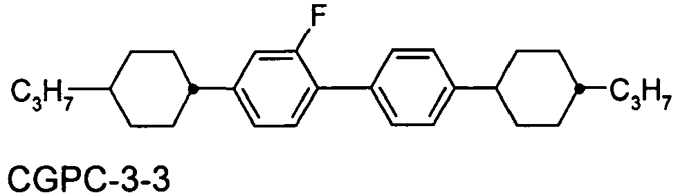
Claims (14)
- Temperaturgesteuertes Schaltelement zur Regulation des Lichtdurchtritts, enthaltend- einen ersten Polarisator- eine polarisationsbeeinflussende Schaltschicht, welche mindestens eine flüssigkristalline Verbindung sowie mindestens ein Polymer enthält, wobei das Polymer mindestens eine Wiederholeinheit enthaltend eine oder mehrere mesogene Gruppen umfasst, sowie- einen zweiten Polarisator,wobei die Schaltschicht zwischen den beiden Polarisatoren
angeordnet ist, dadurch gekennzeichnet dass das Polymer gebildet ist in einer Polymerisationsreaktion unter Einsatz von Monomeren enthaltend eine oder mehrere mesogene Gruppen, wobei der Anteil der Monomere enthaltend eine oder mehrere mesogene Gruppen bezogen auf die Gesamtmenge aller eingesetzten Monomere mindestens 90% beträgt. - Schaltelement nach Anspruch 1, dadurch gekennzeichnet, dass es als Schaltzustände einen Schaltzustand mit höherer Lichttransmission durch das Schaltelement und einen Schaltzustand mit geringerer Lichttransmission durch das Schaltelement aufweist.
- Schaltelement nach Anspruch 2, dadurch gekennzeichnet, dass der Schaltzustand mit höherer Lichttransmission durch das Schaltelement bei niedrigeren Temperaturen des Schaltelements vorliegt, und der Schaltzustand mit geringerer Lichttransmission bei höheren Temperaturen des Schaltelements vorliegt.
- Schaltelement nach Anspruch 2 oder 3, dadurch gekennzeichnet, dass der Zustand der Schaltschicht im Schaltzustand mit höherer Lichtdurchlässigkeit ein verdrillt nematischer Zustand ist, und dass der Zustand der Schaltschicht im Schaltzustand mit geringerer Lichtdurchlässigkeit ein isotroper Zustand ist.
- Schaltelement nach einem oder mehreren der Ansprüche 1 bis 4, dadurch gekennzeichnet, dass es in einer baulichen Öffnung eines Gebäudes oder eines sonstigen nach außen abgeschlossenen Kompartiments angebracht ist.
- Schaltelement nach einem oder mehreren der Ansprüche 1 bis 5, dadurch gekennzeichnet, dass es eine Flächenausdehnung von mindestens 0.05 m2 aufweist.
- Schaltelement nach einem oder mehreren der Ansprüche 1 bis 6, dadurch gekennzeichnet, dass es formflexibel und biegsam ist.
- Schaltelement nach einem oder mehreren der Ansprüche 1 bis 7, dadurch gekennzeichnet, dass das Polymer in der Schaltschicht in einem Anteil von höchstens 30 % vorliegt.
- Schaltelement nach einem oder mehreren der Ansprüche 1 bis 8, dadurch gekennzeichnet, dass das Polymer durch UV-Licht-induzierte Polyaddition gebildet wird.
- Schaltelement nach einem oder mehreren der Ansprüche 1 bis 9, dadurch gekennzeichnet, dass das Polymer aus zwei oder mehr verschiedenen Monomerverbindungen gebildet wird, wobei mindestens eine Monomerverbindung eine monofunktionelle Verbindung darstellt und mindestens eine andere Monomerverbindung eine multifunktionelle Verbindung darstellt.
- Schaltelement nach einem oder mehreren der Ansprüche 1 bis 10, dadurch gekennzeichnet, dass das Polymer aus Monomerverbindungen enthaltend jeweils eine oder mehrere Gruppen gewählt aus Acrylatgruppen, Vinylethergruppen und Epoxidgruppen gebildet wird.
- Verwendung des Schaltelements nach einem oder mehreren der Ansprüche 1 bis 11 zur temperaturabhängigen Beeinflussung der Lichttransmission und/oder des Wärmeeintrags in einen Innenraum.
- Verwendung nach Anspruch 12, wobei die Lichttransmission durch das Schaltelement im Bereich von 1000 bis 1500 nm Wellenlänge beeinflusst wird.
- Verwendung einer Mischung enthaltend mindestens eine flüssigkristalline Verbindung sowie mindestens eine Monomerverbindung enthaltend eine oder mehrere mesogene Gruppen, wobei der Anteil der Monomerverbindung enthaltend eine oder mehrere mesogene Gruppen bezogen auf die Gesamtmenge aller Monomerverbindungen in der Mischung mindestens 90% beträgt, zur Herstellung eines Schaltelements nach einem oder mehreren der Ansprüche 1 bis 11.
Priority Applications (1)
| Application Number | Priority Date | Filing Date | Title |
|---|---|---|---|
| EP12762537.4A EP2771735B1 (de) | 2011-10-24 | 2012-09-25 | Schaltelement enthaltend ein flüssigkristallines medium |
Applications Claiming Priority (4)
| Application Number | Priority Date | Filing Date | Title |
|---|---|---|---|
| EP11008518 | 2011-10-24 | ||
| US201261611193P | 2012-03-15 | 2012-03-15 | |
| EP12762537.4A EP2771735B1 (de) | 2011-10-24 | 2012-09-25 | Schaltelement enthaltend ein flüssigkristallines medium |
| PCT/EP2012/004003 WO2013060406A1 (de) | 2011-10-24 | 2012-09-25 | Schaltelement enthaltend ein flüssigkristallines medium |
Publications (2)
| Publication Number | Publication Date |
|---|---|
| EP2771735A1 EP2771735A1 (de) | 2014-09-03 |
| EP2771735B1 true EP2771735B1 (de) | 2018-01-24 |
Family
ID=48167148
Family Applications (1)
| Application Number | Title | Priority Date | Filing Date |
|---|---|---|---|
| EP12762537.4A Active EP2771735B1 (de) | 2011-10-24 | 2012-09-25 | Schaltelement enthaltend ein flüssigkristallines medium |
Country Status (7)
| Country | Link |
|---|---|
| US (1) | US9507185B2 (de) |
| EP (1) | EP2771735B1 (de) |
| JP (1) | JP6165750B2 (de) |
| KR (1) | KR101933248B1 (de) |
| CN (1) | CN103890643B (de) |
| TW (1) | TWI579370B (de) |
| WO (1) | WO2013060406A1 (de) |
Families Citing this family (9)
| Publication number | Priority date | Publication date | Assignee | Title |
|---|---|---|---|---|
| JP2016536634A (ja) | 2013-10-17 | 2016-11-24 | メルク パテント ゲゼルシャフト ミット ベシュレンクテル ハフツングMerck Patent Gesellschaft mit beschraenkter Haftung | 光の進入を制御するためのデバイス |
| CN107548471B (zh) * | 2015-04-27 | 2021-07-02 | 默克专利股份有限公司 | 用于光学切换元件的光学切换层 |
| EP3319964B1 (de) * | 2015-07-10 | 2020-07-22 | Merck Patent GmbH | Dithioalkylpyrrolopyrrole und ihre verwendung als farbstoffe |
| US12031078B2 (en) | 2016-07-20 | 2024-07-09 | Merck Patent Gmbh | Switching layer for use in an optical switching element |
| CN109752893B (zh) * | 2017-11-03 | 2021-02-02 | 北京大学 | 一种对可见光和近红外光透过率分段调控的温控调光膜及其制备方法 |
| CN109116650B (zh) * | 2018-08-31 | 2022-02-18 | 华南师范大学 | 一种电响应调光器件及其制备方法 |
| CN113195683B (zh) * | 2018-12-19 | 2025-01-10 | 默克专利股份有限公司 | 用于切换元件的切换层 |
| CN111505878A (zh) * | 2020-05-25 | 2020-08-07 | 珠海兴业新材料科技有限公司 | 热转变液晶基薄膜、其制备方法及智能窗户 |
| KR102831881B1 (ko) * | 2022-12-02 | 2025-07-09 | (주)세경하이테크 | 원편광된 그라디언트 콜레스테릭 액정을 적층한 전반사 필름 제조방법 |
Family Cites Families (17)
| Publication number | Priority date | Publication date | Assignee | Title |
|---|---|---|---|---|
| US6025897A (en) | 1993-12-21 | 2000-02-15 | 3M Innovative Properties Co. | Display with reflective polarizer and randomizing cavity |
| US6099758A (en) | 1997-09-17 | 2000-08-08 | Merck Patent Gesellschaft Mit Beschrankter Haftung | Broadband reflective polarizer |
| US7023602B2 (en) | 1999-05-17 | 2006-04-04 | 3M Innovative Properties Company | Reflective LCD projection system using wide-angle Cartesian polarizing beam splitter and color separation and recombination prisms |
| CN1179233C (zh) * | 1998-06-05 | 2004-12-08 | 瑞维欧股份有限公司 | 具有可电气转换模式工作的可光谱控制反射偏光器 |
| JP2008522208A (ja) * | 2004-11-25 | 2008-06-26 | コーニンクレッカ フィリップス エレクトロニクス エヌ ヴィ | 動的な液晶ゲルホログラム |
| JP4820716B2 (ja) * | 2005-08-30 | 2011-11-24 | 富士フイルム株式会社 | 防眩フィルム、反射防止フィルム、偏光板及び画像表示装置 |
| US7826009B2 (en) | 2006-12-21 | 2010-11-02 | 3M Innovative Properties Company | Hybrid polarizer |
| AU2008274933B2 (en) | 2007-07-11 | 2012-03-08 | Ravenbrick, Llc | Thermally switched reflective optical shutter |
| US8169685B2 (en) | 2007-12-20 | 2012-05-01 | Ravenbrick, Llc | Thermally switched absorptive window shutter |
| WO2010022294A2 (en) * | 2008-08-20 | 2010-02-25 | Ravenbrick, Llc | Methods for fabricating thermochromic filters |
| US8067068B2 (en) * | 2009-06-08 | 2011-11-29 | E.I. Du Pont De Nemours And Company | Liquid crystal compositions |
| JP5890390B2 (ja) * | 2010-03-29 | 2016-03-22 | レイブンブリック,エルエルシー | ポリマ安定化型サーモトロピック液晶デバイス |
| CN102858917B (zh) | 2010-04-28 | 2015-02-18 | 默克专利股份有限公司 | 包含液晶介质的光开关元件 |
| WO2011144299A1 (en) | 2010-05-19 | 2011-11-24 | Merck Patent Gmbh | Optical switch element comprising a liquid-crystalline medium |
| GB201009488D0 (en) | 2010-06-07 | 2010-07-21 | Merck Patent Gmbh | Switch element comprising a liquid-crystaline medium |
| EP2423294A1 (de) | 2010-08-24 | 2012-02-29 | Merck Patent GmbH | Schaltelement, das ein flüssigkristallines Medium umfasst |
| EP2630217B1 (de) | 2010-10-20 | 2016-10-26 | Merck Patent GmbH | Schaltelement mit einem flüssigkristallmedium |
-
2012
- 2012-09-25 CN CN201280051946.XA patent/CN103890643B/zh active Active
- 2012-09-25 EP EP12762537.4A patent/EP2771735B1/de active Active
- 2012-09-25 US US14/353,594 patent/US9507185B2/en not_active Expired - Fee Related
- 2012-09-25 JP JP2014537508A patent/JP6165750B2/ja not_active Expired - Fee Related
- 2012-09-25 KR KR1020147013596A patent/KR101933248B1/ko not_active Expired - Fee Related
- 2012-09-25 WO PCT/EP2012/004003 patent/WO2013060406A1/de not_active Ceased
- 2012-10-23 TW TW101139144A patent/TWI579370B/zh active
Also Published As
| Publication number | Publication date |
|---|---|
| US9507185B2 (en) | 2016-11-29 |
| JP2014533375A (ja) | 2014-12-11 |
| CN103890643A (zh) | 2014-06-25 |
| EP2771735A1 (de) | 2014-09-03 |
| WO2013060406A1 (de) | 2013-05-02 |
| KR101933248B1 (ko) | 2018-12-27 |
| KR20140084233A (ko) | 2014-07-04 |
| TWI579370B (zh) | 2017-04-21 |
| JP6165750B2 (ja) | 2017-07-19 |
| US20140293174A1 (en) | 2014-10-02 |
| CN103890643B (zh) | 2018-01-26 |
| TW201329213A (zh) | 2013-07-16 |
Similar Documents
| Publication | Publication Date | Title |
|---|---|---|
| EP2771735B1 (de) | Schaltelement enthaltend ein flüssigkristallines medium | |
| EP2798397B1 (de) | Vorrichtung zur temperaturabhängigen regulierung des energie-durchtritts durch eine lichtdurchlässige fläche | |
| EP3623451B1 (de) | Verbindung | |
| EP2994795B1 (de) | Vorrichtung mit zwei flüssigkristallinen schaltschichten zur regulierung des optischen energie-durchtritts | |
| EP3058421B1 (de) | Vorrichtung zur regulierung des lichteintritts | |
| US9063358B2 (en) | Smart photochromic chiral nematic liquid crystal window | |
| EP2965147B1 (de) | Fenster mit vorrichtung zur regulierung des energie-durchtritts | |
| DE69123386T2 (de) | Optischer Rotator | |
| DE602005003131T2 (de) | Biaxialfilm mit periodisch variierender lokaler doppelbrechung | |
| DE69231849T2 (de) | Anzeigeelement und sein herstellungsverfahren | |
| DE69524015T2 (de) | Kompensator für eine Flüssigkristallanzeige | |
| EP3289408A1 (de) | Optische schaltschicht für den einsatz in einem optischen schaltelement | |
| EP3400270B1 (de) | Vorrichtung zur regulierung des lichteintritts | |
| WO2017118464A1 (de) | Flüssigkristalline mischungen | |
| DE102012000065A1 (de) | Vorrichtung enthaltend ein flüssigkristallines Medium | |
| DE69516066T2 (de) | Flüssigkristallzusammensetzung und Zellen, die diese enthalten | |
| EP3260913B1 (de) | Optische schaltvorrichtung | |
| DE19526395A1 (de) | Antiferroelektrische Flüssigkristallzusammensetzung und Flüssigkristallanzeige-Element unter Verwendung derselben | |
| WO2004033584A1 (de) | Flüssigkristalline medien enthaltend polymere | |
| CN115480419B (zh) | 离子液体掺杂聚合物分散液晶的变色器件及其制备方法 | |
| EP0814368A2 (de) | Elektrooptisches Material | |
| DE2949845A1 (de) | Fluessigkristallmischung |
Legal Events
| Date | Code | Title | Description |
|---|---|---|---|
| PUAI | Public reference made under article 153(3) epc to a published international application that has entered the european phase |
Free format text: ORIGINAL CODE: 0009012 |
|
| 17P | Request for examination filed |
Effective date: 20140304 |
|
| AK | Designated contracting states |
Kind code of ref document: A1 Designated state(s): AL AT BE BG CH CY CZ DE DK EE ES FI FR GB GR HR HU IE IS IT LI LT LU LV MC MK MT NL NO PL PT RO RS SE SI SK SM TR |
|
| DAX | Request for extension of the european patent (deleted) | ||
| REG | Reference to a national code |
Ref country code: DE Ref legal event code: R079 Ref document number: 502012012081 Country of ref document: DE Free format text: PREVIOUS MAIN CLASS: G02F0001130000 Ipc: C09K0019540000 |
|
| GRAP | Despatch of communication of intention to grant a patent |
Free format text: ORIGINAL CODE: EPIDOSNIGR1 |
|
| RIC1 | Information provided on ipc code assigned before grant |
Ipc: C09K 19/20 20060101ALI20170714BHEP Ipc: C09K 19/38 20060101ALI20170714BHEP Ipc: G02F 1/1334 20060101ALI20170714BHEP Ipc: C09K 19/04 20060101ALI20170714BHEP Ipc: E06B 3/67 20060101ALI20170714BHEP Ipc: C09K 19/30 20060101ALI20170714BHEP Ipc: G02F 1/137 20060101ALI20170714BHEP Ipc: G02F 1/13 20060101ALI20170714BHEP Ipc: C09K 19/58 20060101ALI20170714BHEP Ipc: C09K 19/54 20060101AFI20170714BHEP Ipc: C09K 19/42 20060101ALI20170714BHEP |
|
| INTG | Intention to grant announced |
Effective date: 20170804 |
|
| GRAS | Grant fee paid |
Free format text: ORIGINAL CODE: EPIDOSNIGR3 |
|
| GRAA | (expected) grant |
Free format text: ORIGINAL CODE: 0009210 |
|
| AK | Designated contracting states |
Kind code of ref document: B1 Designated state(s): AL AT BE BG CH CY CZ DE DK EE ES FI FR GB GR HR HU IE IS IT LI LT LU LV MC MK MT NL NO PL PT RO RS SE SI SK SM TR |
|
| REG | Reference to a national code |
Ref country code: GB Ref legal event code: FG4D Free format text: NOT ENGLISH |
|
| REG | Reference to a national code |
Ref country code: CH Ref legal event code: EP |
|
| REG | Reference to a national code |
Ref country code: AT Ref legal event code: REF Ref document number: 965781 Country of ref document: AT Kind code of ref document: T Effective date: 20180215 |
|
| REG | Reference to a national code |
Ref country code: IE Ref legal event code: FG4D Free format text: LANGUAGE OF EP DOCUMENT: GERMAN |
|
| REG | Reference to a national code |
Ref country code: DE Ref legal event code: R096 Ref document number: 502012012081 Country of ref document: DE |
|
| REG | Reference to a national code |
Ref country code: NL Ref legal event code: FP |
|
| REG | Reference to a national code |
Ref country code: LT Ref legal event code: MG4D |
|
| PG25 | Lapsed in a contracting state [announced via postgrant information from national office to epo] |
Ref country code: ES Free format text: LAPSE BECAUSE OF FAILURE TO SUBMIT A TRANSLATION OF THE DESCRIPTION OR TO PAY THE FEE WITHIN THE PRESCRIBED TIME-LIMIT Effective date: 20180124 Ref country code: HR Free format text: LAPSE BECAUSE OF FAILURE TO SUBMIT A TRANSLATION OF THE DESCRIPTION OR TO PAY THE FEE WITHIN THE PRESCRIBED TIME-LIMIT Effective date: 20180124 Ref country code: LT Free format text: LAPSE BECAUSE OF FAILURE TO SUBMIT A TRANSLATION OF THE DESCRIPTION OR TO PAY THE FEE WITHIN THE PRESCRIBED TIME-LIMIT Effective date: 20180124 Ref country code: CY Free format text: LAPSE BECAUSE OF FAILURE TO SUBMIT A TRANSLATION OF THE DESCRIPTION OR TO PAY THE FEE WITHIN THE PRESCRIBED TIME-LIMIT Effective date: 20180124 Ref country code: FI Free format text: LAPSE BECAUSE OF FAILURE TO SUBMIT A TRANSLATION OF THE DESCRIPTION OR TO PAY THE FEE WITHIN THE PRESCRIBED TIME-LIMIT Effective date: 20180124 Ref country code: NO Free format text: LAPSE BECAUSE OF FAILURE TO SUBMIT A TRANSLATION OF THE DESCRIPTION OR TO PAY THE FEE WITHIN THE PRESCRIBED TIME-LIMIT Effective date: 20180424 |
|
| PG25 | Lapsed in a contracting state [announced via postgrant information from national office to epo] |
Ref country code: BG Free format text: LAPSE BECAUSE OF FAILURE TO SUBMIT A TRANSLATION OF THE DESCRIPTION OR TO PAY THE FEE WITHIN THE PRESCRIBED TIME-LIMIT Effective date: 20180424 Ref country code: GR Free format text: LAPSE BECAUSE OF FAILURE TO SUBMIT A TRANSLATION OF THE DESCRIPTION OR TO PAY THE FEE WITHIN THE PRESCRIBED TIME-LIMIT Effective date: 20180425 Ref country code: PL Free format text: LAPSE BECAUSE OF FAILURE TO SUBMIT A TRANSLATION OF THE DESCRIPTION OR TO PAY THE FEE WITHIN THE PRESCRIBED TIME-LIMIT Effective date: 20180124 Ref country code: RS Free format text: LAPSE BECAUSE OF FAILURE TO SUBMIT A TRANSLATION OF THE DESCRIPTION OR TO PAY THE FEE WITHIN THE PRESCRIBED TIME-LIMIT Effective date: 20180124 Ref country code: SE Free format text: LAPSE BECAUSE OF FAILURE TO SUBMIT A TRANSLATION OF THE DESCRIPTION OR TO PAY THE FEE WITHIN THE PRESCRIBED TIME-LIMIT Effective date: 20180124 Ref country code: LV Free format text: LAPSE BECAUSE OF FAILURE TO SUBMIT A TRANSLATION OF THE DESCRIPTION OR TO PAY THE FEE WITHIN THE PRESCRIBED TIME-LIMIT Effective date: 20180124 Ref country code: IS Free format text: LAPSE BECAUSE OF FAILURE TO SUBMIT A TRANSLATION OF THE DESCRIPTION OR TO PAY THE FEE WITHIN THE PRESCRIBED TIME-LIMIT Effective date: 20180524 |
|
| PG25 | Lapsed in a contracting state [announced via postgrant information from national office to epo] |
Ref country code: MT Free format text: LAPSE BECAUSE OF FAILURE TO SUBMIT A TRANSLATION OF THE DESCRIPTION OR TO PAY THE FEE WITHIN THE PRESCRIBED TIME-LIMIT Effective date: 20180124 |
|
| REG | Reference to a national code |
Ref country code: DE Ref legal event code: R097 Ref document number: 502012012081 Country of ref document: DE |
|
| PG25 | Lapsed in a contracting state [announced via postgrant information from national office to epo] |
Ref country code: RO Free format text: LAPSE BECAUSE OF FAILURE TO SUBMIT A TRANSLATION OF THE DESCRIPTION OR TO PAY THE FEE WITHIN THE PRESCRIBED TIME-LIMIT Effective date: 20180124 Ref country code: AL Free format text: LAPSE BECAUSE OF FAILURE TO SUBMIT A TRANSLATION OF THE DESCRIPTION OR TO PAY THE FEE WITHIN THE PRESCRIBED TIME-LIMIT Effective date: 20180124 Ref country code: EE Free format text: LAPSE BECAUSE OF FAILURE TO SUBMIT A TRANSLATION OF THE DESCRIPTION OR TO PAY THE FEE WITHIN THE PRESCRIBED TIME-LIMIT Effective date: 20180124 Ref country code: IT Free format text: LAPSE BECAUSE OF FAILURE TO SUBMIT A TRANSLATION OF THE DESCRIPTION OR TO PAY THE FEE WITHIN THE PRESCRIBED TIME-LIMIT Effective date: 20180124 |
|
| PG25 | Lapsed in a contracting state [announced via postgrant information from national office to epo] |
Ref country code: DK Free format text: LAPSE BECAUSE OF FAILURE TO SUBMIT A TRANSLATION OF THE DESCRIPTION OR TO PAY THE FEE WITHIN THE PRESCRIBED TIME-LIMIT Effective date: 20180124 Ref country code: SM Free format text: LAPSE BECAUSE OF FAILURE TO SUBMIT A TRANSLATION OF THE DESCRIPTION OR TO PAY THE FEE WITHIN THE PRESCRIBED TIME-LIMIT Effective date: 20180124 Ref country code: CZ Free format text: LAPSE BECAUSE OF FAILURE TO SUBMIT A TRANSLATION OF THE DESCRIPTION OR TO PAY THE FEE WITHIN THE PRESCRIBED TIME-LIMIT Effective date: 20180124 Ref country code: SK Free format text: LAPSE BECAUSE OF FAILURE TO SUBMIT A TRANSLATION OF THE DESCRIPTION OR TO PAY THE FEE WITHIN THE PRESCRIBED TIME-LIMIT Effective date: 20180124 |
|
| PLBE | No opposition filed within time limit |
Free format text: ORIGINAL CODE: 0009261 |
|
| STAA | Information on the status of an ep patent application or granted ep patent |
Free format text: STATUS: NO OPPOSITION FILED WITHIN TIME LIMIT |
|
| 26N | No opposition filed |
Effective date: 20181025 |
|
| PG25 | Lapsed in a contracting state [announced via postgrant information from national office to epo] |
Ref country code: SI Free format text: LAPSE BECAUSE OF FAILURE TO SUBMIT A TRANSLATION OF THE DESCRIPTION OR TO PAY THE FEE WITHIN THE PRESCRIBED TIME-LIMIT Effective date: 20180124 |
|
| PG25 | Lapsed in a contracting state [announced via postgrant information from national office to epo] |
Ref country code: MC Free format text: LAPSE BECAUSE OF FAILURE TO SUBMIT A TRANSLATION OF THE DESCRIPTION OR TO PAY THE FEE WITHIN THE PRESCRIBED TIME-LIMIT Effective date: 20180124 |
|
| REG | Reference to a national code |
Ref country code: CH Ref legal event code: PL |
|
| REG | Reference to a national code |
Ref country code: BE Ref legal event code: MM Effective date: 20180930 |
|
| REG | Reference to a national code |
Ref country code: IE Ref legal event code: MM4A |
|
| PG25 | Lapsed in a contracting state [announced via postgrant information from national office to epo] |
Ref country code: LU Free format text: LAPSE BECAUSE OF NON-PAYMENT OF DUE FEES Effective date: 20180925 |
|
| PG25 | Lapsed in a contracting state [announced via postgrant information from national office to epo] |
Ref country code: IE Free format text: LAPSE BECAUSE OF NON-PAYMENT OF DUE FEES Effective date: 20180925 |
|
| PG25 | Lapsed in a contracting state [announced via postgrant information from national office to epo] |
Ref country code: CH Free format text: LAPSE BECAUSE OF NON-PAYMENT OF DUE FEES Effective date: 20180930 Ref country code: BE Free format text: LAPSE BECAUSE OF NON-PAYMENT OF DUE FEES Effective date: 20180930 Ref country code: FR Free format text: LAPSE BECAUSE OF NON-PAYMENT OF DUE FEES Effective date: 20180930 Ref country code: LI Free format text: LAPSE BECAUSE OF NON-PAYMENT OF DUE FEES Effective date: 20180930 |
|
| REG | Reference to a national code |
Ref country code: AT Ref legal event code: MM01 Ref document number: 965781 Country of ref document: AT Kind code of ref document: T Effective date: 20180925 |
|
| PGFP | Annual fee paid to national office [announced via postgrant information from national office to epo] |
Ref country code: GB Payment date: 20190926 Year of fee payment: 8 |
|
| PG25 | Lapsed in a contracting state [announced via postgrant information from national office to epo] |
Ref country code: AT Free format text: LAPSE BECAUSE OF NON-PAYMENT OF DUE FEES Effective date: 20180925 |
|
| PG25 | Lapsed in a contracting state [announced via postgrant information from national office to epo] |
Ref country code: TR Free format text: LAPSE BECAUSE OF FAILURE TO SUBMIT A TRANSLATION OF THE DESCRIPTION OR TO PAY THE FEE WITHIN THE PRESCRIBED TIME-LIMIT Effective date: 20180124 |
|
| PG25 | Lapsed in a contracting state [announced via postgrant information from national office to epo] |
Ref country code: PT Free format text: LAPSE BECAUSE OF FAILURE TO SUBMIT A TRANSLATION OF THE DESCRIPTION OR TO PAY THE FEE WITHIN THE PRESCRIBED TIME-LIMIT Effective date: 20180124 Ref country code: HU Free format text: LAPSE BECAUSE OF FAILURE TO SUBMIT A TRANSLATION OF THE DESCRIPTION OR TO PAY THE FEE WITHIN THE PRESCRIBED TIME-LIMIT; INVALID AB INITIO Effective date: 20120925 |
|
| PG25 | Lapsed in a contracting state [announced via postgrant information from national office to epo] |
Ref country code: MK Free format text: LAPSE BECAUSE OF NON-PAYMENT OF DUE FEES Effective date: 20180124 |
|
| PGFP | Annual fee paid to national office [announced via postgrant information from national office to epo] |
Ref country code: NL Payment date: 20200814 Year of fee payment: 9 |
|
| GBPC | Gb: european patent ceased through non-payment of renewal fee |
Effective date: 20200925 |
|
| PG25 | Lapsed in a contracting state [announced via postgrant information from national office to epo] |
Ref country code: GB Free format text: LAPSE BECAUSE OF NON-PAYMENT OF DUE FEES Effective date: 20200925 |
|
| REG | Reference to a national code |
Ref country code: NL Ref legal event code: MM Effective date: 20211001 |
|
| PG25 | Lapsed in a contracting state [announced via postgrant information from national office to epo] |
Ref country code: NL Free format text: LAPSE BECAUSE OF NON-PAYMENT OF DUE FEES Effective date: 20211001 |
|
| P01 | Opt-out of the competence of the unified patent court (upc) registered |
Effective date: 20230518 |
|
| PGFP | Annual fee paid to national office [announced via postgrant information from national office to epo] |
Ref country code: DE Payment date: 20250820 Year of fee payment: 14 |