EP2771965B1 - Machine électrique, en particulier génératrice à courant alternatif - Google Patents
Machine électrique, en particulier génératrice à courant alternatif Download PDFInfo
- Publication number
- EP2771965B1 EP2771965B1 EP12780461.5A EP12780461A EP2771965B1 EP 2771965 B1 EP2771965 B1 EP 2771965B1 EP 12780461 A EP12780461 A EP 12780461A EP 2771965 B1 EP2771965 B1 EP 2771965B1
- Authority
- EP
- European Patent Office
- Prior art keywords
- rotor
- active body
- active
- compensating
- stray flux
- Prior art date
- Legal status (The legal status is an assumption and is not a legal conclusion. Google has not performed a legal analysis and makes no representation as to the accuracy of the status listed.)
- Active
Links
- 230000004907 flux Effects 0.000 claims description 46
- 229910000859 α-Fe Inorganic materials 0.000 claims description 13
- 229910052761 rare earth metal Inorganic materials 0.000 claims description 8
- 150000002910 rare earth metals Chemical class 0.000 claims description 8
- 230000005484 gravity Effects 0.000 claims description 5
- 239000000696 magnetic material Substances 0.000 claims description 4
- 230000003993 interaction Effects 0.000 claims description 2
- 238000000926 separation method Methods 0.000 claims description 2
- 238000010276 construction Methods 0.000 claims 1
- 239000000463 material Substances 0.000 description 25
- KPLQYGBQNPPQGA-UHFFFAOYSA-N cobalt samarium Chemical compound [Co].[Sm] KPLQYGBQNPPQGA-UHFFFAOYSA-N 0.000 description 15
- -1 aluminum-nickel-cobalt Chemical compound 0.000 description 13
- QJVKUMXDEUEQLH-UHFFFAOYSA-N [B].[Fe].[Nd] Chemical compound [B].[Fe].[Nd] QJVKUMXDEUEQLH-UHFFFAOYSA-N 0.000 description 9
- 229910001172 neodymium magnet Inorganic materials 0.000 description 9
- 229910000938 samarium–cobalt magnet Inorganic materials 0.000 description 8
- 210000000078 claw Anatomy 0.000 description 6
- 238000004804 winding Methods 0.000 description 6
- 238000001816 cooling Methods 0.000 description 3
- XEEYBQQBJWHFJM-UHFFFAOYSA-N Iron Chemical compound [Fe] XEEYBQQBJWHFJM-UHFFFAOYSA-N 0.000 description 2
- 230000001681 protective effect Effects 0.000 description 2
- 229910052779 Neodymium Inorganic materials 0.000 description 1
- 229910000828 alnico Inorganic materials 0.000 description 1
- 238000005352 clarification Methods 0.000 description 1
- 230000006378 damage Effects 0.000 description 1
- 230000000694 effects Effects 0.000 description 1
- 230000007613 environmental effect Effects 0.000 description 1
- 230000002349 favourable effect Effects 0.000 description 1
- 238000010438 heat treatment Methods 0.000 description 1
- 239000004615 ingredient Substances 0.000 description 1
- 229910052742 iron Inorganic materials 0.000 description 1
- 239000000203 mixture Substances 0.000 description 1
- 230000004048 modification Effects 0.000 description 1
- 238000012986 modification Methods 0.000 description 1
- QEFYFXOXNSNQGX-UHFFFAOYSA-N neodymium atom Chemical compound [Nd] QEFYFXOXNSNQGX-UHFFFAOYSA-N 0.000 description 1
- 238000005457 optimization Methods 0.000 description 1
- 239000000843 powder Substances 0.000 description 1
- 239000011347 resin Substances 0.000 description 1
- 229920005989 resin Polymers 0.000 description 1
- 238000005096 rolling process Methods 0.000 description 1
- 239000007858 starting material Substances 0.000 description 1
- 239000000126 substance Substances 0.000 description 1
Images




Classifications
-
- H—ELECTRICITY
- H02—GENERATION; CONVERSION OR DISTRIBUTION OF ELECTRIC POWER
- H02K—DYNAMO-ELECTRIC MACHINES
- H02K21/00—Synchronous motors having permanent magnets; Synchronous generators having permanent magnets
- H02K21/02—Details
- H02K21/04—Windings on magnets for additional excitation ; Windings and magnets for additional excitation
- H02K21/042—Windings on magnets for additional excitation ; Windings and magnets for additional excitation with permanent magnets and field winding both rotating
- H02K21/044—Rotor of the claw pole type
Definitions
- an electric machine that has rotor poles that are made up of permanent magnets. Individual poles are made up of at least three permanent magnets. Between the permanent magnets as poles, no permanent magnets for the compensation of stray flux between the poles are disclosed.
- the active bodies of the different devices have different remanences. It is envisaged that some active bodies have greater remanences than other active bodies.
- the active bodies of the different devices have different remanences. It is envisaged that some active bodies have greater remanences than other active bodies. In particular, it is provided that three different active bodies are used in the electric machine, these technically different active bodies having a total of three different remanences. For the purpose of suitable optimization, it is provided that the active bodies have a remanence which is between 0.2 Tesla and 1.51 Tesla.
- the sum or vector sum of the centrifugal forces acting in the centers of gravity of the devices for compensating leakage flux are arranged so that the common center of gravity of all devices in total in the axis of rotation or at least in the rotor shaft.
- the least possible imbalance causes the bearing loads from a possible imbalance to be just as small and thus the life of bearings as large as possible.
- the arrangement of the devices for compensation of leakage flux in the rotor is symmetrical, in particular point-symmetrical or spie gelsymmetrisch.
- a basic pattern is a specific arrangement of active bodies of different technical properties in specific sequences.
- an active body of a device for compensation of stray flux has a point which is at a maximum distance from the axis of rotation.
- another active body which has a different technical structure. It is provided that a maximum distance of the body of one active body is greater than the maximum distance of the body of the other active body. This has the advantage that the active bodies are exposed to different loads depending on a certain property. If the specific electrical conductivity of one active body is greater than that of the other active body, then it is provided that the previously mentioned location is radially further inward compared to that of the other active body. In other words, the active bodies with the lower specific electrical conductivity are radially outward with the radially outwardly directed surface.
- the spatial shape of a body of a device to compensate for leakage flux differs from the spatial shape of an active body of another technically different device for the compensation of stray flux.
- this leads to the fact that the masses of different active bodies are the same, but the volumes are different.
- at least one intermediate space preferably at least two intermediate spaces, have no device for compensation of leakage flux.
- the active bodies technically different devices for the compensation of leakage flux have the same weight.
- the active body with the smallest remanence is a permanent magnet made of ferrites ("ferrite magnet”) and the active body with a greater remanence than that of ferrite magnets is a so-called rare earth magnet.
- ferrite magnet a permanent magnet made of ferrites
- rare earth magnet a so-called rare earth magnet
- FIG. 1 is a cross section through an electric machine 10, shown here in the embodiment as a generator or alternator, in particular alternator, for motor vehicles.
- This electrical machine 10 has, inter alia, a two-part housing 13, which comprises a first end shield 13.1 and a second end shield 13.2.
- the bearing plate 13.1 and the bearing plate 13.2 take in a so-called stator 16, on the one hand a substantially annular Stanchion 17 includes, in the radially inwardly directed, axially extending grooves a stator winding 18 is inserted.
- This annular stator 16 surrounds with its radially inwardly directed grooved surface, which is an electromagnetically effective surface 19, a rotor 20 which is formed here, for example, as a claw-pole rotor.
- the electromagnetically active surface 19 is formed here from many individual surfaces, which result from the surfaces of the stator iron 17, which face the rotor 20.
- the rotor 20 includes, inter alia, two claw-pole plates 22 and 23, on the outer circumference of which claw-pole fingers extending in the axial direction are arranged as pole-polished poles 24 and 25. Both claw-pole boards 22 and 23 are arranged in the rotor 20 such that their claw-pole fingers or poles 24 and 25, which extend in the axial direction, alternate with one another on the circumference of the rotor 20. Accordingly, the rotor 20 also has an electromagnetically effective surface 26 formed here of many individual surfaces of the poles 24 and 25 facing the stator 16.
- the rotor 20 is rotatably supported in the respective end shields 13.1 and 13.2, respectively, by means of a shaft 27 and one respective rolling bearing 28 located on each side of the rotor.
- the rotor 20 has a total of two axial end faces, on each of which a fan 30 is attached.
- This fan 30 consists essentially of a plate-shaped or disc-shaped portion, emanating from the fan blades in a known manner.
- These fans 30 serve to allow an air exchange between the outside of the electric machine 10 and the interior of the electric machine 10 via openings 40 in the end shields 13.1 and 13.2.
- the openings 40 are provided essentially at the axial ends of the end shields 13.1 and 13.2, via which cooling air is sucked into the interior of the electric machine 10 by means of the fan 30.
- This cooling air is accelerated by the rotation of the fan 30 radially outward, so that they can pass through the cool air-permeable winding overhang 45. By this effect, the winding overhang 45 is cooled.
- the cooling air increases after passing through the winding overhang 45 or after flowing around this winding overhang 45 through here in this FIG. 1 not shown openings a way radially outward.
- this protective cap 47 protects various components against environmental influences.
- this protective cap 47 covers, for example, a so-called slip ring assembly 49, which serves to supply a field winding 51 with exciter current.
- a heat sink 53 Around this slip ring assembly 49 around a heat sink 53 is arranged, which acts as a positive heat sink here.
- This plus heat sink is called a plus heat sink because it is electrically conductively connected to a positive pole of a rechargeable battery (eg starter power supply).
- a so-called minus heat sink the bearing plate acts 13.2.
- connection plate 56 which serves to connect arranged in the bearing plate 13.2 minus diodes 58 and not shown here in this illustration plus diodes in the heat sink 53 together and thus represent a known bridge circuit.
- FIG. 1 is further shown schematically that 21 active bodies 55 are arranged in the intermediate spaces.
- FIG. 2 a spatial view of the rotor 20 of the electric machine 10 is shown.
- pole 24 and pole 25 alternate. Between the poles 24 and 25, the gaps 21 are clearly visible.
- Each pole 24 or 25 has a pole side, which is not designated here.
- Each of these pole faces defines one side of a gap 21, here slightly inclined to the circumferential direction.
- a Pollitnut is introduced in this embodiment, which is neither designated nor is particularly easy to recognize here. This is shown more clearly in one of the following figures.
- a plate-shaped retaining element is inserted with side edges.
- Each plate-shaped holding element 60 has at its axial ends in each case a holding clamp 63. Between the two holding clamps 63 of a plate-shaped holding element 60, an active body 55 is clamped.
- Such a subassembly, comprising a plate-shaped holding element 60 with active body 55, is also referred to here as a device 66 for compensation of leakage flux.
- FIG. 3 is a development of the external view of a sixteen-pole rotor 20, as shown for example in FIG. 2 in a schematic manner with the stray flux compensation devices 66 having an active body 55 shown.
- the active bodies 55 of the devices 66 are shown here in particular.
- a full assembly means that in each space 21 between two poles 24 and 25, a device 66 is mounted.
- FIG. 4 the assembly variant 7 from Table 1 for sixteen-pole rotors 20 is shown.
- the plate-shaped holding member 60 is inserted and supports radially outwardly from an active body 55 from when the rotor 20 rotates.
- the assembly variant 24 is shown in Table 1. According to this variant, it is provided that two quarters of the active body 55 made of the material A and two quarters of the material B are made.
- the assembly variant 35 is shown in Table 1. According to this variant, it is provided that three quarters of the active body 55 made of the material B and a quarter of the material A are made.
- an electric machine 10 in particular an alternator, with a stator 16 having an electromagnetically active surface 19, disclosed.
- This electric machine has a rotor 20, which also has an electromagnetically effective surface 26.
- the electromagnetically active surface 26 of the rotor 20 faces the electromagnetically active surface 19 of the stator 16 for interaction.
- the rotor 20 has a plurality of poles 24 and 25 of different poles. Between the adjacent poles 24, 25 of different poles, there are gaps 21 for pole separation.
- a device 66 for compensation of stray flux with an active body 55 is arranged in each case. It is provided that in a gap 21, a device 66 for the compensation of stray flux with an active body 55 and in another space 21, a device 66 for compensation of stray flux is arranged with a differently structured active body 55.
- one device 66 for compensation of stray flux has an active body 55 with a remanence RA and the other device 66 for compensation of stray flux an active body 55 with a remanence RB , It is envisaged that the remanence RB is greater than the remanence RA.
- the remanence RA is the remanence of the active bodies 55, which are of type A.
- the remanence RB is the remanence of the active bodies 55, which are of type B.
- Figure 7a is a further embodiment of a rotor 20 of an electric machine 10 is shown.
- Table 4.1 are a total of 15 new embodiments for the full assembly of a twelve-pole rotor 20 with active bodies of the type A and B shown. Particularly preferred embodiments are the mounting variants 6, 7 and 15, which are shown in Table 4.1.
- the variants shown in lines 1 and 2 are in turn fully populated variants with either exclusively active bodies 55 of type A or exclusively active bodies of type B. Both variants are not part of the invention and are given only for comparison purposes.
- the device 66 are arranged to compensate for stray flux in the rotor 20, that a common center of gravity S of all devices 66 in total a) in the axis of rotation 80 or at least in the rotor shaft 27, sa FIG. 7b ,
- the arrangement of the devices 70 for compensation of stray flux in the rotor 20 is symmetrical. This means in particular that this symmetry is a point symmetry or a mirror symmetry.
- a device 66 for compensating for stray flux beyond the axis of rotation 80 of the rotor is arranged opposite a similarly constructed device 66, ie, for example, compare also with the arrangements in FIG FIG. 3 in that, for example, at position 01, a device 66 is arranged which has an active body 55 made of the material A, which opposite to the position 09, in turn, faces a device 66 with an active body 55 made of the material A.
- an active body 55 which consists of the material B or C.
- the rotation axis 80 in the end represents the point through which the symmetry is point-symmetrical.
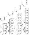
- FIG. 8 is a stretched sectional view through a rotor 20 shown.
- "Stretched cut” means that the poles 24 and 25 are linearly shown in a known manner.
- This pattern referred to below as basic pattern 100, is a self-contained component pattern that repeats itself on the circumference of the rotor 20 or in this rotor 20.
- This basic pattern 100 formed from the active bodies 55 of types B and A is repeated twice.
- This basic pattern can also be found, for example, in Table 4.1, Assembly Variant 8. But also, for example, in Table 1, Assembly Variant 24. It is therefore the case that in rotors 20 having numbers of poles 24, 25 that correspond to a multiple of two the basic pattern in the rotor is repeated at least twice on the circumference of the rotor 20.
- a rotor 20 is shown schematically having a number of poles of 6. Accordingly, the basic pattern 100 is repeated at least twice or three times.
- a basic pattern 100 of two different magnets A and B was repeated three times, a basic pattern 100, for example, twice in the arrangement ABB.
- the basic pattern 100 shown there consists of three directly successive active bodies 55 arranged in series of the materials B, A and A. This basic pattern can be found, for example, in Table 4.1, assembly variant 7.
- the basic pattern FIG. 9 can of course and readily be applied to an electric machine with 12 poles, so that repeat four basic pattern 100 on the circumference, see all in all the above-mentioned Table 4.1, component 7.
- a basic pattern 100 of four active bodies 55 of the types B and A is shown, the four active bodies 55 being composed according to the following types in this order and directly one after the other: BAAA.
- BAAA basic pattern
- Such a pattern can be found, for example, in Table 4.1, assembly variant 4, wherein in the example given there, due to the number of poles of 12, the basic pattern 100 is three times the circumference repeated. For an exemplary embodiment with 16 poles, see also Table 1, this basic pattern 100 is then repeated a total of four times, assembly variant 7.
- a rotor 20 is shown having 10 poles.
- the basic pattern 100 disclosed therein consists of the active bodies 55 already shown in the sequence BA, which repeats itself a total of five times on the circumference.
- a rotor 20 is shown, which carries active body 55 here, which form a basic pattern 100, which here consists of five different active bodies 55 in the order ABBBB. This basic pattern 100 repeats twice on the circumference.
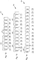
- a twelve-pole rotor 20 is shown, in which the basic pattern 100 is repeated three times on the circumference.
- the basic pattern 100 is here the order of active bodies 55 of the type ABBB. This basic pattern is shown in Table 4.1, line 16 or assembly variant 16.
- a fourteen-pole rotor 20 is shown in which the simple basic pattern 100, formed from the two active bodies 55 of the type BA, repeated a total of seven times on the circumference.
- FIG. 15 a sixteen-pole rotor 20 is shown, which has the simple basic pattern BA of two active bodies 55. Accordingly, this basic pattern repeats itself eight times on the circumference, see Table 1, assembly variant 24. In this table 1, the basic pattern 100 ABBA can be found, Table 1, assembly variant 20.
- FIG. 17 another variant of the basic pattern 100 is pre-ordered.
- this variant of the basic pattern also vacancies between two poles 24 and 25 play a role.
- the basic pattern 100 is formed of three active bodies 55 in the order of types ABB including a blank followed by the three active bodies 55.
- the basic pattern 100 shows at least one empty gap 21.
- FIG. 18 the situation of two different active bodies 55 is shown by way of example.
- the active body to the left is an active body of the type A
- the active body 55 to the right is of the type B.
- the representation is indeed shown in a development representation, so that a radius is not readily apparent.
- each active body 55 has a point 105, here even two points 105, which is at a maximum distance from the axis of rotation 80. Due to the positions of the active bodies 55 and the plate-shaped holding elements 60, it is clear that the maximum distance D1 of the point 105 of one active body 55 - type A - is greater than the maximum distance D2 of the point 105 of the other active body 55 - type B -.
- the active bodies 55 of the type A and B differ not only in the remanence R-A and R-B from each other but also in the specific electrical conductivity of their materials.
- the active bodies 55 with the lower specific electrical conductivity are arranged radially further out, while those with the higher specific electrical conductivity are arranged radially further inwards. This depends on the eddy current losses in the active bodies 55 associated with the conductivity. The better the specific electrical conductivity, the higher the eddy current losses and thus the heating of the corresponding active body 55.
- Active body 55 with the lower specific electrical conductivity are radially outward with the radially outwardly directed surface.
- the spatial shape of an active body 55 of a device 66 for compensation of stray flux differs from the spatial shape of an active body 55 of another technically different device 66 for compensation of stray flux.
- the distinction is based, for example, in volume, so that, for example, the active bodies 55 of type B have a smaller volume than the active bodies 55 of type A. This is because, for example, compare an arrangement as in FIG. 14 indicated that the poles 24 and 25 are not loaded too strong and symmetrical. If, for example, both active bodies 55 were the same size from their outer contours, but had a different density, for example, the active body 55 of type B would be two to two and a half times as heavy as an active body 55 of type A.
- the active body 55 with the remanence RA is a so-called ferrite magnet and the active body 55 with the remanence RB is a rare earth magnet.
- An active body 55 with the remanence RC can be, for example, a rare earth magnet.
- active bodies 55 may be, for example, cuboid and thereby have a square cross-section or be cuboid and thereby have a rectangular cross-section, be designed trapezoidal or have a cuboid shape, to which a triangular prism is integrally formed.
- materials for the active body 55 are, for example, permanent magnets made of ferrites (remanence between 0.2 to 0.48 Tesla), aluminum-nickel-cobalt (remanence between 0.5 Tesla to 1.3 Tesla), samarium cobalt (remanence between 0 , 8 Tesla to 1.2 Tesla), neodymium-iron-boron (remanence between 0.42 Tesla to 1.51 Tesla) in question.
- the ingredients mentioned for the respective magnetic material do not exclude that other substances can not be processed in these materials or their bodies.
- the terms just given are common names for such permanent magnets.
- the arrangement of the basic pattern 100 are provided for both right-handed and left-handed generators or electrical machines. Furthermore, the arrangement of the basic pattern 100 is independent of the position of the drive element (for example, pulley), ie at which end of the rotor shaft it is arranged.
- the drive element for example, pulley
Landscapes
- Engineering & Computer Science (AREA)
- Power Engineering (AREA)
- Iron Core Of Rotating Electric Machines (AREA)
- Permanent Field Magnets Of Synchronous Machinery (AREA)
Claims (15)
- Machine électrique (10), notamment générateur de courant alternatif, comprenant un stator (16) qui possède une surface (19) active du point de vue électromagnétique, comprenant un rotor (20) qui possède également une surface (26) active du point de vue électromagnétique, la surface (26) active du point de vue électromagnétique du rotor (20) se trouvant à l'opposé de la surface (19) active du point de vue électromagnétique du stator (16) en vue d'une interaction, le rotor (20) comprenant plusieurs pôles (24, 25) pouvant être polarisés différemment et des espaces intermédiaires (21) servant à la séparation des pôles-étant présents entre des pôles (24, 25) voisins pouvant être polarisés différemment, un dispositif (66) servant à la compensation du flux de dispersion avec un corps actif (55) étant respectivement disposé dans au moins deux espaces intermédiaires (21), caractérisée en ce qu'un dispositif (66) servant à la compensation du flux de dispersion avec un corps actif (55) est disposé dans un espace intermédiaire (21) et un dispositif (66) servant à la compensation du flux de dispersion avec un autre corps actif (55) est disposé dans un autre espace intermédiaire (21), les corps actifs (55) des différents dispositifs (66) possédant des rémanences (R-A, R-B, R-C) différentes.
- Machine électrique (10) selon la revendication 1, caractérisée en ce que l'un des dispositifs (66) servant à la compensation du flux de dispersion possède un corps actif (55) ayant une rémanence (R-A) et l'autre dispositif (66) servant à la compensation du flux de dispersion possède un corps actif (55) ayant une rémanence (R-B), la rémanence (R-B) étant supérieure à la rémanence (R-A).
- Machine électrique (10) selon la revendication 2, caractérisée en ce qu'un dispositif (66) supplémentaire servant à la compensation du flux de dispersion possède un corps actif (55) ayant une rémanence (R-C), la rémanence (R-C) étant supérieure à la rémanence (R-B).
- Machine électrique (10) selon la revendication 2 ou 3, caractérisée en ce que les corps actifs (55) possèdent des rémanences (R-A, R-B, R-C) qui sont comprises entre 0,2 T et 1,51 T.
- Machine électrique (10) selon l'une des revendications précédentes, caractérisée en ce que les dispositifs (66) servant à la compensation du flux de dispersion sont disposés dans le rotor (20) de telle sorte qu'un centre de gravité commun de tous les dispositifs (66) se trouve au total a) dans l'axe de rotation (80) et b) dans un arbre de rotor (27).
- Machine électrique (10) selon l'une des revendications précédentes, caractérisée en ce que la disposition des dispositifs (66) servant à la compensation du flux de dispersion dans le rotor (20) est symétrique, notamment à symétrie ponctuelle ou à symétrie en miroir.
- Machine électrique (10) selon l'une des revendications précédentes, caractérisée en ce que les dispositifs (66) techniquement différents servant à la compensation du flux de dispersion sont disposés dans le rotor (20) sous la forme d'un modèle de base (100) et ce modèle de base (100) se répètea) deux fois dans le cas de quatre pôles (24, 25) dans le rotor (20),b) deux ou trois fois dans le cas de six pôles (24, 25) dans le rotor (20),c) deux ou quatre fois dans le cas de huit pôles (24, 25) dans le rotor (20),d) deux ou cinq fois dans le cas de dix pôles (24, 25) dans le rotor (20),e) deux ou trois ou quatre ou six fois dans le cas de douze pôles (24, 25) dans le rotor (20),f) deux ou sept fois dans le cas de quatorze pôles (24, 25) dans le rotor (20),g) deux ou quatre ou huit fois dans le cas de seize pôles (24, 25) dans le rotor (20), en se suivant directement sur le pourtour du rotor (20).
- Machine électrique selon la revendication 6 ou les cas b) à g) de la revendication 7, caractérisée en ce que le modèle de base (100) possède au moins un espace intermédiaire vide (21).
- Machine électrique (10) selon l'une des revendications précédentes, caractérisée en ce que le corps actif (55) d'un dispositif (66) servant à la compensation du flux de dispersion possède un endroit (105) qui est éloigné au maximum de l'axe de rotation (80) et le corps actif (55) d'un autre dispositif (66), techniquement différent, servant à la compensation du flux de dispersion possède un endroit (105) qui est lui aussi éloigné au maximum de l'axe de rotation (80), un éloignement maximal (D1) de l'endroit (105) de l'un des corps actifs (55) étant supérieur à l'éloignement maximal (D2) de l'endroit (105) de l'autre corps actif (55).
- Machine électrique (10) selon la revendication 9, caractérisée en ce que le corps actif (55) du dispositif (66) servant à la compensation du flux de dispersion (55) dont l'endroit (105) éloigné au maximum de l'axe de rotation (80) est plus éloigné de l'axe de rotation (80) qu'un endroit (105) éloigné au maximum de l'axe de rotation (80) d'un autre corps actif (55) d'un autre dispositif (66) servant à la compensation du flux de dispersion possède un matériau magnétique qui présente une conductivité électrique plus faible que celle du matériau magnétique de l'autre corps actif.
- Machine électrique (10) selon l'une des revendications précédentes, caractérisée en ce que la structure dans l'espace d'un corps actif (55) d'un dispositif (66) servant à la compensation du flux de dispersion se différencie de la structure dans l'espace d'un corps actif (55) d'un autre dispositif (66) techniquement différent servant à la compensation du flux de dispersion.
- Machine électrique (10) selon l'une des revendications précédentes, caractérisée en ce qu'au moins un espace intermédiaire (21) ne contient aucun dispositif (66) servant à la compensation du flux de dispersion.
- Machine électrique (10) selon l'une des revendications précédentes, caractérisée en ce que les corps actifs (55) des dispositifs (66) techniquement différents servant à la compensation du flux de dispersion possèdent le même poids.
- Machine électrique (10) selon l'une des revendications précédentes, caractérisée en ce que le corps actif (55) ayant la rémanence (R-A) est un aimant en ferrite et le corps actif (55) ayant la rémanence (R-B) est un aimant en terre rare.
- Machine électrique (10) selon l'une des revendications 3 et 4, caractérisée en ce que le corps actif (55) ayant la rémanence (R-C) est un aimant en terre rare.
Applications Claiming Priority (2)
| Application Number | Priority Date | Filing Date | Title |
|---|---|---|---|
| DE102011085429A DE102011085429A1 (de) | 2011-10-28 | 2011-10-28 | Elektrische Maschine, insbesondere Wechselstromgenerator |
| PCT/EP2012/070411 WO2013060593A2 (fr) | 2011-10-28 | 2012-10-15 | Machine électrique, en particulier génératrice à courant alternatif |
Publications (3)
| Publication Number | Publication Date |
|---|---|
| EP2771965A2 EP2771965A2 (fr) | 2014-09-03 |
| EP2771965B1 true EP2771965B1 (fr) | 2016-12-14 |
| EP2771965B2 EP2771965B2 (fr) | 2020-01-08 |
Family
ID=47115852
Family Applications (1)
| Application Number | Title | Priority Date | Filing Date |
|---|---|---|---|
| EP12780461.5A Active EP2771965B2 (fr) | 2011-10-28 | 2012-10-15 | Machine électrique, en particulier génératrice à courant alternatif |
Country Status (4)
| Country | Link |
|---|---|
| EP (1) | EP2771965B2 (fr) |
| DE (1) | DE102011085429A1 (fr) |
| ES (1) | ES2619680T3 (fr) |
| WO (1) | WO2013060593A2 (fr) |
Citations (9)
| Publication number | Priority date | Publication date | Assignee | Title |
|---|---|---|---|---|
| JPS57101553A (en) | 1980-12-12 | 1982-06-24 | Hitachi Ltd | Rotary electric machine |
| EP0394528A1 (fr) | 1989-04-27 | 1990-10-31 | Siemens Aktiengesellschaft | Machine synchrone |
| US5543676A (en) | 1995-03-16 | 1996-08-06 | Ford Motor Company | Rotating electrical machine with magnetic inserts |
| US5838085A (en) | 1994-06-08 | 1998-11-17 | Precise Power Corporation | Versatile AC dynamo-electric machine |
| EP1089417A2 (fr) | 1999-09-30 | 2001-04-04 | Hitachi, Ltd. | Alternateur de véhicule automobile |
| US20050156479A1 (en) | 2004-01-19 | 2005-07-21 | Mitsubishi Denki Kabushiki Kaisha | Alternating-current dynamoelectric machine |
| US20060290232A1 (en) | 2005-06-24 | 2006-12-28 | Mitsubishi Denki Kabushiki Kaisha | Alternating-current dynamoelectric machine |
| EP1078438B1 (fr) | 1999-03-22 | 2007-02-28 | Valeo Equipements Electriques Moteur | Machine tournante comportant des aimants de compositions differentes |
| WO2011131871A1 (fr) | 2010-04-23 | 2011-10-27 | Valeo Equipements Electriques Moteur | Rotor de machine electrique tournante avec structures interpolaires |
Family Cites Families (12)
| Publication number | Priority date | Publication date | Assignee | Title |
|---|---|---|---|---|
| DE1209651B (de) * | 1964-04-28 | 1966-01-27 | Bosch Gmbh Robert | Sich selbst erregender Wechselstromerzeuger |
| US5780953A (en) | 1993-12-07 | 1998-07-14 | Nippondenso Co., Ltd. | Alternator |
| JPH1198787A (ja) | 1997-09-22 | 1999-04-09 | Hitachi Ltd | 車両用交流発電機 |
| US5965967A (en) * | 1998-07-06 | 1999-10-12 | Ford Global Technologies, Inc. | Rotor for an electrical machine |
| FR2784248B1 (fr) * | 1998-10-02 | 2000-12-22 | Valeo Equip Electr Moteur | Alternateur pour vehicule avec rattrapage de jeu sur les aimants interpolaires |
| US6603107B2 (en) | 2000-04-10 | 2003-08-05 | Mitsubishi Denki Kabushiki Kaisha | Image pickup device and portable telephone |
| US6359366B1 (en) * | 2000-05-09 | 2002-03-19 | Ford Global Technologies, Inc. | Hybrid permanent magnet/synchronous machines |
| FR2895165B1 (fr) * | 2005-12-21 | 2015-01-02 | Valeo Equip Electr Moteur | Rotor de machine electrique tournante comportant un element magnetique entre deux dents adjacentes |
| FR2899736B1 (fr) | 2006-04-10 | 2008-05-30 | Valeo Equip Electr Moteur | Rotor de machine electrique tournante comportant des gorges pour aimants |
| JP4692428B2 (ja) * | 2006-07-21 | 2011-06-01 | 株式会社デンソー | 車両用回転電機の回転子とその製造方法 |
| DE102007038668A1 (de) * | 2007-08-15 | 2009-02-26 | Klaus-Dieter Klement Verwaltungs Gmbh | Elektromotor, insbesondere Synchronmotor |
| JP4834712B2 (ja) * | 2008-10-15 | 2011-12-14 | 株式会社東芝 | モータ制御装置,モータ制御システム,洗濯機及び永久磁石モータの着磁方法 |
-
2011
- 2011-10-28 DE DE102011085429A patent/DE102011085429A1/de not_active Withdrawn
-
2012
- 2012-10-15 ES ES12780461.5T patent/ES2619680T3/es active Active
- 2012-10-15 WO PCT/EP2012/070411 patent/WO2013060593A2/fr not_active Ceased
- 2012-10-15 EP EP12780461.5A patent/EP2771965B2/fr active Active
Patent Citations (9)
| Publication number | Priority date | Publication date | Assignee | Title |
|---|---|---|---|---|
| JPS57101553A (en) | 1980-12-12 | 1982-06-24 | Hitachi Ltd | Rotary electric machine |
| EP0394528A1 (fr) | 1989-04-27 | 1990-10-31 | Siemens Aktiengesellschaft | Machine synchrone |
| US5838085A (en) | 1994-06-08 | 1998-11-17 | Precise Power Corporation | Versatile AC dynamo-electric machine |
| US5543676A (en) | 1995-03-16 | 1996-08-06 | Ford Motor Company | Rotating electrical machine with magnetic inserts |
| EP1078438B1 (fr) | 1999-03-22 | 2007-02-28 | Valeo Equipements Electriques Moteur | Machine tournante comportant des aimants de compositions differentes |
| EP1089417A2 (fr) | 1999-09-30 | 2001-04-04 | Hitachi, Ltd. | Alternateur de véhicule automobile |
| US20050156479A1 (en) | 2004-01-19 | 2005-07-21 | Mitsubishi Denki Kabushiki Kaisha | Alternating-current dynamoelectric machine |
| US20060290232A1 (en) | 2005-06-24 | 2006-12-28 | Mitsubishi Denki Kabushiki Kaisha | Alternating-current dynamoelectric machine |
| WO2011131871A1 (fr) | 2010-04-23 | 2011-10-27 | Valeo Equipements Electriques Moteur | Rotor de machine electrique tournante avec structures interpolaires |
Non-Patent Citations (1)
| Title |
|---|
| "terres rares", GUIDE DES AIMANTS ARELEC, 1996, pages 30,34,36, XP055417856 |
Also Published As
| Publication number | Publication date |
|---|---|
| EP2771965A2 (fr) | 2014-09-03 |
| EP2771965B2 (fr) | 2020-01-08 |
| WO2013060593A2 (fr) | 2013-05-02 |
| ES2619680T3 (es) | 2017-06-26 |
| WO2013060593A3 (fr) | 2014-05-15 |
| DE102011085429A1 (de) | 2013-05-02 |
Similar Documents
| Publication | Publication Date | Title |
|---|---|---|
| DE112018003438T5 (de) | Rotierende elektrische Maschine | |
| DE102018113266A1 (de) | Elektromotor mit eingebettetem dauermagnet | |
| DE112009002090T5 (de) | Drehende eletrische Maschine | |
| EP1145407A1 (fr) | Generateur a poles a griffes | |
| DE102008019734A1 (de) | Elektrische Maschine und Rotor für dieselbe | |
| EP3711143A1 (fr) | Rotor pour un moteur à flux axial, moteur à flux radial et moteur à flux transversal | |
| DE102015110652B4 (de) | Rotor-stator-anordnung für eine hybriderregte synchronmaschine und ein rotor dafür | |
| DE102012111930A1 (de) | Permanentmagnetläufer und mit dem Läufer versehener Elektromotor | |
| WO2012101083A2 (fr) | Machine synchrone à aimants permanents munie d'un rotor | |
| DE102006000455A1 (de) | Innenpermanentmagnetrotor und Innenpermanentmagnetmotor | |
| DE102007056116B4 (de) | Permanenterregte elektrische Maschine | |
| DE102012223701A1 (de) | Elektrische Maschine | |
| DE102012223711A1 (de) | Elektrische Maschine | |
| DE102014208344A1 (de) | Rotorblechpaket | |
| DE102007035321B4 (de) | Elektrische Maschine, vorzugsweise Generator, mit Hybriderreger | |
| DE102015212127A1 (de) | Permanent erregte elektrische Maschine mit optimierter Geometrie | |
| EP2319164B1 (fr) | Rotor pour une machine électrique à couple de détente réduit | |
| EP2771965B1 (fr) | Machine électrique, en particulier génératrice à courant alternatif | |
| DE102017101913A1 (de) | Elektromotor mit eingebettetem Dauermagnet | |
| EP1405389A1 (fr) | Machine a flux transversal excitee par aimant permanent | |
| DE102011085118A1 (de) | Halterung für elektrische Maschinen | |
| EP2705590B1 (fr) | Rotor pour une maschine à aimants permanents | |
| DE102008032214B4 (de) | Reluktanzmotor | |
| WO2011104265A2 (fr) | Moteur électrique à dispositif rotor, dispositif rotor à flux magnétique optimisé et procédé permettant de faire fonctionner le moteur électrique | |
| DE10262148B4 (de) | Hochpoliger, mehrphasiger Wechselstrommotoren mit transversaler Flussführung |
Legal Events
| Date | Code | Title | Description |
|---|---|---|---|
| PUAI | Public reference made under article 153(3) epc to a published international application that has entered the european phase |
Free format text: ORIGINAL CODE: 0009012 |
|
| 17P | Request for examination filed |
Effective date: 20140422 |
|
| AK | Designated contracting states |
Kind code of ref document: A2 Designated state(s): AL AT BE BG CH CY CZ DE DK EE ES FI FR GB GR HR HU IE IS IT LI LT LU LV MC MK MT NL NO PL PT RO RS SE SI SK SM TR |
|
| AX | Request for extension of the european patent |
Extension state: BA ME |
|
| R17P | Request for examination filed (corrected) |
Effective date: 20141117 |
|
| RBV | Designated contracting states (corrected) |
Designated state(s): AL AT BE BG CH CY CZ DE DK EE ES FI FR GB GR HR HU IE IS IT LI LT LU LV MC MK MT NL NO PL PT RO RS SE SI SK SM TR |
|
| DAX | Request for extension of the european patent (deleted) | ||
| REG | Reference to a national code |
Ref country code: DE Ref legal event code: R079 Ref document number: 502012009050 Country of ref document: DE Free format text: PREVIOUS MAIN CLASS: H02K0021040000 Ipc: H02K0001140000 |
|
| RIC1 | Information provided on ipc code assigned before grant |
Ipc: H02K 1/14 20060101AFI20160225BHEP Ipc: H02K 1/22 20060101ALI20160225BHEP Ipc: H02K 21/04 20060101ALI20160225BHEP |
|
| GRAP | Despatch of communication of intention to grant a patent |
Free format text: ORIGINAL CODE: EPIDOSNIGR1 |
|
| INTG | Intention to grant announced |
Effective date: 20160707 |
|
| GRAS | Grant fee paid |
Free format text: ORIGINAL CODE: EPIDOSNIGR3 |
|
| GRAA | (expected) grant |
Free format text: ORIGINAL CODE: 0009210 |
|
| AK | Designated contracting states |
Kind code of ref document: B1 Designated state(s): AL AT BE BG CH CY CZ DE DK EE ES FI FR GB GR HR HU IE IS IT LI LT LU LV MC MK MT NL NO PL PT RO RS SE SI SK SM TR |
|
| REG | Reference to a national code |
Ref country code: GB Ref legal event code: FG4D Free format text: NOT ENGLISH |
|
| REG | Reference to a national code |
Ref country code: CH Ref legal event code: EP |
|
| REG | Reference to a national code |
Ref country code: IE Ref legal event code: FG4D Free format text: LANGUAGE OF EP DOCUMENT: GERMAN |
|
| REG | Reference to a national code |
Ref country code: AT Ref legal event code: REF Ref document number: 854377 Country of ref document: AT Kind code of ref document: T Effective date: 20170115 |
|
| REG | Reference to a national code |
Ref country code: DE Ref legal event code: R096 Ref document number: 502012009050 Country of ref document: DE |
|
| PG25 | Lapsed in a contracting state [announced via postgrant information from national office to epo] |
Ref country code: LV Free format text: LAPSE BECAUSE OF FAILURE TO SUBMIT A TRANSLATION OF THE DESCRIPTION OR TO PAY THE FEE WITHIN THE PRESCRIBED TIME-LIMIT Effective date: 20161214 |
|
| REG | Reference to a national code |
Ref country code: LT Ref legal event code: MG4D |
|
| REG | Reference to a national code |
Ref country code: NL Ref legal event code: MP Effective date: 20161214 |
|
| PG25 | Lapsed in a contracting state [announced via postgrant information from national office to epo] |
Ref country code: NO Free format text: LAPSE BECAUSE OF FAILURE TO SUBMIT A TRANSLATION OF THE DESCRIPTION OR TO PAY THE FEE WITHIN THE PRESCRIBED TIME-LIMIT Effective date: 20170314 Ref country code: SE Free format text: LAPSE BECAUSE OF FAILURE TO SUBMIT A TRANSLATION OF THE DESCRIPTION OR TO PAY THE FEE WITHIN THE PRESCRIBED TIME-LIMIT Effective date: 20161214 Ref country code: LT Free format text: LAPSE BECAUSE OF FAILURE TO SUBMIT A TRANSLATION OF THE DESCRIPTION OR TO PAY THE FEE WITHIN THE PRESCRIBED TIME-LIMIT Effective date: 20161214 Ref country code: GR Free format text: LAPSE BECAUSE OF FAILURE TO SUBMIT A TRANSLATION OF THE DESCRIPTION OR TO PAY THE FEE WITHIN THE PRESCRIBED TIME-LIMIT Effective date: 20170315 |
|
| PG25 | Lapsed in a contracting state [announced via postgrant information from national office to epo] |
Ref country code: HR Free format text: LAPSE BECAUSE OF FAILURE TO SUBMIT A TRANSLATION OF THE DESCRIPTION OR TO PAY THE FEE WITHIN THE PRESCRIBED TIME-LIMIT Effective date: 20161214 Ref country code: RS Free format text: LAPSE BECAUSE OF FAILURE TO SUBMIT A TRANSLATION OF THE DESCRIPTION OR TO PAY THE FEE WITHIN THE PRESCRIBED TIME-LIMIT Effective date: 20161214 Ref country code: FI Free format text: LAPSE BECAUSE OF FAILURE TO SUBMIT A TRANSLATION OF THE DESCRIPTION OR TO PAY THE FEE WITHIN THE PRESCRIBED TIME-LIMIT Effective date: 20161214 |
|
| REG | Reference to a national code |
Ref country code: ES Ref legal event code: FG2A Ref document number: 2619680 Country of ref document: ES Kind code of ref document: T3 Effective date: 20170626 |
|
| PG25 | Lapsed in a contracting state [announced via postgrant information from national office to epo] |
Ref country code: NL Free format text: LAPSE BECAUSE OF FAILURE TO SUBMIT A TRANSLATION OF THE DESCRIPTION OR TO PAY THE FEE WITHIN THE PRESCRIBED TIME-LIMIT Effective date: 20161214 |
|
| PG25 | Lapsed in a contracting state [announced via postgrant information from national office to epo] |
Ref country code: CZ Free format text: LAPSE BECAUSE OF FAILURE TO SUBMIT A TRANSLATION OF THE DESCRIPTION OR TO PAY THE FEE WITHIN THE PRESCRIBED TIME-LIMIT Effective date: 20161214 Ref country code: EE Free format text: LAPSE BECAUSE OF FAILURE TO SUBMIT A TRANSLATION OF THE DESCRIPTION OR TO PAY THE FEE WITHIN THE PRESCRIBED TIME-LIMIT Effective date: 20161214 Ref country code: IS Free format text: LAPSE BECAUSE OF FAILURE TO SUBMIT A TRANSLATION OF THE DESCRIPTION OR TO PAY THE FEE WITHIN THE PRESCRIBED TIME-LIMIT Effective date: 20170414 Ref country code: SK Free format text: LAPSE BECAUSE OF FAILURE TO SUBMIT A TRANSLATION OF THE DESCRIPTION OR TO PAY THE FEE WITHIN THE PRESCRIBED TIME-LIMIT Effective date: 20161214 Ref country code: RO Free format text: LAPSE BECAUSE OF FAILURE TO SUBMIT A TRANSLATION OF THE DESCRIPTION OR TO PAY THE FEE WITHIN THE PRESCRIBED TIME-LIMIT Effective date: 20161214 |
|
| PG25 | Lapsed in a contracting state [announced via postgrant information from national office to epo] |
Ref country code: SM Free format text: LAPSE BECAUSE OF FAILURE TO SUBMIT A TRANSLATION OF THE DESCRIPTION OR TO PAY THE FEE WITHIN THE PRESCRIBED TIME-LIMIT Effective date: 20161214 Ref country code: BG Free format text: LAPSE BECAUSE OF FAILURE TO SUBMIT A TRANSLATION OF THE DESCRIPTION OR TO PAY THE FEE WITHIN THE PRESCRIBED TIME-LIMIT Effective date: 20170314 Ref country code: PL Free format text: LAPSE BECAUSE OF FAILURE TO SUBMIT A TRANSLATION OF THE DESCRIPTION OR TO PAY THE FEE WITHIN THE PRESCRIBED TIME-LIMIT Effective date: 20161214 Ref country code: PT Free format text: LAPSE BECAUSE OF FAILURE TO SUBMIT A TRANSLATION OF THE DESCRIPTION OR TO PAY THE FEE WITHIN THE PRESCRIBED TIME-LIMIT Effective date: 20170414 |
|
| REG | Reference to a national code |
Ref country code: DE Ref legal event code: R026 Ref document number: 502012009050 Country of ref document: DE |
|
| PLBI | Opposition filed |
Free format text: ORIGINAL CODE: 0009260 |
|
| 26 | Opposition filed |
Opponent name: VALEO EQUIPEMENTS ELECTRIQUES MOTEUR Effective date: 20170913 |
|
| PLAX | Notice of opposition and request to file observation + time limit sent |
Free format text: ORIGINAL CODE: EPIDOSNOBS2 |
|
| REG | Reference to a national code |
Ref country code: FR Ref legal event code: PLFP Year of fee payment: 6 |
|
| REG | Reference to a national code |
Ref country code: DE Ref legal event code: R081 Ref document number: 502012009050 Country of ref document: DE Owner name: SEG AUTOMOTIVE GERMANY GMBH, DE Free format text: FORMER OWNER: ROBERT BOSCH GMBH, 70469 STUTTGART, DE |
|
| PG25 | Lapsed in a contracting state [announced via postgrant information from national office to epo] |
Ref country code: DK Free format text: LAPSE BECAUSE OF FAILURE TO SUBMIT A TRANSLATION OF THE DESCRIPTION OR TO PAY THE FEE WITHIN THE PRESCRIBED TIME-LIMIT Effective date: 20161214 |
|
| REG | Reference to a national code |
Ref country code: ES Ref legal event code: PC2A Owner name: SEG AUTOMOTIVE GERMANY GMBH Effective date: 20180119 |
|
| PG25 | Lapsed in a contracting state [announced via postgrant information from national office to epo] |
Ref country code: SI Free format text: LAPSE BECAUSE OF FAILURE TO SUBMIT A TRANSLATION OF THE DESCRIPTION OR TO PAY THE FEE WITHIN THE PRESCRIBED TIME-LIMIT Effective date: 20161214 |
|
| PLBB | Reply of patent proprietor to notice(s) of opposition received |
Free format text: ORIGINAL CODE: EPIDOSNOBS3 |
|
| RAP2 | Party data changed (patent owner data changed or rights of a patent transferred) |
Owner name: SEG AUTOMOTIVE GERMANY GMBH |
|
| REG | Reference to a national code |
Ref country code: FR Ref legal event code: TP Owner name: SEG AUTOMOTIVE GERMANY GMBH, DE Effective date: 20180315 |
|
| PG25 | Lapsed in a contracting state [announced via postgrant information from national office to epo] |
Ref country code: MC Free format text: LAPSE BECAUSE OF FAILURE TO SUBMIT A TRANSLATION OF THE DESCRIPTION OR TO PAY THE FEE WITHIN THE PRESCRIBED TIME-LIMIT Effective date: 20161214 |
|
| REG | Reference to a national code |
Ref country code: CH Ref legal event code: PL |
|
| GBPC | Gb: european patent ceased through non-payment of renewal fee |
Effective date: 20171015 |
|
| REG | Reference to a national code |
Ref country code: IE Ref legal event code: MM4A |
|
| PG25 | Lapsed in a contracting state [announced via postgrant information from national office to epo] |
Ref country code: CH Free format text: LAPSE BECAUSE OF NON-PAYMENT OF DUE FEES Effective date: 20171031 Ref country code: LU Free format text: LAPSE BECAUSE OF NON-PAYMENT OF DUE FEES Effective date: 20171015 Ref country code: LI Free format text: LAPSE BECAUSE OF NON-PAYMENT OF DUE FEES Effective date: 20171031 Ref country code: GB Free format text: LAPSE BECAUSE OF NON-PAYMENT OF DUE FEES Effective date: 20171015 |
|
| REG | Reference to a national code |
Ref country code: BE Ref legal event code: MM Effective date: 20171031 |
|
| PG25 | Lapsed in a contracting state [announced via postgrant information from national office to epo] |
Ref country code: BE Free format text: LAPSE BECAUSE OF NON-PAYMENT OF DUE FEES Effective date: 20171031 |
|
| PG25 | Lapsed in a contracting state [announced via postgrant information from national office to epo] |
Ref country code: MT Free format text: LAPSE BECAUSE OF FAILURE TO SUBMIT A TRANSLATION OF THE DESCRIPTION OR TO PAY THE FEE WITHIN THE PRESCRIBED TIME-LIMIT Effective date: 20161214 |
|
| REG | Reference to a national code |
Ref country code: FR Ref legal event code: PLFP Year of fee payment: 7 |
|
| PG25 | Lapsed in a contracting state [announced via postgrant information from national office to epo] |
Ref country code: IE Free format text: LAPSE BECAUSE OF NON-PAYMENT OF DUE FEES Effective date: 20171015 |
|
| REG | Reference to a national code |
Ref country code: AT Ref legal event code: MM01 Ref document number: 854377 Country of ref document: AT Kind code of ref document: T Effective date: 20171015 |
|
| PG25 | Lapsed in a contracting state [announced via postgrant information from national office to epo] |
Ref country code: AT Free format text: LAPSE BECAUSE OF NON-PAYMENT OF DUE FEES Effective date: 20171015 |
|
| PGFP | Annual fee paid to national office [announced via postgrant information from national office to epo] |
Ref country code: ES Payment date: 20181123 Year of fee payment: 18 Ref country code: IT Payment date: 20181019 Year of fee payment: 7 |
|
| APBM | Appeal reference recorded |
Free format text: ORIGINAL CODE: EPIDOSNREFNO |
|
| APBP | Date of receipt of notice of appeal recorded |
Free format text: ORIGINAL CODE: EPIDOSNNOA2O |
|
| APAH | Appeal reference modified |
Free format text: ORIGINAL CODE: EPIDOSCREFNO |
|
| PG25 | Lapsed in a contracting state [announced via postgrant information from national office to epo] |
Ref country code: HU Free format text: LAPSE BECAUSE OF FAILURE TO SUBMIT A TRANSLATION OF THE DESCRIPTION OR TO PAY THE FEE WITHIN THE PRESCRIBED TIME-LIMIT; INVALID AB INITIO Effective date: 20121015 |
|
| APBU | Appeal procedure closed |
Free format text: ORIGINAL CODE: EPIDOSNNOA9O |
|
| PG25 | Lapsed in a contracting state [announced via postgrant information from national office to epo] |
Ref country code: CY Free format text: LAPSE BECAUSE OF NON-PAYMENT OF DUE FEES Effective date: 20161214 |
|
| PG25 | Lapsed in a contracting state [announced via postgrant information from national office to epo] |
Ref country code: MK Free format text: LAPSE BECAUSE OF FAILURE TO SUBMIT A TRANSLATION OF THE DESCRIPTION OR TO PAY THE FEE WITHIN THE PRESCRIBED TIME-LIMIT Effective date: 20161214 |
|
| PUAH | Patent maintained in amended form |
Free format text: ORIGINAL CODE: 0009272 |
|
| STAA | Information on the status of an ep patent application or granted ep patent |
Free format text: STATUS: PATENT MAINTAINED AS AMENDED |
|
| 27A | Patent maintained in amended form |
Effective date: 20200108 |
|
| AK | Designated contracting states |
Kind code of ref document: B2 Designated state(s): AL AT BE BG CH CY CZ DE DK EE ES FI FR GB GR HR HU IE IS IT LI LT LU LV MC MK MT NL NO PL PT RO RS SE SI SK SM TR |
|
| REG | Reference to a national code |
Ref country code: DE Ref legal event code: R102 Ref document number: 502012009050 Country of ref document: DE |
|
| PG25 | Lapsed in a contracting state [announced via postgrant information from national office to epo] |
Ref country code: TR Free format text: LAPSE BECAUSE OF FAILURE TO SUBMIT A TRANSLATION OF THE DESCRIPTION OR TO PAY THE FEE WITHIN THE PRESCRIBED TIME-LIMIT Effective date: 20161214 |
|
| PG25 | Lapsed in a contracting state [announced via postgrant information from national office to epo] |
Ref country code: AL Free format text: LAPSE BECAUSE OF FAILURE TO SUBMIT A TRANSLATION OF THE DESCRIPTION OR TO PAY THE FEE WITHIN THE PRESCRIBED TIME-LIMIT Effective date: 20161214 |
|
| PG25 | Lapsed in a contracting state [announced via postgrant information from national office to epo] |
Ref country code: ES Free format text: LAPSE BECAUSE OF FAILURE TO SUBMIT A TRANSLATION OF THE DESCRIPTION OR TO PAY THE FEE WITHIN THE PRESCRIBED TIME-LIMIT Effective date: 20200108 Ref country code: IT Free format text: LAPSE BECAUSE OF NON-PAYMENT OF DUE FEES Effective date: 20191015 |
|
| REG | Reference to a national code |
Ref country code: DE Ref legal event code: R082 Ref document number: 502012009050 Country of ref document: DE Representative=s name: DEHNSGERMANY PARTNERSCHAFT VON PATENTANWAELTEN, DE Ref country code: DE Ref legal event code: R082 Ref document number: 502012009050 Country of ref document: DE Representative=s name: DEHNS GERMANY PARTNERSCHAFT MBB, DE |
|
| PGFP | Annual fee paid to national office [announced via postgrant information from national office to epo] |
Ref country code: FR Payment date: 20221018 Year of fee payment: 11 |
|
| PG25 | Lapsed in a contracting state [announced via postgrant information from national office to epo] |
Ref country code: FR Free format text: LAPSE BECAUSE OF NON-PAYMENT OF DUE FEES Effective date: 20231031 |
|
| PGFP | Annual fee paid to national office [announced via postgrant information from national office to epo] |
Ref country code: DE Payment date: 20241018 Year of fee payment: 13 |