EP2772430A1 - Bras de flexion cruciforme d'une partie et procédé de fabrication d'un tel bras - Google Patents
Bras de flexion cruciforme d'une partie et procédé de fabrication d'un tel bras Download PDFInfo
- Publication number
- EP2772430A1 EP2772430A1 EP13400002.5A EP13400002A EP2772430A1 EP 2772430 A1 EP2772430 A1 EP 2772430A1 EP 13400002 A EP13400002 A EP 13400002A EP 2772430 A1 EP2772430 A1 EP 2772430A1
- Authority
- EP
- European Patent Office
- Prior art keywords
- flexbeam
- mould
- cruciform
- head
- rovings
- Prior art date
- Legal status (The legal status is an assumption and is not a legal conclusion. Google has not performed a legal analysis and makes no representation as to the accuracy of the status listed.)
- Granted
Links
Images

Classifications
-
- B—PERFORMING OPERATIONS; TRANSPORTING
- B64—AIRCRAFT; AVIATION; COSMONAUTICS
- B64C—AEROPLANES; HELICOPTERS
- B64C27/00—Rotorcraft; Rotors peculiar thereto
- B64C27/04—Helicopters
-
- B—PERFORMING OPERATIONS; TRANSPORTING
- B64—AIRCRAFT; AVIATION; COSMONAUTICS
- B64C—AEROPLANES; HELICOPTERS
- B64C27/00—Rotorcraft; Rotors peculiar thereto
- B64C27/32—Rotors
- B64C27/33—Rotors having flexing arms
-
- Y—GENERAL TAGGING OF NEW TECHNOLOGICAL DEVELOPMENTS; GENERAL TAGGING OF CROSS-SECTIONAL TECHNOLOGIES SPANNING OVER SEVERAL SECTIONS OF THE IPC; TECHNICAL SUBJECTS COVERED BY FORMER USPC CROSS-REFERENCE ART COLLECTIONS [XRACs] AND DIGESTS
- Y10—TECHNICAL SUBJECTS COVERED BY FORMER USPC
- Y10T—TECHNICAL SUBJECTS COVERED BY FORMER US CLASSIFICATION
- Y10T29/00—Metal working
- Y10T29/49—Method of mechanical manufacture
- Y10T29/49316—Impeller making
- Y10T29/4932—Turbomachine making
Definitions
- the invention is related to a partly cruciform flexbeam of a bearingless main rotor system of a helicopter with the features of the preamble of claim 1 and to a method of manufacturing such a partly cruciform flexbeam with the features of the preamble of claim 5.
- the rotor blades of a helicopter are deflected in various directions and are thereby subjected to high loads in these various directions.
- the rotor blades must be designed to withstand these high loads while still providing the required flexibility or articulation to allow the blades to carry out flapping, lead-lag oscillating and pitch angle variation movements.
- a rotor blade of a bearingless rotor includes a structural element known as a flexbeam at the inner end of the blade for connection to the rotor head.
- the flexbeam supports and transmits the centrifugal forces of the blade into the rotor hub.
- the flexbeam includes at least portions or regions that are flexural and torsion soft or flexible to allow the blade to undergo the above mentioned movements in a flapping direction, a lead-lag direction and in a pitch angle direction.
- the torsion soft portion of the flexbeam is arranged within a torsion stiff control cuff or torque tube, transmitting the pitch angle control movements to the lift-generating airfoil blade portion of the rotor blade.
- the airfoil blade typically extends from the outboard end of the control cuff to the outermost end of the rotor blade, i.e. the blade tip.
- flexbeams are made of composite materials.
- the flexbeam is subject to high technical and mechanical demands, because it must reliably carry and transmit the substantially high centrifugal forces resulting during rotation of the rotor blade and it must reliably carry and transmit all bending moments from flapping and lead lag movements of the rotor blade.
- the rotor blade has a longitudinal main load axis next to 25% of the average airfoil chord of the blade profile, said main load axis being in practice essentially identical with the pitch axis of said rotor blade.
- said longitudinal main load axis next to 25% of the average airfoil chord of the blade profile corresponds to a longitudinal middle axis of the flexbeam.
- An efficient transmission of the lead lag moments from the airfoil blade into the flexbeam/control cuff and the lift-generating airfoil blade allows high damping effectiveness of the lead lag damping elements at the rotor hub and thus allows smaller, lighter and cheaper damping elements.
- An efficient transmission of the lead lag moments needs a flexbeam with a distinct lead lag joint. Such a distinct lead lag joint leads to a cross section of the flexbeam at the releasable junction between the flexbeam and the lift-generating airfoil blade that is high and slim whereas the lead lag joint of the flexbeam needs to be large and low towards the rotor hub.
- a continuous geometry of the flexbeam from the releasable junction with the lift-generating airfoil blade to the releasable junction with the rotor hub is varying along the longitudinal middle axis of the flexbeam and said continuous geometry of the flexbeam is therefore complicated and a challenge with regard to production of the flexbeam.
- the high cross section of the flexbeam at the releasable junction between the flexbeam and the lift-generating airfoil blade causes relatively high aerodynamic resistance and thus a high need of performance of the main rotor system.
- the document US 5738494 A discloses an optimized composite flexbeam having a plurality of adjoining regions including a hub attachment region, a blade attachment region, a pitch region, an outboard transition region disposed between and adjoining the pitch region and blade attachment regions, and an inboard transition region disposed between and adjoining the pitch and hub attachment regions.
- the inboard transition region includes a first transition subregion and a second transition subregion wherein the second transition subregion defines a width conic and a critical width transition subregion.
- the first and second inboard transition regions are composed of a combination of unidirectional and off-axis composite materials wherein the off-axis composite material defines a percentage of off-axis composite material and wherein the percentage in the critical transition subregion is defined by an optimized curve.
- the document EP 0315962 A2 discloses a helicopter rotor blade supported by a flexbeam to be rotatable about an axis of rotation, in which a pitching motion thereof is allowable.
- the rotor blade is provided with a device for changing the pitch and damping the lead-lag motion thereof.
- the device comprises a bushing in a hole formed at the inboard end of the flexbeam, an elastomeric pivot loosely fitted in the bushing, elastomeric dampers of cylindrical shape mounted on the upper and lower surfaces of the flexbeam and coupled with the upper and lower ends of the elastomeric pivot by means of nuts, and torque arms extending through the bushing and the elastomeric dampers and having the central portion thereof connected to central shafts of the elastomeric pivots.
- Each of the pitch sleeves has both ends outwardly projecting beyond the elastomeric dampers and secured to a pitch sleeve which encloses the flexbeam. Therefore, the relative position between the pitch sleeve and the elastomeric pivot does not change even when lead-lag motion is imparted to the rotor blade.
- US 5096380 A discloses a flexbeam for a bearingless helicopter rotor with a composite beam, composed of unidirectional fibers bound in an epoxy matrix, having ribs, composed of unidirectional fibers bound in a urethane matrix, bonded to each horizontal face at the section of the beam which accommodates lead-lag torsion.
- the flexbeams of the state of the art are relatively long with simple cross sections to allow simple tools for production at the cost of efficient lead lad kinematics.
- the solution is provided with a partly cruciform flexbeam of a bearingless main rotor system of a helicopter with the features of claim 1 of the invention and with a method of manufacturing such a partly cruciform flexbeam with the features of claim 5 of the invention.
- a bearingless main rotor system of a helicopter is provided with a hub drive and an airfoil blade and a partly cruciform flexbeam as a link between said hub drive and said airfoil blade.
- Said partly cruciform flexbeam comprises a flexbeam head with a flat bearing laminate at one end and a root end opposed to said flexbeam head. Said root end is adapted for releasable connection to the hub drive and said flexbeam head is adapted for releasable connection to the airfoil blade.
- a flexbeam body is between said flexbeam head and said root end.
- Said flexbeam body is torsion soft with a substantially cruciform cross section of bars and fillets.
- Said bars are integral with and essentially perpendicular to said fillets and said bars are in line with said flexbeam head.
- Said flexbeam body is an assembly of four substructures, each with one bar integral with one essentially perpendicular fillet.
- Said four substructures are assembled along said longitudinal middle axis of the flexbeam with the respective bars and fillets pointing outward to result in said substantially cruciform, symmetric cross section with separations at least along said fillets.
- Said fillets and said bars are composed of a plurality of rovings.
- Said plurality of rovings extend all along the partly cruciform flexbeam from the root end to the entire flexbeam head or extend from at least beyond the separations along said fillets of the flexbeam body across said entire flexbeam head.
- At least two L-shaped integral tissue layers are provided extending from in between the flexbeam body up to an entire width of the flexbeam head with the rovings in between.
- the torsion soft flexbeam allows the flexbeam to be as short as possible, i. e.
- the torsion soft flexbeam allows good lead lag kinematics.
- said rovings from the fillet and the bar are scarfed or hafted towards said entire flexbeam head for improved adhesion of the flat bearing laminate in the flexbeam head.
- said at least two L-shaped integral tissue layers are alternating with the rovings of the flexbeam head for distribution of the loads into the flexbeam body by means of the rovings to reduce tensions at the interfaces of the layers.
- said at least two L-shaped integral tissue layers are formed integrally for high stiffness.
- a method of manufacturing a partly cruciform flexbeam of a bearingless main rotor system of a helicopter comprises a cruciform flexbeam body, a flat flexbeam head and a root end.
- Said method comprises the following steps: Providing at least two L-shaped integral tissue layers extending into the flexbeam body and up to the entire length and width of the flat flexbeam head. Providing four mould quarters, each with a mould for a bar and with a mould for a fillet of the cruciform flexbeam body.
- each of said four mould quarters for a bar is integral and essentially perpendicular to said mould for a fillet and said mould for a bar is essentially in line with said flat flexbeam head.
- Said pairs of mould quarters are joint along said inserted fillets with means to provide said separations in between the fillets along the cruciform flexbeam body and to respectively provide a common mould for the bars of a half of the cruciform flexbeam body.
- Rovings are inserted respectively in the common mould for the bars of each of said pairs of joint mould quarters to respectively mould the bars of the halves of the cruciform flexbeam body.
- Scarfing or hafting respectively the rovings of the fillets and the bars of said pairs of joint mould quarters to layers covering up to the entire width of the flexbeam head and inserting alternately the L-shaped integral tissue layers between the scarfed rovings of the fillets and bars of each of said pairs of joint mould quarters.
- two of said pairs of mould quarters are joint along the bars of said flexbeam body and along the rovings from said bars and/or fillets and/or L-shaped integral tissue layers of said flexbeam head in said respectively joint pairs of mould quarters.
- the inventive method allows production of the inventive flexbeam with separations along at least the fillets for adjustable torsion softness of the cruciform flexbeam body and subsequently for improved lead lag kinematics at low aerodynamic resistance.
- supplemental separations are provided in between the bars along the cruciform flexbeam body to further optimize torsion softness of the flexbeam.
- supplemental rovings are provided for completion of layers at the flexbeam head and to further reduce tensions at the interfaces of the layers and for more flexibility with regard to the geometry of the flexbeam head and/or flexbeam body.
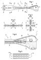
- a partly cruciform flexbeam 1 of a bearingless main rotor system (not shown) of a helicopter is made of composite material.
- the partly cruciform flexbeam 1 comprises a flexbeam head 2 of a flat bearing laminate at one end and a root end 3 opposed to said flexbeam head 2.
- Said root end 3 is provided with two borings 4 for bolts (not shown) for a releasable connection to a hub drive (not shown) and said flexbeam head 2 is provided with a further boring 5 for a bolt (not shown) for a releasable connection to an airfoil blade (not shown).
- a torsion soft flexbeam body 6 between said flexbeam head 2 and said root end 3 has a substantially cruciform cross section of bars 7 and fillets 8, said torsion softness without centrifugal forces being smaller than 3Nm/m°.
- Said bars 7 are integral with and essentially perpendicular to said fillets 8 and said bars 7 are in line with said flat flexbeam head 2.
- the cross section of the flexbeam body 6 towards said root end 3 is large between 120 - 250 mm and low between 10 - 40 mm while the cross section of the flexbeam body 6 towards said flexbeam head 2 is high between 60 - 120 mm and small between 40 - 90 mm.
- the cross sections of the partly cruciform flexbeam 1 vary continuously towards said flat flexbeam head 2 and said root end 3 along the cruciform flexbeam body 6.
- Said flexbeam body 6 is assembled of four bars 7 and four fillets 8 by aligning said four bars 7 along their respective faces to each other and said four fillets 8 along their respective faces to each other to said substantially cruciform cross section along a longitudinal middle axis 27 of the partly cruciform flexbeam 1.
- Each of the four bars 7 and four fillets 8 of said flexbeam body 6 have respectively essentially rectangular cross sections towards said root end 3 while each of the four bars 7 and four fillets 8 towards said flexbeam head 2 have respectively essentially small rectangular cross sections 28 next to the longitudinal middle axis 27 of said substantially cruciform cross section and widened quadrilateral cross sections 29 towards their respective peripheries.
- Central separations 30 are in between each of the widened quadrilateral cross sections of said fillets 8 and said bars 7 from the respective peripheries towards said longitudinal middle axis 27 of said flexbeam body 6.
- the cruciform cross section is essentially symmetric with regard to a plane of contact between the bars 7 and symmetric with regard to a plane of contact between the fillets 8.
- Said fillets 8 and said bars 7 are composed of a plurality of rovings 9, said plurality of rovings 9 extending all along from the root end 3 to the flexbeam head 2 along said flexbeam body 6. From said central separations 30 said fillets 8 further diverge from each other and turn towards said flexbeam head 2 in a transition area 26 between flexbeam body 6 and said flexbeam head 2.
- the plurality of rovings 9 essentially comprises unidirectional fibers.
- the rovings 9 of the fillets 8 and the bars 7 extend beyond the cruciform flexbeam body 6 and are respectively scarfed or hafted to layers covering at least partly the flexbeam head 2.
- Supplemental rovings are provided for completion of the layers in the flexbeam head 2, with some of said supplemental rovings extending along the rovings 9 into the flexbeam body 6 while remaining in the plane of the flexbeam head 2.
- the flexbeam head 2 of flat bearing laminate is composed of the layers of the unidirectional rovings 9 with L-shaped tissue layers 10 in between.
- Said L-shaped tissue layers 10 are integrally formed covering the entire length along the longitudinal middle axis 27 and up to the entire width of the flexbeam head 2.
- Said L-shaped tissue layers 10 extend with an essentially rectangular part into the flexbeam body 6 while remaining in the plane of the flexbeam head 2.
- Said L-shaped tissue layers 10 extend differently along the width of the flat bearing head 2 and differently along the essentially rectangular part into the flexbeam body 6 resulting in a scale-type arrangement of rovings 9, supplemental rovings and L-shaped tissue layers 10.
- Fig. 6 corresponding features are referred to with the references of Fig. 1 - 5 .
- four mould quarters 11 - 14 are provided, each with a mould for a bar 7 and with a mould for a fillet 8 of the cruciform flexbeam body 6.
- Said mould of each of said four mould quarters 11 - 14 for a bar 7 is integral and essentially perpendicular to said mould for a fillet 8 and said mould for a bar 7 is essentially in line with said flat flexbeam head 2.
- a pair of mould quarters 11 - 12 is held by screws 15, 16 in a top casing 17 and a further pair of mould quarters 13 - 14 is held by screws 18 - 20 in a bottom casing 21.
- Said four mould quarters 11 - 14 are assembled with their respective moulds for bars 7 directed towards each other and with their respective moulds for fillets 8 directed towards each other, providing at the interface of said assembly an open space with outer peripheries corresponding respectively to the bars 7 and fillets 8 of the cruciform cross sections for flexbeam body 6 shown in Fig. 2, 3 .
- Separation means 22 - 25 are provided between the four moulds 11 - 14 said separation means 22 - 25 projecting from outside centrally into the open space.
- the flat flexbeam head 2 and the root end 3 L-shaped integral tissue layers 10 are provided, said L-shaped integral tissue layers 10 corresponding to the entire length and up to the entire width of the flat flexbeam head 2.
- the rovings 9 with a length allowing coverage from at least beyond the separations along said fillets 8 of the flexbeam body 6 across said entire flexbeam head 2. Said rovings 9 are inserted into pairs of said still separated mould quarters 11 - 14 to respectively mould the two fillets 8 of a half of the cruciform flexbeam body 6.
- Said pairs of mould quarters 11 - 14 are respectively joint along said inserted fillets 8 with said separation means 22, 24 in between the fillets 8 along the longitudinal middle axis 27 of the cruciform flexbeam body 6 to respectively provide a common mould of a pair of mould quarters 11 - 14 for the bars 7 of said halves of the cruciform flexbeam body 6.
- Rovings 9 are respectively inserted with the direction of the longitudinal middle axis 27 in the common mould of a pair of mould quarters 11 - 14 for the bars 7 of each of said pairs of joint mould quarters 11 - 14 to respectively mould the bars 7 integral and perpendicular to the fillets 8 of the halves already moulded for the cruciform flexbeam body 6.
- Respectively two of said pairs of joint mould quarters 11 - 14 are joint along said bars 7 of said flexbeam body 6 and at the flexbeam head 2 along said scarfed rovings 9 from said bars 7 and/or said fillets 8 from said flexbeam body 6 and/or said intermediate L-shaped integral tissue layers 10 of said flexbeam head 2 in said respectively joint pairs of mould quarters 11 - 14.
- each of the mould quarters 11 - 14 provide one quarter of the partly cruciform flexbeam 1 with each of said quarters having a bar 7 and a fillet 8 of the cruciform flexbeam body 6 along the longitudinal middle axis 27 between the flexbeam head 2 and the root end 3.
- the rovings 9 of the fillets 8 and the bars 7 of each of said pairs of joint mould quarters 11 - 14, extending beyond the cruciform flexbeam body 6 are respectively scarfed or hafted to layers covering differently the flexbeam head 2.
- the L-shaped integral tissue layers 10 inserted alternately between the scarfed rovings 9 of the fillets 8 and bars 7 cover differently the flexbeam head 2.
- the L-shaped integral tissue layers 10 and the scarfed rovings 9 form the flexbeam head 2 and the flexbeam body 6 to different heights along the flexbeam 1.
- Reference List 1 flexbeam 2 flexbeam head 3 root end 4 boring 5 further boring 6 flexbeam body 7 bars 8 fillets 9 rovings 10 layers of tissue 11 - 14 mould quarters 15, 16 screws 17 top casing 18 - 20 screws 21 bottom casing 22 - 25 separation means 26 transition area 27 longitudinal middle axis 28 rectangular cross section 29 quadrilateral cross sections 30 central separations
Landscapes
- Engineering & Computer Science (AREA)
- Mechanical Engineering (AREA)
- Aviation & Aerospace Engineering (AREA)
- Wind Motors (AREA)
Priority Applications (2)
| Application Number | Priority Date | Filing Date | Title |
|---|---|---|---|
| EP13400002.5A EP2772430B1 (fr) | 2013-02-27 | 2013-02-27 | Bras de flexion cruciforme d'une partie et procédé de fabrication d'un tel bras |
| US14/190,546 US9623963B2 (en) | 2013-02-27 | 2014-02-26 | Partly cruciform flexbeam and method of manufacturing such a flexbeam |
Applications Claiming Priority (1)
| Application Number | Priority Date | Filing Date | Title |
|---|---|---|---|
| EP13400002.5A EP2772430B1 (fr) | 2013-02-27 | 2013-02-27 | Bras de flexion cruciforme d'une partie et procédé de fabrication d'un tel bras |
Publications (2)
| Publication Number | Publication Date |
|---|---|
| EP2772430A1 true EP2772430A1 (fr) | 2014-09-03 |
| EP2772430B1 EP2772430B1 (fr) | 2016-06-29 |
Family
ID=48463905
Family Applications (1)
| Application Number | Title | Priority Date | Filing Date |
|---|---|---|---|
| EP13400002.5A Active EP2772430B1 (fr) | 2013-02-27 | 2013-02-27 | Bras de flexion cruciforme d'une partie et procédé de fabrication d'un tel bras |
Country Status (2)
| Country | Link |
|---|---|
| US (1) | US9623963B2 (fr) |
| EP (1) | EP2772430B1 (fr) |
Families Citing this family (5)
| Publication number | Priority date | Publication date | Assignee | Title |
|---|---|---|---|---|
| US9051047B2 (en) * | 2012-11-12 | 2015-06-09 | Sikorsky Aircraft Corporation | Flexbeam rotor attachment to rotor blade |
| EP2772430B1 (fr) * | 2013-02-27 | 2016-06-29 | AIRBUS HELICOPTERS DEUTSCHLAND GmbH | Bras de flexion cruciforme d'une partie et procédé de fabrication d'un tel bras |
| WO2015200757A1 (fr) * | 2014-06-27 | 2015-12-30 | Sikorsky Aircraft Corporation | Élément de fixation de plaque de flexion destiné à un ensemble rotor |
| CN112224404A (zh) * | 2020-10-16 | 2021-01-15 | 中国直升机设计研究所 | 一种用于可折叠无轴承旋翼的袖套构型 |
| CN113719519B (zh) * | 2021-08-18 | 2022-07-05 | 中国商用飞机有限责任公司北京民用飞机技术研究中心 | 一种复合材料与金属接头连接的杆件结构 |
Citations (6)
| Publication number | Priority date | Publication date | Assignee | Title |
|---|---|---|---|---|
| EP0019041A1 (fr) * | 1979-04-28 | 1980-11-26 | Messerschmitt-Bölkow-Blohm Gesellschaft mit beschränkter Haftung | Rotor non-articulé |
| US4427340A (en) | 1982-06-24 | 1984-01-24 | Bell Helicopter Textron Inc. | Soft inplane bearingless helicopter rotor |
| US4650401A (en) * | 1983-04-07 | 1987-03-17 | Mcdonnell Douglas Helicopter Company | Flat strap cruciform flexure for helicopter rotor systems |
| EP0315962A2 (fr) | 1987-11-10 | 1989-05-17 | Fuji Jukogyo Kabushiki Kaisha | Système pour amortir le mouvement en traînée des pales de rotor d'un hélicoptère |
| US5096380A (en) | 1990-05-03 | 1992-03-17 | United Technology Corporation | Composite flexbeam for a bearingless helicopter rotor |
| US5738494A (en) | 1996-07-18 | 1998-04-14 | Sikorsky Aircraft Corporation | Optimized composite flexbeam for helicopter rotors |
Family Cites Families (20)
| Publication number | Priority date | Publication date | Assignee | Title |
|---|---|---|---|---|
| US3261407A (en) * | 1964-08-05 | 1966-07-19 | Lockheed Aircraft Corp | Helicopter rotor system |
| US3791234A (en) * | 1970-05-18 | 1974-02-12 | Lockheed Aircraft Corp | A retention member |
| US3695779A (en) * | 1970-05-18 | 1972-10-03 | Lockheed Aircraft Corp | Rotor system including a blade retention member |
| FR2574752B1 (fr) * | 1984-12-19 | 1987-02-20 | Aerospatiale | Pale pour rotor d'helicoptere en materiau composite multilongeron a caissons de torsion et son procede de fabrication |
| US4746272A (en) * | 1986-07-23 | 1988-05-24 | United Technologies Corporation | Lobed composite flexbeam |
| US4898515A (en) * | 1986-07-23 | 1990-02-06 | United Technologies Corporation | External wrap of composite flexbeam |
| JP2583259B2 (ja) * | 1988-01-08 | 1997-02-19 | 富士重工業株式会社 | ヘリコプタ用フレックスビーム |
| JPH085437B2 (ja) * | 1990-04-27 | 1996-01-24 | 防衛庁技術研究本部長 | 回転翼航空機用の無関節ハブ構造 |
| US5358381A (en) * | 1993-03-19 | 1994-10-25 | Bell Helicopter Textron Inc. | Yoke for helicopter rotor systems |
| DE19620427C1 (de) * | 1996-05-21 | 1997-06-12 | Eurocopter Deutschland | Rotorblattanschluß |
| US6375426B1 (en) * | 1999-09-28 | 2002-04-23 | Bell Helicopter Textron Inc. | Protective edge members for composite flexures |
| US6708921B2 (en) * | 2001-04-20 | 2004-03-23 | Bell Helicopter Textron, Inc. | Composite flapping flexure |
| EP2246259B1 (fr) * | 2009-04-29 | 2012-12-12 | Eurocopter Deutschland GmbH | Aile de rotor avec élément integral de transmission de tension et de couple et son procédé de fabrication |
| EP2246256B1 (fr) * | 2009-04-29 | 2012-10-24 | Eurocopter Deutschland GmbH | Élément de transmission de couple de tension pour pale de rotor anticouple et son procédé de fabrication |
| US8662847B2 (en) * | 2010-10-11 | 2014-03-04 | Eurocopter Deutschland Gmbh | Rotor blade with control tube |
| US9457897B2 (en) * | 2013-02-27 | 2016-10-04 | Bell Helicopter Textron Inc. | Rotor system shear bearing |
| EP2772430B1 (fr) * | 2013-02-27 | 2016-06-29 | AIRBUS HELICOPTERS DEUTSCHLAND GmbH | Bras de flexion cruciforme d'une partie et procédé de fabrication d'un tel bras |
| EP2783981B1 (fr) * | 2013-03-28 | 2017-03-15 | AIRBUS HELICOPTERS DEUTSCHLAND GmbH | Barre de matériau matriciel composite |
| US9499262B2 (en) * | 2013-08-02 | 2016-11-22 | Bell Helicopter Textron Inc. | Composite flexure for tiltrotor rotor system |
| EP2899121B1 (fr) * | 2014-01-22 | 2016-11-16 | AIRBUS HELICOPTERS DEUTSCHLAND GmbH | Unité de flexion pour rotor à pales multiples sans palier ou sans palier et charnière et aéronef à voilure tournante |
-
2013
- 2013-02-27 EP EP13400002.5A patent/EP2772430B1/fr active Active
-
2014
- 2014-02-26 US US14/190,546 patent/US9623963B2/en active Active
Patent Citations (6)
| Publication number | Priority date | Publication date | Assignee | Title |
|---|---|---|---|---|
| EP0019041A1 (fr) * | 1979-04-28 | 1980-11-26 | Messerschmitt-Bölkow-Blohm Gesellschaft mit beschränkter Haftung | Rotor non-articulé |
| US4427340A (en) | 1982-06-24 | 1984-01-24 | Bell Helicopter Textron Inc. | Soft inplane bearingless helicopter rotor |
| US4650401A (en) * | 1983-04-07 | 1987-03-17 | Mcdonnell Douglas Helicopter Company | Flat strap cruciform flexure for helicopter rotor systems |
| EP0315962A2 (fr) | 1987-11-10 | 1989-05-17 | Fuji Jukogyo Kabushiki Kaisha | Système pour amortir le mouvement en traînée des pales de rotor d'un hélicoptère |
| US5096380A (en) | 1990-05-03 | 1992-03-17 | United Technology Corporation | Composite flexbeam for a bearingless helicopter rotor |
| US5738494A (en) | 1996-07-18 | 1998-04-14 | Sikorsky Aircraft Corporation | Optimized composite flexbeam for helicopter rotors |
Non-Patent Citations (1)
| Title |
|---|
| BUCHS W ET AL: "STRUCTURAL DESIGN AND ANALYSIS ASPECTS OF COMPOSITE HELICOPTER COMPONENTS", VERTICA, PERGAMON PRESS, GB, vol. 11, no. 3, 1987, pages 407 - 424, XP002060956 * |
Also Published As
| Publication number | Publication date |
|---|---|
| EP2772430B1 (fr) | 2016-06-29 |
| US9623963B2 (en) | 2017-04-18 |
| US20140241885A1 (en) | 2014-08-28 |
Similar Documents
| Publication | Publication Date | Title |
|---|---|---|
| US9714579B2 (en) | Connection joint for attaching an airfoil blade to a helicopter's bearingless main rotor | |
| US9718542B2 (en) | Blade attachment for a bearingless rotor of a helicopter | |
| EP2832640B1 (fr) | Flexion composite pour système de rotor basculant | |
| US10689104B2 (en) | Tail rotor integrated damper attachment | |
| US20120087797A1 (en) | Rotor blade with control tube | |
| US9623963B2 (en) | Partly cruciform flexbeam and method of manufacturing such a flexbeam | |
| JPS59199397A (ja) | 複ブレ−ド式プロペラおよびそのブレ−ドならびにこのブレ−ドの製造方法 | |
| US9469399B2 (en) | Separable blade attachment for a bearingless rotor of a helicopter | |
| US10336445B2 (en) | High flapping yoke hub assembly using a cylindrical elastomeric attachment to avoid holes | |
| US10759529B2 (en) | Rotor blade coupling device of a rotor head for a rotorcraft | |
| EP2653385B1 (fr) | Fixation de pale aérodynamique pour un rotor sans palier d'un hélicoptère | |
| US9555880B2 (en) | Flexbeam rotor | |
| EP2772431B1 (fr) | Palier de cisaillement de système de rotor | |
| EP2457830B1 (fr) | Connexion d'une aube avec le moyeu du rotor | |
| EP2783981B1 (fr) | Barre de matériau matriciel composite | |
| RU2182100C2 (ru) | Воздушный винт | |
| US20130034443A1 (en) | Planar flexbeam unit | |
| CN102452477B (zh) | 由纤维加固复合材料制成的转子叶片及其生产方法 | |
| KR20120037195A (ko) | 섬유 강화 복합 재료로 만든 로터 블레이드 및 그 제조 방법 | |
| US12246825B2 (en) | Blade provided with a root comprising an integrated pitch attachment and two integrated damper attachments, and a rotor provided with such a blade | |
| KR101460291B1 (ko) | 평면형 플렉스빔 유닛 |
Legal Events
| Date | Code | Title | Description |
|---|---|---|---|
| PUAI | Public reference made under article 153(3) epc to a published international application that has entered the european phase |
Free format text: ORIGINAL CODE: 0009012 |
|
| 17P | Request for examination filed |
Effective date: 20130227 |
|
| AK | Designated contracting states |
Kind code of ref document: A1 Designated state(s): AL AT BE BG CH CY CZ DE DK EE ES FI FR GB GR HR HU IE IS IT LI LT LU LV MC MK MT NL NO PL PT RO RS SE SI SK SM TR |
|
| AX | Request for extension of the european patent |
Extension state: BA ME |
|
| R17P | Request for examination filed (corrected) |
Effective date: 20141014 |
|
| RBV | Designated contracting states (corrected) |
Designated state(s): AL AT BE BG CH CY CZ DE DK EE ES FI FR GB GR HR HU IE IS IT LI LT LU LV MC MK MT NL NO PL PT RO RS SE SI SK SM TR |
|
| GRAP | Despatch of communication of intention to grant a patent |
Free format text: ORIGINAL CODE: EPIDOSNIGR1 |
|
| RIC1 | Information provided on ipc code assigned before grant |
Ipc: B64C 27/33 20060101AFI20160317BHEP Ipc: B64C 27/04 20060101ALI20160317BHEP |
|
| INTG | Intention to grant announced |
Effective date: 20160404 |
|
| GRAS | Grant fee paid |
Free format text: ORIGINAL CODE: EPIDOSNIGR3 |
|
| GRAA | (expected) grant |
Free format text: ORIGINAL CODE: 0009210 |
|
| AK | Designated contracting states |
Kind code of ref document: B1 Designated state(s): AL AT BE BG CH CY CZ DE DK EE ES FI FR GB GR HR HU IE IS IT LI LT LU LV MC MK MT NL NO PL PT RO RS SE SI SK SM TR |
|
| REG | Reference to a national code |
Ref country code: GB Ref legal event code: FG4D |
|
| REG | Reference to a national code |
Ref country code: CH Ref legal event code: EP |
|
| REG | Reference to a national code |
Ref country code: AT Ref legal event code: REF Ref document number: 808875 Country of ref document: AT Kind code of ref document: T Effective date: 20160715 |
|
| REG | Reference to a national code |
Ref country code: IE Ref legal event code: FG4D |
|
| REG | Reference to a national code |
Ref country code: DE Ref legal event code: R096 Ref document number: 602013008904 Country of ref document: DE |
|
| REG | Reference to a national code |
Ref country code: LT Ref legal event code: MG4D |
|
| PG25 | Lapsed in a contracting state [announced via postgrant information from national office to epo] |
Ref country code: LT Free format text: LAPSE BECAUSE OF FAILURE TO SUBMIT A TRANSLATION OF THE DESCRIPTION OR TO PAY THE FEE WITHIN THE PRESCRIBED TIME-LIMIT Effective date: 20160629 Ref country code: NO Free format text: LAPSE BECAUSE OF FAILURE TO SUBMIT A TRANSLATION OF THE DESCRIPTION OR TO PAY THE FEE WITHIN THE PRESCRIBED TIME-LIMIT Effective date: 20160929 Ref country code: FI Free format text: LAPSE BECAUSE OF FAILURE TO SUBMIT A TRANSLATION OF THE DESCRIPTION OR TO PAY THE FEE WITHIN THE PRESCRIBED TIME-LIMIT Effective date: 20160629 |
|
| REG | Reference to a national code |
Ref country code: NL Ref legal event code: MP Effective date: 20160629 |
|
| PG25 | Lapsed in a contracting state [announced via postgrant information from national office to epo] |
Ref country code: SE Free format text: LAPSE BECAUSE OF FAILURE TO SUBMIT A TRANSLATION OF THE DESCRIPTION OR TO PAY THE FEE WITHIN THE PRESCRIBED TIME-LIMIT Effective date: 20160629 Ref country code: LV Free format text: LAPSE BECAUSE OF FAILURE TO SUBMIT A TRANSLATION OF THE DESCRIPTION OR TO PAY THE FEE WITHIN THE PRESCRIBED TIME-LIMIT Effective date: 20160629 Ref country code: RS Free format text: LAPSE BECAUSE OF FAILURE TO SUBMIT A TRANSLATION OF THE DESCRIPTION OR TO PAY THE FEE WITHIN THE PRESCRIBED TIME-LIMIT Effective date: 20160629 Ref country code: GR Free format text: LAPSE BECAUSE OF FAILURE TO SUBMIT A TRANSLATION OF THE DESCRIPTION OR TO PAY THE FEE WITHIN THE PRESCRIBED TIME-LIMIT Effective date: 20160930 Ref country code: HR Free format text: LAPSE BECAUSE OF FAILURE TO SUBMIT A TRANSLATION OF THE DESCRIPTION OR TO PAY THE FEE WITHIN THE PRESCRIBED TIME-LIMIT Effective date: 20160629 Ref country code: NL Free format text: LAPSE BECAUSE OF FAILURE TO SUBMIT A TRANSLATION OF THE DESCRIPTION OR TO PAY THE FEE WITHIN THE PRESCRIBED TIME-LIMIT Effective date: 20160629 |
|
| REG | Reference to a national code |
Ref country code: AT Ref legal event code: MK05 Ref document number: 808875 Country of ref document: AT Kind code of ref document: T Effective date: 20160629 |
|
| PG25 | Lapsed in a contracting state [announced via postgrant information from national office to epo] |
Ref country code: CZ Free format text: LAPSE BECAUSE OF FAILURE TO SUBMIT A TRANSLATION OF THE DESCRIPTION OR TO PAY THE FEE WITHIN THE PRESCRIBED TIME-LIMIT Effective date: 20160629 Ref country code: RO Free format text: LAPSE BECAUSE OF FAILURE TO SUBMIT A TRANSLATION OF THE DESCRIPTION OR TO PAY THE FEE WITHIN THE PRESCRIBED TIME-LIMIT Effective date: 20160629 Ref country code: SK Free format text: LAPSE BECAUSE OF FAILURE TO SUBMIT A TRANSLATION OF THE DESCRIPTION OR TO PAY THE FEE WITHIN THE PRESCRIBED TIME-LIMIT Effective date: 20160629 Ref country code: IS Free format text: LAPSE BECAUSE OF FAILURE TO SUBMIT A TRANSLATION OF THE DESCRIPTION OR TO PAY THE FEE WITHIN THE PRESCRIBED TIME-LIMIT Effective date: 20161029 Ref country code: EE Free format text: LAPSE BECAUSE OF FAILURE TO SUBMIT A TRANSLATION OF THE DESCRIPTION OR TO PAY THE FEE WITHIN THE PRESCRIBED TIME-LIMIT Effective date: 20160629 |
|
| REG | Reference to a national code |
Ref country code: FR Ref legal event code: PLFP Year of fee payment: 5 |
|
| PG25 | Lapsed in a contracting state [announced via postgrant information from national office to epo] |
Ref country code: ES Free format text: LAPSE BECAUSE OF FAILURE TO SUBMIT A TRANSLATION OF THE DESCRIPTION OR TO PAY THE FEE WITHIN THE PRESCRIBED TIME-LIMIT Effective date: 20160629 Ref country code: PT Free format text: LAPSE BECAUSE OF FAILURE TO SUBMIT A TRANSLATION OF THE DESCRIPTION OR TO PAY THE FEE WITHIN THE PRESCRIBED TIME-LIMIT Effective date: 20161031 Ref country code: PL Free format text: LAPSE BECAUSE OF FAILURE TO SUBMIT A TRANSLATION OF THE DESCRIPTION OR TO PAY THE FEE WITHIN THE PRESCRIBED TIME-LIMIT Effective date: 20160629 Ref country code: SM Free format text: LAPSE BECAUSE OF FAILURE TO SUBMIT A TRANSLATION OF THE DESCRIPTION OR TO PAY THE FEE WITHIN THE PRESCRIBED TIME-LIMIT Effective date: 20160629 Ref country code: BE Free format text: LAPSE BECAUSE OF FAILURE TO SUBMIT A TRANSLATION OF THE DESCRIPTION OR TO PAY THE FEE WITHIN THE PRESCRIBED TIME-LIMIT Effective date: 20160629 Ref country code: AT Free format text: LAPSE BECAUSE OF FAILURE TO SUBMIT A TRANSLATION OF THE DESCRIPTION OR TO PAY THE FEE WITHIN THE PRESCRIBED TIME-LIMIT Effective date: 20160629 |
|
| REG | Reference to a national code |
Ref country code: DE Ref legal event code: R097 Ref document number: 602013008904 Country of ref document: DE |
|
| PG25 | Lapsed in a contracting state [announced via postgrant information from national office to epo] |
Ref country code: DK Free format text: LAPSE BECAUSE OF FAILURE TO SUBMIT A TRANSLATION OF THE DESCRIPTION OR TO PAY THE FEE WITHIN THE PRESCRIBED TIME-LIMIT Effective date: 20160629 |
|
| 26N | No opposition filed |
Effective date: 20170330 |
|
| PLBE | No opposition filed within time limit |
Free format text: ORIGINAL CODE: 0009261 |
|
| STAA | Information on the status of an ep patent application or granted ep patent |
Free format text: STATUS: NO OPPOSITION FILED WITHIN TIME LIMIT |
|
| PG25 | Lapsed in a contracting state [announced via postgrant information from national office to epo] |
Ref country code: SI Free format text: LAPSE BECAUSE OF FAILURE TO SUBMIT A TRANSLATION OF THE DESCRIPTION OR TO PAY THE FEE WITHIN THE PRESCRIBED TIME-LIMIT Effective date: 20160629 Ref country code: BG Free format text: LAPSE BECAUSE OF FAILURE TO SUBMIT A TRANSLATION OF THE DESCRIPTION OR TO PAY THE FEE WITHIN THE PRESCRIBED TIME-LIMIT Effective date: 20160929 |
|
| PG25 | Lapsed in a contracting state [announced via postgrant information from national office to epo] |
Ref country code: MC Free format text: LAPSE BECAUSE OF FAILURE TO SUBMIT A TRANSLATION OF THE DESCRIPTION OR TO PAY THE FEE WITHIN THE PRESCRIBED TIME-LIMIT Effective date: 20160629 |
|
| REG | Reference to a national code |
Ref country code: CH Ref legal event code: PL |
|
| PG25 | Lapsed in a contracting state [announced via postgrant information from national office to epo] |
Ref country code: CH Free format text: LAPSE BECAUSE OF NON-PAYMENT OF DUE FEES Effective date: 20170228 Ref country code: LI Free format text: LAPSE BECAUSE OF NON-PAYMENT OF DUE FEES Effective date: 20170228 |
|
| REG | Reference to a national code |
Ref country code: IE Ref legal event code: MM4A |
|
| PG25 | Lapsed in a contracting state [announced via postgrant information from national office to epo] |
Ref country code: LU Free format text: LAPSE BECAUSE OF NON-PAYMENT OF DUE FEES Effective date: 20170227 |
|
| REG | Reference to a national code |
Ref country code: FR Ref legal event code: PLFP Year of fee payment: 6 |
|
| PG25 | Lapsed in a contracting state [announced via postgrant information from national office to epo] |
Ref country code: IE Free format text: LAPSE BECAUSE OF NON-PAYMENT OF DUE FEES Effective date: 20170227 |
|
| PG25 | Lapsed in a contracting state [announced via postgrant information from national office to epo] |
Ref country code: MT Free format text: LAPSE BECAUSE OF NON-PAYMENT OF DUE FEES Effective date: 20170227 |
|
| PG25 | Lapsed in a contracting state [announced via postgrant information from national office to epo] |
Ref country code: AL Free format text: LAPSE BECAUSE OF FAILURE TO SUBMIT A TRANSLATION OF THE DESCRIPTION OR TO PAY THE FEE WITHIN THE PRESCRIBED TIME-LIMIT Effective date: 20160629 |
|
| PG25 | Lapsed in a contracting state [announced via postgrant information from national office to epo] |
Ref country code: HU Free format text: LAPSE BECAUSE OF FAILURE TO SUBMIT A TRANSLATION OF THE DESCRIPTION OR TO PAY THE FEE WITHIN THE PRESCRIBED TIME-LIMIT; INVALID AB INITIO Effective date: 20130227 |
|
| PG25 | Lapsed in a contracting state [announced via postgrant information from national office to epo] |
Ref country code: CY Free format text: LAPSE BECAUSE OF NON-PAYMENT OF DUE FEES Effective date: 20160629 |
|
| PG25 | Lapsed in a contracting state [announced via postgrant information from national office to epo] |
Ref country code: MK Free format text: LAPSE BECAUSE OF FAILURE TO SUBMIT A TRANSLATION OF THE DESCRIPTION OR TO PAY THE FEE WITHIN THE PRESCRIBED TIME-LIMIT Effective date: 20160629 |
|
| PG25 | Lapsed in a contracting state [announced via postgrant information from national office to epo] |
Ref country code: TR Free format text: LAPSE BECAUSE OF FAILURE TO SUBMIT A TRANSLATION OF THE DESCRIPTION OR TO PAY THE FEE WITHIN THE PRESCRIBED TIME-LIMIT Effective date: 20160629 |
|
| P01 | Opt-out of the competence of the unified patent court (upc) registered |
Effective date: 20230530 |
|
| PGFP | Annual fee paid to national office [announced via postgrant information from national office to epo] |
Ref country code: GB Payment date: 20260219 Year of fee payment: 14 |
|
| PGFP | Annual fee paid to national office [announced via postgrant information from national office to epo] |
Ref country code: DE Payment date: 20260218 Year of fee payment: 14 |
|
| PGFP | Annual fee paid to national office [announced via postgrant information from national office to epo] |
Ref country code: IT Payment date: 20260224 Year of fee payment: 14 |
|
| PGFP | Annual fee paid to national office [announced via postgrant information from national office to epo] |
Ref country code: FR Payment date: 20260218 Year of fee payment: 14 |