EP2772664A2 - Planetengetriebe und eine Serie davon - Google Patents
Planetengetriebe und eine Serie davon Download PDFInfo
- Publication number
- EP2772664A2 EP2772664A2 EP14020013.0A EP14020013A EP2772664A2 EP 2772664 A2 EP2772664 A2 EP 2772664A2 EP 14020013 A EP14020013 A EP 14020013A EP 2772664 A2 EP2772664 A2 EP 2772664A2
- Authority
- EP
- European Patent Office
- Prior art keywords
- internal gear
- casing
- gear
- planetary reduction
- disposed
- Prior art date
- Legal status (The legal status is an assumption and is not a legal conclusion. Google has not performed a legal analysis and makes no representation as to the accuracy of the status listed.)
- Granted
Links
Images
Classifications
-
- F—MECHANICAL ENGINEERING; LIGHTING; HEATING; WEAPONS; BLASTING
- F16—ENGINEERING ELEMENTS AND UNITS; GENERAL MEASURES FOR PRODUCING AND MAINTAINING EFFECTIVE FUNCTIONING OF MACHINES OR INSTALLATIONS; THERMAL INSULATION IN GENERAL
- F16H—GEARING
- F16H1/00—Toothed gearings for conveying rotary motion
- F16H1/28—Toothed gearings for conveying rotary motion with gears having orbital motion
- F16H1/32—Toothed gearings for conveying rotary motion with gears having orbital motion in which the central axis of the gearing lies inside the periphery of an orbital gear
-
- F—MECHANICAL ENGINEERING; LIGHTING; HEATING; WEAPONS; BLASTING
- F16—ENGINEERING ELEMENTS AND UNITS; GENERAL MEASURES FOR PRODUCING AND MAINTAINING EFFECTIVE FUNCTIONING OF MACHINES OR INSTALLATIONS; THERMAL INSULATION IN GENERAL
- F16H—GEARING
- F16H57/00—General details of gearing
- F16H57/08—General details of gearing of gearings with members having orbital motion
-
- F—MECHANICAL ENGINEERING; LIGHTING; HEATING; WEAPONS; BLASTING
- F16—ENGINEERING ELEMENTS AND UNITS; GENERAL MEASURES FOR PRODUCING AND MAINTAINING EFFECTIVE FUNCTIONING OF MACHINES OR INSTALLATIONS; THERMAL INSULATION IN GENERAL
- F16H—GEARING
- F16H1/00—Toothed gearings for conveying rotary motion
- F16H1/28—Toothed gearings for conveying rotary motion with gears having orbital motion
- F16H1/32—Toothed gearings for conveying rotary motion with gears having orbital motion in which the central axis of the gearing lies inside the periphery of an orbital gear
- F16H2001/325—Toothed gearings for conveying rotary motion with gears having orbital motion in which the central axis of the gearing lies inside the periphery of an orbital gear comprising a carrier with pins guiding at least one orbital gear with circular holes
Definitions
- the present invention relates to a planetary reduction gear and a series thereof.
- a planetary reduction gear has been disclosed in Japanese Unexamined Patent Application Publication No. 2011-236988 (see Figs. 1 and 2 ).
- This planetary reduction gear is configured to have an external gear, an internal gear with which the external gear is internally meshed, and a pair of carrier members respectively arranged on both axial sides of the external gear in a casing.
- the casing and the internal gear are configured to be separated from each other.
- the internal gear is disposed on the inner circumference of the casing and combined to the casing in a shrink fitting manner.
- Main bearings which support the pair of carrier members are installed on the internal gear.
- the pair of carrier members are supported by the main bearings which are installed on the internal gear disposed on an inner side of the casing.
- the present invention is made to solve such a problem in the prior art.
- An object of the present invention is to provide a more compact planetary reduction gear.
- a planetary reduction gear configured to have an external gear, an internal gear with which the external gear is internally meshed, and a pair of carrier members respectively arranged on both axial sides of the external gear in a casing. Furthermore, the casing and the internal gear are configured to be separated from each other and the internal gear is disposed on an inner circumference of the casing. In addition, respective main bearings that support the pair of carrier members are disposed on both axial sides of the internal gear, and the main bearings are supported by the casing without intervention of the internal gear.
- one axial end of the internal gear is axially positioned by a retaining ring that is disposed between the internal gear and one of the main bearings and fixed to the casing, and the other axial end of the internal gear is axially positioned by an outer ring of the other main bearing.
- the pair of main bearings are respectively disposed on both axial sides of the internal gear, in a state where the absolute positions of the pair of the main bearings with respect to the casing are fixed by means of the retaining ring.
- parts of the main bearings, which are on a radially outer side, are supported by the casing without intervention of the internal gear.
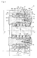
- Fig. 1 is a cross-sectional view of the entirety of a planetary reduction gear according to the example of the embodiment of the present invention
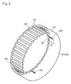
- Fig. 2 is a perspective view of an internal gear main body installed therein.
- a planetary reduction gear 10 is a so-called eccentric oscillation type planetary reduction gear that is widely used in robot joint driving or a driving system of a machine tool.
- the planetary reduction gear 10 has a casing 12 in which an external gear 14, an internal gear 16 with which the external gear 14 is internally meshed, and a pair of first and second carriers (carrier members) 21 and 22 which are respectively arranged on both axial sides of the external gear 14 are provided.
- the external gear 14 is internally meshed with the internal gear 16.
- the number of teeth of the external gear 14 is slightly (only by one in this example) smaller than the number of the teeth of the internal gear 16.
- the casing 12 and the internal gear 16 are configured to be separated from each other, and the internal gear 16 is disposed on the inner circumference of the casing 12. A configuration of a portion in the vicinity of the casing 12 and the internal gear 16 will be described below.
- Apin-shapedmember 32 penetrates respective external gears 14.
- a slide promoting member 33 is externally fitted to the pin-shaped member 32.
- the pair of first and second carriers 21 and 22 are respectively disposedonboth axial sides of the external gear 14, as described above.
- the first and second carriers 21 and 22 are connected with each other by means of the pin-shaped member 32, which is integrally formed with the second carrier 22, and a bolt 43.
- a driven member (not shown) is connected to the second carrier 22 by means of a tapped hole (not shown).
- the first and second carriers 21 and 22 are supported by the first main bearing (a main bearing on one side) 41, which is on a motor side, and the second main bearing (a main bearing on the other side) 42, which is on a load side.
- the first and second main bearings 41 and 42 are respectively disposed on both axial sides of the internal gear 16 and are constituted by angular contact ball bearings which are inserted in a back-to-back manner.
- the first main bearing 41 has a ball 41A as a rolling body, and a dedicated outer ring 41B
- the second main bearing 42 has a ball 42A as a rolling body, and a dedicated outer ring 42B.
- neither bearing has an inner ring (a part (an inner ring functioning portion) 21C or 22C of the outer circumference of the first or second carrier 21 or 22 also functions as an inner ring).
- the casing 12 and the internal gear 16 are configured to be separated from each other and the internal gear 16 is disposed on the inner circumference of the casing 12, as described above.
- the entirety of the casing 12 is formed in a substantially cylindrical shape.
- the entirety of the internal gear 16 is also formed in a substantially cylindrical shape. Meanwhile, an axial length Li of the internal gear 16 is shorter that an axial length Lc of the casing 12 (Li ⁇ Lc).
- the casing 12 is formed of an aluminum-based material with the intention of a decrease in weight and improvement in heat dissipation.
- the internal gear 16 is formed of a steel-based material which is subjected to heat treatment.
- the casing 12 and the internal gear 16 are formed of different materials.
- the casing 12 is formed of a material of which the heat dissipation is higher than the heat dissipation of the internal gear 16 and the specific gravity is smaller than the specific gravity of the internal gear 16.
- the internal gear 16 is formed of a material of which the hardness is greater than the hardness of the casing 12.
- the internal gear 16 is constituted to have an internal gear main body 16A and a pin member 16B which has a cylindrical shape and constitutes an internal tooth of the internal gear 16.
- a pin groove 16C which rotationally supports the pin member 16B is formed over the entire internal gear main body 16A in an axial direction.
- the cross-section of the pin groove 16C has a substantially semicircular shape.
- a retaining ring 50 abuts on a motor side end portion (one axial end) 16D (of the internal gear main body 16A) of the internal gear 16. Meanwhile, on the inner circumference of the motor side end portion of the casing 12, a retaining ring groove portion 12A with which the retaining ring 50 is engaged is formed in a ring shape over the entire circumference of the retaining ring groove portion 12A.
- the retaining ring groove portion 12A is formed at a position which is away from an axial end portion 12B by a distance as long as an axial length L3 of the outer ring 41B of the first main bearing 41.
- the retaining ring 50 is fitted to the retaining ring groove portion 12A on the casing 12, and thus the axial position of the retaining ring 50 is fixed on the casing 12. Furthermore, a projection length of the retaining ring 50 from the inner circumference of the casing 12 is set to H1 which is comparatively short. This ensures axial positioning rigidity of the retaining ring 50.
- the first main bearing 41 is pressed into the casing 12 until it comes into contact with a motor side end surface 50A of the retaining ring 50, and thus the first main bearing 41 is positioned at the casing 12 in the axial direction.
- the internal gear 16 is positioned at the casing 12 in the axial direction in such a manner that the motor side end portion 16D, which is one axial end (of the internal gear main body 16A) of the internal gear 16, abuts on a load side end surface 50B of the retaining ring 50.
- a load side end portion 16F which is the other axial end (of the internal gear main body 16A) of the internal gear 16, is positioned at the casing 12 by abutting on the outer ring 42B of the (press-fitted) second main bearing 42.
- first main bearing 41, the internal gear 16, and the second main bearing 42 are aligned in a state where these members are axially positioned on the inner circumference of the casing 12 by means of the retaining ring 50.
- first and second main bearings 41 and 42 are directly supported by the casing 12 without intervention of the internal gear 16.
- the first and second main bearings 41 and 42 are subjected to pressurization adjustment in such a manner that the first and second main bearings 41 and 42 are connected to each other with the bolt 43 via a shim 54 which is interposed between a bottom surface 21B of a recess 21A on the first carrier 21 and a tip end surface 32A of the pin-shaped member 32 of the second carrier 22.
- the ball 41A of the first main bearing 41, the outer ring 41B of the first main bearing 41, the retaining ring 50, the internal gear main body 16A, the outer ring 42B of the second main bearing 42, and the ball 42A of the second main bearing 42 are interposed between the inner ring functioning portions 21C and 22C of the first and second carriers 21 and 22 by a tightening force which is adjusted by means of the shim 54.
- these members are axially positioned at the casing 12, in a state where no gap is provided therebetween in terms of the axial position of the retaining ring 50.
- both ends 16B1 and 16B2 of each pin member 16B which constitutes the internal tooth of the internal gear 16 are axially positioned by the outer rings 41B and 42B of the first and second main bearings 41 and 42.
- the projection length H1 of the retaining ring 50 from the inner circumference of the casing 12 is set to be comparatively short is to prevent interference between the retaining ring 50 and the pin member 16B of the internal gear 16.
- the three external gears 14 are also axially positioned by the outer rings 41B and 42B of the first and second main bearings 41 and 42.
- the casing 12 and the internal gear 16 are subj ected to clearance fit and relative movement therebetween is regulated in a rotation direction (in a circumference direction).
- a key groove 16G enabling the engagement of the key 56 which regulates the relative movement in the rotation direction is formed on the outer circumference in the vicinity of the load side end portion 16F of the internal gear main body 16A of the internal gear 16.
- This key groove 16G is not formed over the entire internal gear 16 in the axial direction.
- the key groove 16G is formed only at a length L5 which is substantially as long as one-third of the entire internal gear 16 in the axial direction (which is about the same as the length of one of the three external gears 14).
- four key grooves 16G are formed in the circumference direction, as shown in Fig. 2 .
- four key grooves 12D are formed on the casing 12 in the circumference direction, so as to correspond to the key grooves 16G on the internal gear 16.
- the key grooves 16G on the internal gear 16 are disposed, in terms of the circumference direction, between the pin grooves 16C (in which the pinmembers 16B are disposed), as shown in Fig. 2 .
- a ring groove 12F on the casing 12 which is shown in Fig. 1 , functions as a tool clearance groove when forming the key groove 12D.
- the eccentric body 26 integrally formed on the input shaft 24 rotates.
- the external gear 14 oscillates via the roller 28.
- the number of teeth of the external gear 14 is smaller than the number of teeth of the internal gear 16 by only one. Therefore, for every rotation of the input shaft 24, the phase of the external gear 14 is shifted (rotates) by a degree of one tooth with respect to the internal gear 16.
- This rotation component is transmitted to the first and second carriers 21 and 22 via the slide promoting member 33 and the pin-shapedmember 32, and thus the drivenmember which is connected to the second carrier 22 via a tapped hole (not shown) is driven.
- the pair of first and second main bearings 41 and 42 are respectively disposed on both axial sides of the internal gear 16, in a state where the absolute position of the pair of the first and second main bearings with respect to the casing 12 is fixed by means of the retaining ring 50.
- the first and second main bearings 41 and 42 are supported by the casing 12 without intervention of the internal gear 16.
- the casing 12 except the internal gear
- the meshing load between the internal gear 16 and the external gear 14 is not directly applied to the radially outside parts of the first and second main bearings 41 and 42, and thus it is not necessary to ensure a thickness as great as that in the meshing portion. Therefore, it is possible to provide a compact planetary reduction gear 10 in which an outer diameter d1 of the casing 12 is reduced.
- the axial both ends 16B1 and 16B2 of the pin member 16B of the internal gear 16 are configured to be axially positioned by the outer rings 41B and 42B of the first and second main bearings 41 and 42, and thus it is not necessary to provide an additional member for positioning of the pin member 16B. Therefore, it is possible to further reduce the cost.
- the pin member when the internal gear (16) includes the pin member (16B), the pin member is not necessarily positioned by the outer rings (41B and 42B) of the main bearings (41 and 42).
- the retaining ring (50) is particularly disposed on the first main bearing (41) side in the casing (12), for example.
- it may be configured in a way that the radial projection length (H1) of the retaining ring (50) is slightly lengthened such that the pin member (16B) (in addition to the internal gear (16)) may be positioned by the retaining ring (50) itself.
- the positioning of the pinmember 16B to the motor side endportion 16B1 is performed, intentionally not by the retaining ring 50 but by the outer ring 41B of the first main bearing 41.
- the retaining ring 50 does not have a pin member 16B positioning function.
- the projection length H1 of the retaining ring 50 from the inner circumference of the casing 12 can be suppressed to be short. Therefore, it is possible to maintain the high axial rigidity of the retaining ring 50 itself and the high positional regulation rigidity of the retaining ring 50.
- the internal teeth of the internal gear are not necessarily formed by the pin members, and an internal gear in which internal teeth are directly formed on an internal gear main body in a gear-cutting manner may be applied. In this case, there is no need to press the internal teeth.
- the casing 12 and the internal gear 16 of the embodiment are subjected to the clearance fit and the relative movement therebetween is regulated, in a rotation direction, by the key 56.
- the cost is low and the installation is easy.
- the internal gear 16 is deformed by receiving a load from the external gear 14 side, and thus the internal gear 16 is also self-aligned.
- effects such as a gear-cutting error absorbing effect can be obtained.
- a formed length of the key 56 is not as long as the whole axial length Li of the internal gear 16 but is as long as the length L5. Furthermore, a plurality (four) of key grooves 16G are formed in the circumference direction and disposed between the pin grooves 16C in which the pin members 16B of the internal gear 16 are respectively disposed. In this configuration, it is possible to minimize stress concentration in the vicinity of the engaging portion between the key 56 and the internal gear main body 16A while adopting a "connection using a key". Thus, it is possible to maintain the high strength of the internal gear main body 16A.
- the casing 12 and the internal gear 16 are not necessarily connected in a clearance-fitting manner. Also, the casing 12 and the internal gear 16 are not necessarily connected using the key 56. In the present invention, the connection method such as a shrink fit is also not prohibited, for example. In this case, it is possible to cause internal stress, which is generated in the internal gear 16, to countervail the meshing load, which is generated between the internal gear 16 and the external gear 14, as in the case disclosed in Japanese Unexamined Patent Application Publication No. 2011-236988 (see Figs. 1 and 2 ). Thus, it is possible to achieve a more compact size.
- connection method such as a press fit or knurling can also be applied between the casing 12 and the internal gear 16, in addition to the method described above.
- a degree of freedom in configuration is high.
- the casing 12 and the internal gear 16 are connected in an interference fitting manner such as a shrink fit or a press fit, it is possible to provide a torque limiter function at the time of the application of excessive unexpected load or the like, by adjusting the extent of the interference fit such that the internal gear slides on the casing with an appropriate torque. Therefore, it is possible to effectively protect respective members constituting the power transmission system, without installing a dedicated torque limiter.
- the casing 12 of the embodiment is formed of the aluminum-based material and the internal gear 16 is formed of the steel-based material which is subj ected to heat treatment.
- the materials forming the casing 12 and the internal gear 16 are different from each other.
- the material forming the casing can be freely changed without significant restriction tomeet "a specificpurpose", because of a high degree of connection freedom.
- the casing 12 can be manufactured at low cost by using casting material.
- the embodiment particularly adopts the configuration in which "the casing 12 and the internal gear 16 are configured to be separated from each other, the internal gear 16 is disposed on the inner circumference of the casing 12, and the first and second main bearings 41 and 42 are supported by the casing 12 without intervention of the internal gear 16".
- the size of the internal gear 16 is relatively very small, compared to the size of the casing 12.
- the size of the casing 12 is quite large relative to the size of the internal gear 16. Therefore, if the weight reduction, the improvement in heat dissipation properties, or the like is intended as in this case, it is possible to very efficiently or significantly achieve the specific purpose.
- the planetary reduction gears 10 are used in series in such a manner that a plurality of reduction ratios are respectively allocated to the planetary reduction gears 10, corresponding to a plurality of large-small divisions (large-small divisions are defined conceptionally based on the transfer torque such as allowable torque, rated torque, or peak torque) defined by the magnitude of transmission torque.
- the casings 12 are (in terms of the same large-small divisions) commonly used regardless of the reduction ratios and the internal gear 16 of which the number of teeth (the number of the pin grooves 16C or the number of the pin members 16B) is set to be different in accordance with the reduction ratio is selectively internal-fitted to the casing 12.
- the casings 12 are (in terms of the same large-small divisions) commonly used regardless of the reduction ratios and the internal gear 16 of which the number of teeth (the number of the pin grooves 16C or the number of the pin members 16B) is set to be different in accordance with the reduction ratio is selectively internal-fitted to the casing 12.
- the manufacturing cost and the stocking cost can be significantly reduced.
- a so-called center crank type eccentric oscillation planetary reduction gear 10 in which only one input shaft 24 (an eccentric body shaft) provided with the eccentric body 26 is formed in the axis center O1 (a radial center) of the internal gear 16 is exemplified in the embodiment described above.
- a so-called distribution type eccentric oscillation planetary reduction gear that has a plurality of eccentric body shafts at the position offset from the axial center of an internal gear and causes an external gear to oscillate by rotating, in a synchronized manner, eccentric bodies formed on the plurality of eccentric body shafts also has been known.
- the present invention can also be applied to the distribution type eccentric oscillation planetary reduction gear in exactly the same way.
- the present invention can also be applied to the planetary reduction gear having a simple planetary gear speed reduction mechanism or the like.
Landscapes
- Engineering & Computer Science (AREA)
- General Engineering & Computer Science (AREA)
- Mechanical Engineering (AREA)
- Retarders (AREA)
- Mounting Of Bearings Or Others (AREA)
- Rolling Contact Bearings (AREA)
Applications Claiming Priority (1)
| Application Number | Priority Date | Filing Date | Title |
|---|---|---|---|
| JP2013041317A JP6137875B2 (ja) | 2013-03-01 | 2013-03-01 | 遊星歯車減速装置 |
Publications (3)
| Publication Number | Publication Date |
|---|---|
| EP2772664A2 true EP2772664A2 (de) | 2014-09-03 |
| EP2772664A3 EP2772664A3 (de) | 2015-12-16 |
| EP2772664B1 EP2772664B1 (de) | 2019-06-19 |
Family
ID=50101680
Family Applications (1)
| Application Number | Title | Priority Date | Filing Date |
|---|---|---|---|
| EP14020013.0A Active EP2772664B1 (de) | 2013-03-01 | 2014-02-11 | Planetengetriebe und eine Serie davon |
Country Status (3)
| Country | Link |
|---|---|
| EP (1) | EP2772664B1 (de) |
| JP (1) | JP6137875B2 (de) |
| CN (1) | CN104019189B (de) |
Cited By (3)
| Publication number | Priority date | Publication date | Assignee | Title |
|---|---|---|---|---|
| CN111043251A (zh) * | 2018-10-11 | 2020-04-21 | 住友重机械工业株式会社 | 偏心摆动型减速装置 |
| US11493112B2 (en) * | 2018-06-28 | 2022-11-08 | Sumitomo Heavy Industries, Ltd. | Speed reducer |
| CN118088630A (zh) * | 2024-04-26 | 2024-05-28 | 常州市曼多林精密机械科技股份有限公司 | 一种行星架自适型紧固的行星齿轮减速机 |
Families Citing this family (10)
| Publication number | Priority date | Publication date | Assignee | Title |
|---|---|---|---|---|
| US10167929B2 (en) * | 2016-06-22 | 2019-01-01 | Nidec-Shimpo (Zhe Jiang) Corporation | Speed reducer and actuator |
| JP6585648B2 (ja) * | 2017-03-15 | 2019-10-02 | 本田技研工業株式会社 | 軸受付構造体 |
| JP6863882B2 (ja) * | 2017-11-27 | 2021-04-21 | 住友重機械工業株式会社 | 遊星歯車装置及び遊星歯車装置の製造方法 |
| JP6898876B2 (ja) * | 2018-02-28 | 2021-07-07 | 住友重機械工業株式会社 | 偏心揺動型減速装置 |
| EP3708824B1 (de) * | 2019-03-12 | 2021-12-15 | Danfoss Power Solutions Inc. | Wiegenlageranordnung einer taumelscheibenartigen hydraulischen axialkolbeneinheit |
| DE102019121688B4 (de) * | 2019-08-12 | 2024-04-25 | Neugart Gmbh | Wellenlagerung, Getriebe sowie Verwendung eines Sicherungsrings |
| JP7262368B2 (ja) * | 2019-10-23 | 2023-04-21 | 住友重機械工業株式会社 | 歯車装置のシリーズ、その製造方法及び設計方法 |
| JP7474209B2 (ja) * | 2021-02-26 | 2024-04-24 | 美的集団股▲フン▼有限公司 | 内接噛合遊星歯車装置及びロボット用関節装置 |
| JP7764220B2 (ja) * | 2021-11-26 | 2025-11-05 | ナブテスコ株式会社 | 回転機構及びロボット |
| JP7764219B2 (ja) * | 2021-11-26 | 2025-11-05 | ナブテスコ株式会社 | 歯車機構及びロボット |
Citations (1)
| Publication number | Priority date | Publication date | Assignee | Title |
|---|---|---|---|---|
| JP2011236988A (ja) | 2010-05-11 | 2011-11-24 | Nabtesco Corp | 減速装置 |
Family Cites Families (12)
| Publication number | Priority date | Publication date | Assignee | Title |
|---|---|---|---|---|
| JP4201448B2 (ja) * | 1999-12-28 | 2008-12-24 | 住友重機械工業株式会社 | 内接噛合遊星歯車構造を採用した変速機のシリーズ |
| JP4847892B2 (ja) * | 2007-02-22 | 2011-12-28 | 住友重機械工業株式会社 | 揺動内接噛合遊星歯車装置及びその偏心体軸の製造方法 |
| DE102007023951A1 (de) * | 2007-05-23 | 2008-12-04 | Zf Friedrichshafen Ag | Lagerung eines Stirnrades in einem Getriebe |
| JP4688909B2 (ja) * | 2008-07-24 | 2011-05-25 | 住友重機械工業株式会社 | 内接噛合遊星歯車構造を採用した変速機のシリーズ |
| JP2010169247A (ja) * | 2008-12-26 | 2010-08-05 | Ntn Corp | 鉄道車両駆動ユニット |
| JP5270462B2 (ja) * | 2009-06-15 | 2013-08-21 | ナブテスコ株式会社 | 偏心揺動型歯車装置および偏心揺動型歯車装置におけるクランク軸の組み付け方法 |
| EP2513636B1 (de) * | 2009-12-18 | 2020-08-05 | Koninklijke Philips N.V. | Apparat zur bestimmung einer substanz |
| CN101725673B (zh) * | 2010-02-01 | 2011-12-07 | 重庆大学 | 滤波减速器 |
| JP5400648B2 (ja) * | 2010-02-08 | 2014-01-29 | ナブテスコ株式会社 | 歯車伝動装置 |
| JP5603717B2 (ja) * | 2010-09-06 | 2014-10-08 | 住友重機械工業株式会社 | 揺動内接噛合型の遊星歯車装置およびその製造方法 |
| JP5490752B2 (ja) * | 2011-06-24 | 2014-05-14 | 住友重機械工業株式会社 | 揺動内接噛合型の減速装置 |
| JP5822392B2 (ja) * | 2011-12-15 | 2015-11-24 | 住友重機械工業株式会社 | 偏心揺動型減速機 |
-
2013
- 2013-03-01 JP JP2013041317A patent/JP6137875B2/ja active Active
-
2014
- 2014-01-02 CN CN201410004303.0A patent/CN104019189B/zh active Active
- 2014-02-11 EP EP14020013.0A patent/EP2772664B1/de active Active
Patent Citations (1)
| Publication number | Priority date | Publication date | Assignee | Title |
|---|---|---|---|---|
| JP2011236988A (ja) | 2010-05-11 | 2011-11-24 | Nabtesco Corp | 減速装置 |
Cited By (3)
| Publication number | Priority date | Publication date | Assignee | Title |
|---|---|---|---|---|
| US11493112B2 (en) * | 2018-06-28 | 2022-11-08 | Sumitomo Heavy Industries, Ltd. | Speed reducer |
| CN111043251A (zh) * | 2018-10-11 | 2020-04-21 | 住友重机械工业株式会社 | 偏心摆动型减速装置 |
| CN118088630A (zh) * | 2024-04-26 | 2024-05-28 | 常州市曼多林精密机械科技股份有限公司 | 一种行星架自适型紧固的行星齿轮减速机 |
Also Published As
| Publication number | Publication date |
|---|---|
| CN104019189A (zh) | 2014-09-03 |
| EP2772664B1 (de) | 2019-06-19 |
| JP6137875B2 (ja) | 2017-05-31 |
| JP2014169736A (ja) | 2014-09-18 |
| EP2772664A3 (de) | 2015-12-16 |
| CN104019189B (zh) | 2016-08-17 |
Similar Documents
| Publication | Publication Date | Title |
|---|---|---|
| EP2772664B1 (de) | Planetengetriebe und eine Serie davon | |
| US11808338B2 (en) | Harmonic pin ring gearing | |
| EP2180210A1 (de) | Untersetzungsgetriebe | |
| JP6031397B2 (ja) | 撓み噛合い式歯車装置 | |
| WO2012128003A1 (ja) | サイクロイド減速機及びインホイールモータ駆動装置 | |
| US20190011039A1 (en) | Planetary gear mechanism | |
| JP2014224548A (ja) | カム装置 | |
| US9644677B2 (en) | Preliminary retainer for radial needle bearing | |
| KR101403538B1 (ko) | 편심요동형의 감속기 | |
| US10495183B2 (en) | Gear device | |
| JP5552359B2 (ja) | 減速装置 | |
| EP2848832B1 (de) | Wellenunterstützungsstruktur und Verfahren zur Herstellung der Wellenunterstützungsvorrichtung | |
| US20160061291A1 (en) | Eccentric oscillation gear device and torque adjusting method therefor | |
| EP3270002A1 (de) | Getriebevorrichtung | |
| JP2017180799A (ja) | 波動歯車減速機 | |
| EP2730805B1 (de) | Untersetzungsgetriebe | |
| JP5961520B2 (ja) | 偏心揺動型の減速装置 | |
| US10814543B2 (en) | Transmission gear system of multi-screw extruder or kneader | |
| CN111480022B (zh) | 啮合设施 | |
| KR102262294B1 (ko) | 기어 전동 장치 | |
| EP2657569A1 (de) | Getriebevorrichtung | |
| JP7226674B1 (ja) | ボールねじ装置 | |
| JP2005344885A (ja) | 遊星ローラ型減速機及び減速機シリーズ | |
| JP2024058020A (ja) | ボールねじ装置 |
Legal Events
| Date | Code | Title | Description |
|---|---|---|---|
| PUAI | Public reference made under article 153(3) epc to a published international application that has entered the european phase |
Free format text: ORIGINAL CODE: 0009012 |
|
| 17P | Request for examination filed |
Effective date: 20140211 |
|
| AK | Designated contracting states |
Kind code of ref document: A2 Designated state(s): AL AT BE BG CH CY CZ DE DK EE ES FI FR GB GR HR HU IE IS IT LI LT LU LV MC MK MT NL NO PL PT RO RS SE SI SK SM TR |
|
| AX | Request for extension of the european patent |
Extension state: BA ME |
|
| RIC1 | Information provided on ipc code assigned before grant |
Ipc: F16H 1/32 20060101AFI20150722BHEP |
|
| PUAL | Search report despatched |
Free format text: ORIGINAL CODE: 0009013 |
|
| AK | Designated contracting states |
Kind code of ref document: A3 Designated state(s): AL AT BE BG CH CY CZ DE DK EE ES FI FR GB GR HR HU IE IS IT LI LT LU LV MC MK MT NL NO PL PT RO RS SE SI SK SM TR |
|
| AX | Request for extension of the european patent |
Extension state: BA ME |
|
| RIC1 | Information provided on ipc code assigned before grant |
Ipc: F16H 1/32 20060101AFI20151109BHEP |
|
| R17P | Request for examination filed (corrected) |
Effective date: 20160616 |
|
| RBV | Designated contracting states (corrected) |
Designated state(s): AL AT BE BG CH CY CZ DE DK EE ES FI FR GB GR HR HU IE IS IT LI LT LU LV MC MK MT NL NO PL PT RO RS SE SI SK SM TR |
|
| REG | Reference to a national code |
Ref country code: DE Ref legal event code: R079 Ref document number: 602014048485 Country of ref document: DE Free format text: PREVIOUS MAIN CLASS: F16H0001320000 Ipc: F16H0057080000 |
|
| RIC1 | Information provided on ipc code assigned before grant |
Ipc: F16H 57/08 20060101AFI20181129BHEP Ipc: F16H 1/32 20060101ALI20181129BHEP |
|
| GRAP | Despatch of communication of intention to grant a patent |
Free format text: ORIGINAL CODE: EPIDOSNIGR1 |
|
| STAA | Information on the status of an ep patent application or granted ep patent |
Free format text: STATUS: GRANT OF PATENT IS INTENDED |
|
| INTG | Intention to grant announced |
Effective date: 20190109 |
|
| GRAS | Grant fee paid |
Free format text: ORIGINAL CODE: EPIDOSNIGR3 |
|
| GRAA | (expected) grant |
Free format text: ORIGINAL CODE: 0009210 |
|
| STAA | Information on the status of an ep patent application or granted ep patent |
Free format text: STATUS: THE PATENT HAS BEEN GRANTED |
|
| AK | Designated contracting states |
Kind code of ref document: B1 Designated state(s): AL AT BE BG CH CY CZ DE DK EE ES FI FR GB GR HR HU IE IS IT LI LT LU LV MC MK MT NL NO PL PT RO RS SE SI SK SM TR |
|
| REG | Reference to a national code |
Ref country code: GB Ref legal event code: FG4D |
|
| REG | Reference to a national code |
Ref country code: CH Ref legal event code: EP |
|
| REG | Reference to a national code |
Ref country code: IE Ref legal event code: FG4D |
|
| REG | Reference to a national code |
Ref country code: DE Ref legal event code: R096 Ref document number: 602014048485 Country of ref document: DE |
|
| REG | Reference to a national code |
Ref country code: AT Ref legal event code: REF Ref document number: 1145942 Country of ref document: AT Kind code of ref document: T Effective date: 20190715 |
|
| REG | Reference to a national code |
Ref country code: NL Ref legal event code: MP Effective date: 20190619 |
|
| PG25 | Lapsed in a contracting state [announced via postgrant information from national office to epo] |
Ref country code: LT Free format text: LAPSE BECAUSE OF FAILURE TO SUBMIT A TRANSLATION OF THE DESCRIPTION OR TO PAY THE FEE WITHIN THE PRESCRIBED TIME-LIMIT Effective date: 20190619 Ref country code: HR Free format text: LAPSE BECAUSE OF FAILURE TO SUBMIT A TRANSLATION OF THE DESCRIPTION OR TO PAY THE FEE WITHIN THE PRESCRIBED TIME-LIMIT Effective date: 20190619 Ref country code: FI Free format text: LAPSE BECAUSE OF FAILURE TO SUBMIT A TRANSLATION OF THE DESCRIPTION OR TO PAY THE FEE WITHIN THE PRESCRIBED TIME-LIMIT Effective date: 20190619 Ref country code: AL Free format text: LAPSE BECAUSE OF FAILURE TO SUBMIT A TRANSLATION OF THE DESCRIPTION OR TO PAY THE FEE WITHIN THE PRESCRIBED TIME-LIMIT Effective date: 20190619 Ref country code: NO Free format text: LAPSE BECAUSE OF FAILURE TO SUBMIT A TRANSLATION OF THE DESCRIPTION OR TO PAY THE FEE WITHIN THE PRESCRIBED TIME-LIMIT Effective date: 20190919 Ref country code: SE Free format text: LAPSE BECAUSE OF FAILURE TO SUBMIT A TRANSLATION OF THE DESCRIPTION OR TO PAY THE FEE WITHIN THE PRESCRIBED TIME-LIMIT Effective date: 20190619 |
|
| REG | Reference to a national code |
Ref country code: LT Ref legal event code: MG4D |
|
| PG25 | Lapsed in a contracting state [announced via postgrant information from national office to epo] |
Ref country code: GR Free format text: LAPSE BECAUSE OF FAILURE TO SUBMIT A TRANSLATION OF THE DESCRIPTION OR TO PAY THE FEE WITHIN THE PRESCRIBED TIME-LIMIT Effective date: 20190920 Ref country code: RS Free format text: LAPSE BECAUSE OF FAILURE TO SUBMIT A TRANSLATION OF THE DESCRIPTION OR TO PAY THE FEE WITHIN THE PRESCRIBED TIME-LIMIT Effective date: 20190619 Ref country code: BG Free format text: LAPSE BECAUSE OF FAILURE TO SUBMIT A TRANSLATION OF THE DESCRIPTION OR TO PAY THE FEE WITHIN THE PRESCRIBED TIME-LIMIT Effective date: 20190919 Ref country code: LV Free format text: LAPSE BECAUSE OF FAILURE TO SUBMIT A TRANSLATION OF THE DESCRIPTION OR TO PAY THE FEE WITHIN THE PRESCRIBED TIME-LIMIT Effective date: 20190619 |
|
| REG | Reference to a national code |
Ref country code: AT Ref legal event code: MK05 Ref document number: 1145942 Country of ref document: AT Kind code of ref document: T Effective date: 20190619 |
|
| PG25 | Lapsed in a contracting state [announced via postgrant information from national office to epo] |
Ref country code: PT Free format text: LAPSE BECAUSE OF FAILURE TO SUBMIT A TRANSLATION OF THE DESCRIPTION OR TO PAY THE FEE WITHIN THE PRESCRIBED TIME-LIMIT Effective date: 20191021 Ref country code: EE Free format text: LAPSE BECAUSE OF FAILURE TO SUBMIT A TRANSLATION OF THE DESCRIPTION OR TO PAY THE FEE WITHIN THE PRESCRIBED TIME-LIMIT Effective date: 20190619 Ref country code: SK Free format text: LAPSE BECAUSE OF FAILURE TO SUBMIT A TRANSLATION OF THE DESCRIPTION OR TO PAY THE FEE WITHIN THE PRESCRIBED TIME-LIMIT Effective date: 20190619 Ref country code: AT Free format text: LAPSE BECAUSE OF FAILURE TO SUBMIT A TRANSLATION OF THE DESCRIPTION OR TO PAY THE FEE WITHIN THE PRESCRIBED TIME-LIMIT Effective date: 20190619 Ref country code: RO Free format text: LAPSE BECAUSE OF FAILURE TO SUBMIT A TRANSLATION OF THE DESCRIPTION OR TO PAY THE FEE WITHIN THE PRESCRIBED TIME-LIMIT Effective date: 20190619 Ref country code: CZ Free format text: LAPSE BECAUSE OF FAILURE TO SUBMIT A TRANSLATION OF THE DESCRIPTION OR TO PAY THE FEE WITHIN THE PRESCRIBED TIME-LIMIT Effective date: 20190619 Ref country code: NL Free format text: LAPSE BECAUSE OF FAILURE TO SUBMIT A TRANSLATION OF THE DESCRIPTION OR TO PAY THE FEE WITHIN THE PRESCRIBED TIME-LIMIT Effective date: 20190619 |
|
| PG25 | Lapsed in a contracting state [announced via postgrant information from national office to epo] |
Ref country code: SM Free format text: LAPSE BECAUSE OF FAILURE TO SUBMIT A TRANSLATION OF THE DESCRIPTION OR TO PAY THE FEE WITHIN THE PRESCRIBED TIME-LIMIT Effective date: 20190619 Ref country code: IS Free format text: LAPSE BECAUSE OF FAILURE TO SUBMIT A TRANSLATION OF THE DESCRIPTION OR TO PAY THE FEE WITHIN THE PRESCRIBED TIME-LIMIT Effective date: 20191019 Ref country code: ES Free format text: LAPSE BECAUSE OF FAILURE TO SUBMIT A TRANSLATION OF THE DESCRIPTION OR TO PAY THE FEE WITHIN THE PRESCRIBED TIME-LIMIT Effective date: 20190619 Ref country code: IT Free format text: LAPSE BECAUSE OF FAILURE TO SUBMIT A TRANSLATION OF THE DESCRIPTION OR TO PAY THE FEE WITHIN THE PRESCRIBED TIME-LIMIT Effective date: 20190619 |
|
| PG25 | Lapsed in a contracting state [announced via postgrant information from national office to epo] |
Ref country code: TR Free format text: LAPSE BECAUSE OF FAILURE TO SUBMIT A TRANSLATION OF THE DESCRIPTION OR TO PAY THE FEE WITHIN THE PRESCRIBED TIME-LIMIT Effective date: 20190619 |
|
| PG25 | Lapsed in a contracting state [announced via postgrant information from national office to epo] |
Ref country code: PL Free format text: LAPSE BECAUSE OF FAILURE TO SUBMIT A TRANSLATION OF THE DESCRIPTION OR TO PAY THE FEE WITHIN THE PRESCRIBED TIME-LIMIT Effective date: 20190619 Ref country code: DK Free format text: LAPSE BECAUSE OF FAILURE TO SUBMIT A TRANSLATION OF THE DESCRIPTION OR TO PAY THE FEE WITHIN THE PRESCRIBED TIME-LIMIT Effective date: 20190619 |
|
| PG25 | Lapsed in a contracting state [announced via postgrant information from national office to epo] |
Ref country code: IS Free format text: LAPSE BECAUSE OF FAILURE TO SUBMIT A TRANSLATION OF THE DESCRIPTION OR TO PAY THE FEE WITHIN THE PRESCRIBED TIME-LIMIT Effective date: 20200224 |
|
| REG | Reference to a national code |
Ref country code: DE Ref legal event code: R097 Ref document number: 602014048485 Country of ref document: DE |
|
| PLBE | No opposition filed within time limit |
Free format text: ORIGINAL CODE: 0009261 |
|
| STAA | Information on the status of an ep patent application or granted ep patent |
Free format text: STATUS: NO OPPOSITION FILED WITHIN TIME LIMIT |
|
| PG2D | Information on lapse in contracting state deleted |
Ref country code: IS |
|
| 26N | No opposition filed |
Effective date: 20200603 |
|
| PG25 | Lapsed in a contracting state [announced via postgrant information from national office to epo] |
Ref country code: SI Free format text: LAPSE BECAUSE OF FAILURE TO SUBMIT A TRANSLATION OF THE DESCRIPTION OR TO PAY THE FEE WITHIN THE PRESCRIBED TIME-LIMIT Effective date: 20190619 |
|
| REG | Reference to a national code |
Ref country code: CH Ref legal event code: PL |
|
| GBPC | Gb: european patent ceased through non-payment of renewal fee |
Effective date: 20200211 |
|
| REG | Reference to a national code |
Ref country code: BE Ref legal event code: MM Effective date: 20200229 |
|
| PG25 | Lapsed in a contracting state [announced via postgrant information from national office to epo] |
Ref country code: LU Free format text: LAPSE BECAUSE OF NON-PAYMENT OF DUE FEES Effective date: 20200211 Ref country code: MC Free format text: LAPSE BECAUSE OF FAILURE TO SUBMIT A TRANSLATION OF THE DESCRIPTION OR TO PAY THE FEE WITHIN THE PRESCRIBED TIME-LIMIT Effective date: 20190619 |
|
| PG25 | Lapsed in a contracting state [announced via postgrant information from national office to epo] |
Ref country code: LI Free format text: LAPSE BECAUSE OF NON-PAYMENT OF DUE FEES Effective date: 20200229 Ref country code: CH Free format text: LAPSE BECAUSE OF NON-PAYMENT OF DUE FEES Effective date: 20200229 |
|
| PG25 | Lapsed in a contracting state [announced via postgrant information from national office to epo] |
Ref country code: IE Free format text: LAPSE BECAUSE OF NON-PAYMENT OF DUE FEES Effective date: 20200211 Ref country code: GB Free format text: LAPSE BECAUSE OF NON-PAYMENT OF DUE FEES Effective date: 20200211 Ref country code: FR Free format text: LAPSE BECAUSE OF NON-PAYMENT OF DUE FEES Effective date: 20200229 |
|
| PG25 | Lapsed in a contracting state [announced via postgrant information from national office to epo] |
Ref country code: BE Free format text: LAPSE BECAUSE OF NON-PAYMENT OF DUE FEES Effective date: 20200229 |
|
| PG25 | Lapsed in a contracting state [announced via postgrant information from national office to epo] |
Ref country code: MT Free format text: LAPSE BECAUSE OF FAILURE TO SUBMIT A TRANSLATION OF THE DESCRIPTION OR TO PAY THE FEE WITHIN THE PRESCRIBED TIME-LIMIT Effective date: 20190619 Ref country code: CY Free format text: LAPSE BECAUSE OF FAILURE TO SUBMIT A TRANSLATION OF THE DESCRIPTION OR TO PAY THE FEE WITHIN THE PRESCRIBED TIME-LIMIT Effective date: 20190619 |
|
| PG25 | Lapsed in a contracting state [announced via postgrant information from national office to epo] |
Ref country code: MK Free format text: LAPSE BECAUSE OF FAILURE TO SUBMIT A TRANSLATION OF THE DESCRIPTION OR TO PAY THE FEE WITHIN THE PRESCRIBED TIME-LIMIT Effective date: 20190619 |
|
| PGFP | Annual fee paid to national office [announced via postgrant information from national office to epo] |
Ref country code: DE Payment date: 20251230 Year of fee payment: 13 |