EP2772691A1 - Appareil de cuisson par chauffage - Google Patents
Appareil de cuisson par chauffage Download PDFInfo
- Publication number
- EP2772691A1 EP2772691A1 EP12843207.7A EP12843207A EP2772691A1 EP 2772691 A1 EP2772691 A1 EP 2772691A1 EP 12843207 A EP12843207 A EP 12843207A EP 2772691 A1 EP2772691 A1 EP 2772691A1
- Authority
- EP
- European Patent Office
- Prior art keywords
- casing
- built
- storage unit
- air
- turntable
- Prior art date
- Legal status (The legal status is an assumption and is not a legal conclusion. Google has not performed a legal analysis and makes no representation as to the accuracy of the status listed.)
- Withdrawn
Links
- 238000010438 heat treatment Methods 0.000 title claims abstract description 74
- 238000001816 cooling Methods 0.000 claims abstract description 51
- 230000020169 heat generation Effects 0.000 description 4
- 239000002184 metal Substances 0.000 description 2
- 230000000694 effects Effects 0.000 description 1
- 238000012986 modification Methods 0.000 description 1
- 230000004048 modification Effects 0.000 description 1
- 238000012856 packing Methods 0.000 description 1
- 230000001105 regulatory effect Effects 0.000 description 1
- 239000011347 resin Substances 0.000 description 1
- 229920005989 resin Polymers 0.000 description 1
Images


Classifications
-
- F—MECHANICAL ENGINEERING; LIGHTING; HEATING; WEAPONS; BLASTING
- F24—HEATING; RANGES; VENTILATING
- F24C—DOMESTIC STOVES OR RANGES ; DETAILS OF DOMESTIC STOVES OR RANGES, OF GENERAL APPLICATION
- F24C7/00—Stoves or ranges heated by electric energy
- F24C7/02—Stoves or ranges heated by electric energy using microwaves
-
- F—MECHANICAL ENGINEERING; LIGHTING; HEATING; WEAPONS; BLASTING
- F24—HEATING; RANGES; VENTILATING
- F24C—DOMESTIC STOVES OR RANGES ; DETAILS OF DOMESTIC STOVES OR RANGES, OF GENERAL APPLICATION
- F24C15/00—Details
- F24C15/006—Arrangements for circulation of cooling air
-
- H—ELECTRICITY
- H05—ELECTRIC TECHNIQUES NOT OTHERWISE PROVIDED FOR
- H05B—ELECTRIC HEATING; ELECTRIC LIGHT SOURCES NOT OTHERWISE PROVIDED FOR; CIRCUIT ARRANGEMENTS FOR ELECTRIC LIGHT SOURCES, IN GENERAL
- H05B6/00—Heating by electric, magnetic or electromagnetic fields
- H05B6/64—Heating using microwaves
- H05B6/6408—Supports or covers specially adapted for use in microwave heating apparatus
- H05B6/6411—Supports or covers specially adapted for use in microwave heating apparatus the supports being rotated
-
- H—ELECTRICITY
- H05—ELECTRIC TECHNIQUES NOT OTHERWISE PROVIDED FOR
- H05B—ELECTRIC HEATING; ELECTRIC LIGHT SOURCES NOT OTHERWISE PROVIDED FOR; CIRCUIT ARRANGEMENTS FOR ELECTRIC LIGHT SOURCES, IN GENERAL
- H05B6/00—Heating by electric, magnetic or electromagnetic fields
- H05B6/64—Heating using microwaves
- H05B6/642—Cooling of the microwave components and related air circulation systems
-
- H—ELECTRICITY
- H05—ELECTRIC TECHNIQUES NOT OTHERWISE PROVIDED FOR
- H05B—ELECTRIC HEATING; ELECTRIC LIGHT SOURCES NOT OTHERWISE PROVIDED FOR; CIRCUIT ARRANGEMENTS FOR ELECTRIC LIGHT SOURCES, IN GENERAL
- H05B6/00—Heating by electric, magnetic or electromagnetic fields
- H05B6/64—Heating using microwaves
- H05B6/6426—Aspects relating to the exterior of the microwave heating apparatus, e.g. metal casing, power cord
- H05B6/6429—Aspects relating to mounting assemblies of wall-mounted microwave ovens
Definitions
- the present invention relates to a heating cooker and more particularly, to a heating cooker having a turntable within a heating chamber.
- a conventional heating cooker has a heating chamber within a casing, and a turntable placed at a bottom of the heating chamber (see, for example, JP 2001-41462 (PTL1)).
- the turntable which is placed within the heating chamber, is driven to rotate by a turntable motor which is placed within the casing and below the heating chamber.
- the heating cooker has the following problems. That is, temperatures around the turntable motor, which is placed between the bottom of the heating chamber and the bottom of the casing, are raised by heat coming from the heating chamber. Therefore, countermeasures against heat such as use of a heat resistant motor, use of additional ducts for cooling the motor, and/or the like have to be taken. This increases costs.
- the present invention aims at providing a heating cooker which is able to effectively cool a turntable motor by a simple structure and hence at a low cost.
- a heating cooker according to an aspect of the present invention includes:
- the built-in storage unit may be a recess provided below a top plate of a so-called system kitchen and having a front opening (i.e., an opening on a front side of the system kitchen) or a box type storage unit having an opening on its front side.
- the heating cooker of this embodiment allows for use of a less expensive versatile motor, without requiring use of a high temperature resistant motor or use of additional cooling ducts. Therefore, the present invention allows for effective cooling of the turntable motor without use of a high temperature resistant motor or use of additional cooling ducts, but with a simple structure and hence at a low cost.
- the cooling fan is placed on a back side of the casing and, in the state that the casing is mounted within the built-in storage unit, supplies the air, taken in from the front side of the casing, through the space between the lower face of the casing and the bottom face of the built-in storage unit and then a space between a back face of the casing and a back face of the built-in storage unit into the casing.
- the cooling fan is used both for cooling the turntable motor and for cooling such heat generation parts in the casing.
- the heating cooker further includes a guide cover provided at a bottom of the casing so as to cover the turntable motor, and configured to guide the air, taken in from the front side of the casing, toward the back face of the casing.
- the guide cover which is provided at the bottom of the casing so as to cover the turntable motor, protects the turntable motor and also smoothly guides or directs some of air, taken in from the front side of the casing by the cooling fan, toward the back face of the casing after the air has been used to cool the turntable motor.
- air supplied into the casing by the cooling fan passes through the casing and is discharged forward through an exhaust port provided at the front side of the casing.
- air supplied into the casing by the cooling fan passes through the casing and is discharged forward through the exhaust port provided at the front side of the casing.
- an air passage is established from take-in to discharge of the air by the cooling air to thereby provide a smooth air flow.
- a cooling efficiency is improved.
- the heating cooker of the present invention will be described below by way of an embodiment shown in the attached figures.
- Fig. 1 shows a front view of a heating cooker according to an embodiment of the present invention.
- This heating cooker has, as shown in Fig. 1 , a metal casing 1 of a rectangular parallelepiped shape, a heating chamber 2 provided within the casing 1 and having an opening 2a, and a door 6 pivotable, or swingable, about near a lower edge of a front panel 10 of the casing 1.
- the casing 1 is provided with four legs 7 at its bottom and a guide cover 25 at a central part of the bottom.
- the guide cover 25 has a plurality of slits on its front side, as well as on its back side although not shown in the figure.
- the front panel 10 has, above the opening 2a of the heating chamber 2, a display and operation section 11 including a display part and operation buttons.
- the front panel 10 also has an exhaust port 12 between the opening 2a of the heating chamber and the display and operation section 11.
- the exhaust port 12 includes a plurality of slits arranged transversely in one line.
- the exhaust port 12 is arranged and configured such that it is not closed by the door 6 when the door 6 is closed.
- a turntable 20 is provided at the bottom of the heating chamber 2, with the turntable 20 rotatably supported.
- the heating cooker is mounted within a built-in storage unit 100 having a front opening 100a.
- Fig. 2 shows a left side view of the heating cooker.
- the heating cooker is shown with a top plate and a side plate of the casing 1 removed and with the door 6 being fully open.
- reference numeral 23 indicates a turntable motor.
- a cooling fan 3 is placed on a back side of the casing 1.
- the cooling fan 3 functions to take in air from the front side of the casing 1 and circulates the air through a space between a lower face of the casing 1 and a bottom face of the built-in storage unit 100 and then a space between a back face of the casing 1 and a back face of the built-in storage unit 100 into the casing 1, as indicated by arrows R1 and R2.
- the heating cooker also has a holder 4 made of metal or resin and a board 5 supported by the holder 4.
- the holder 4 is placed on an upper left side of the heating chamber 2 as viewed from the door 6 side.
- the board 5 is mounted with things such as a lamp for illuminating the inside of the heating chamber.
- the door 6 has a handle 8 for opening and closing the door 6 at an upper part thereof.
- a lower part of the door 6 is connected with a front part of a bottom plate 1a of the casing 1 through a cam mechanism 9 such that when closing the door 6, a spring member (not shown) constituting a part of the cam mechanism 9 urges the door 6 to its closed position.
- Fig. 3 shows a top view of the heating cooker.
- the heating cooker is shown with the top plate and the side plates of the casing 1 removed and with the door 6 fully closed.
- the magnetron 13, the high voltage transformer 14 and the control unit 15 are arranged in a space between a top face of the casing 1 and a top face of the heating chamber 2 such that air blown from the cooling fan 3 cools the magnetron 13, the high voltage transformer 14 and the control unit 15.
- Microwave produced by the magnetron 13 is guided by a waveguide 18 to an upper central part of the heating chamber 2, at which part the microwave is stirred by an antenna (not shown) and radiated toward a lower part of the heating chamber 2 to thereby heat an object to be cooked.
- the cooling fan 3 is driven by a cooling fan motor 16 placed within the casing 1 on the back side of the heating cooker.
- a plurality of air regulating plates are provided between the cooling fan 3 and the devices such as the magnetron 13, high voltage transformer 14 and control unit 15 such that air blown from the cooling fan 3 is uniformly applied to these devices.
- the air blown from the cooling fan 3 is eventually discharged through the exhaust port 12 (shown in Fig. 1 ) provided at the front panel 10.
- Fig. 4 shows a vertical cross sectional view of an essential lower part of the heating cooker.
- the turntable 20 placed at the bottom of the heating chamber 2 is rotatably supported by a roller stay 21.
- the roller stay 21 has a plurality of extending parts 21b that extend from a central part 21a radially outward such that extremities of the extending parts are circumferentially spaced at equal intervals from each other.
- the roller stay 21 also has a plurality of rollers 22 attached to the extremities of the extending parts 21b.
- An end of a driving shaft 23a of the turntable motor 23 placed below the heating chamber 2 is fixed to the central part 21a of the roller stay 21.
- the driving shaft 23a of the turntable motor 23 passes through a bottom plate 2b of the heating chamber 2.
- the turntable motor 23 is fixed to the bottom plate 2b of the heating chamber 2 through a motor mount plate 24.
- the bottom plate 1a of the casing 1 is recessed upward to define a recess 30, and the recess 30 has a hole 30a at a center thereof.
- the turntable motor 23 and a part of the motor mount plate 24 extend downwards through the central hole 30a of the recess 30. In this way, the turntable motor 23 is arranged below the heating chamber 2 and also below the casing 1.
- a heat resistant rubber packing 31 is provided between an edge of the hole 30a at the bottom plate 1a of the casing 1 and the bottom plate 2b of the heating chamber 2.
- the guide cover 25 is mounted to the bottom plate 1a of the casing 1 in such a manner that the guide cover 25 covers the recess 30 at the bottom plate 1a of the casing 1 and the turntable motor 23.
- the guide cover 25, in this embodiment, has a box shape having an upper opening. But, such a shape is not limitative and the guide cover 25 may have any other shape as far as the shape allows the guide cover 25 to protect the turntable motor as well as to smoothly guide or direct some of air, taken in from the front side of the casing by the cooling fan, toward the back face of the casing after the air has been used to cool the turntable motor.
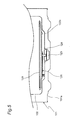
- a turntable motor 123 is placed within a casing 101 and between a bottom plate 102b of a heating chamber 102 and a bottom plate 101a of the casing 101. Therefore, it is necessary to take countermeasures against heat such as use of a high temperature resistant motor for the turntable motor 123 and/or use of an additional duct for cooling the turntable motor 123.
- reference numeral 120 indicates a turntable
- 121 indicates a roller stay
- 124 indicates a motor mount plate.
- the heating cooker of this embodiment allows for use of a less expensive versatile motor, without requiring use of a high temperature resistant motor or use of additional cooling ducts. Also, the heating cooker of this embodiment allows for the effective cooling of the turntable motor 23 to provide improved reliability of the turntable motor 23 with use of a simple structure and hence at a low cost.
- the guide cover 25 attached to the bottom of the casing 1 so as to cover the turntable motor 23 serves to protect the turntable motor 23.
- the guide cover 25 serves to smoothly guide toward the back face of the casing a part of air taken in from the front side of the casing 1 by the cooling fan 3 after the part of air is used to cool the turntable motor 23.
- Air supplied into the casing 1 by the cooling fan 3 passes through the casing 1 and is discharged forward through the exhaust port 12 provided at the front side of the casing 1.
- Air supplied into the casing 1 by the cooling fan 3 passes through the casing 1 and is discharged forward through the exhaust port 12 provided at the front side of the casing 1.
- the above embodiment has described the heating cooker housed in the built-in storage unit 100.
- the present invention is, however, applicable to a heating cooker which is to be housed in a dedicated storage box serving as a built-in storage unit.
Landscapes
- Engineering & Computer Science (AREA)
- Physics & Mathematics (AREA)
- Electromagnetism (AREA)
- Chemical & Material Sciences (AREA)
- Combustion & Propulsion (AREA)
- Mechanical Engineering (AREA)
- General Engineering & Computer Science (AREA)
- Electric Ovens (AREA)
Applications Claiming Priority (2)
| Application Number | Priority Date | Filing Date | Title |
|---|---|---|---|
| JP2011237504A JP2013096598A (ja) | 2011-10-28 | 2011-10-28 | 加熱調理器 |
| PCT/JP2012/077467 WO2013062001A1 (fr) | 2011-10-28 | 2012-10-24 | Appareil de cuisson par chauffage |
Publications (2)
| Publication Number | Publication Date |
|---|---|
| EP2772691A1 true EP2772691A1 (fr) | 2014-09-03 |
| EP2772691A4 EP2772691A4 (fr) | 2015-07-15 |
Family
ID=48167828
Family Applications (1)
| Application Number | Title | Priority Date | Filing Date |
|---|---|---|---|
| EP12843207.7A Withdrawn EP2772691A4 (fr) | 2011-10-28 | 2012-10-24 | Appareil de cuisson par chauffage |
Country Status (4)
| Country | Link |
|---|---|
| US (1) | US10161637B2 (fr) |
| EP (1) | EP2772691A4 (fr) |
| JP (1) | JP2013096598A (fr) |
| WO (1) | WO2013062001A1 (fr) |
Cited By (1)
| Publication number | Priority date | Publication date | Assignee | Title |
|---|---|---|---|---|
| CN107143892A (zh) * | 2017-05-16 | 2017-09-08 | 傅书华 | 一种壁挂微波炉 |
Families Citing this family (4)
| Publication number | Priority date | Publication date | Assignee | Title |
|---|---|---|---|---|
| US10904959B2 (en) * | 2016-11-30 | 2021-01-26 | Illinois Tool Works, Inc. | Apparatus and system for solid state oven electronics cooling |
| EP4098946B1 (fr) * | 2020-01-30 | 2026-03-11 | Sharp Kabushiki Kaisha | Appareil de cuisson par chauffage |
| CN112578162B (zh) * | 2020-11-20 | 2023-05-05 | 旺矽科技(苏州)有限公司 | 一种探针卡用高效预热装置 |
| EP4426059A4 (fr) * | 2021-10-28 | 2025-09-03 | Lg Electronics Inc | Appareil de cuisson |
Family Cites Families (26)
| Publication number | Priority date | Publication date | Assignee | Title |
|---|---|---|---|---|
| US3512514A (en) * | 1968-10-18 | 1970-05-19 | Gen Electric | Air cooling system for walls of self-cleaning oven |
| US4108139A (en) * | 1976-04-12 | 1978-08-22 | The Tappan Company | Convection oven |
| DE2825461A1 (de) * | 1978-06-09 | 1979-12-13 | Bosch Siemens Hausgeraete | Doppelbackofen, insbesondere einbaubackofen |
| US4375213A (en) * | 1978-11-24 | 1983-03-01 | Raytheon Company | Self-clean oven |
| JPS57153906A (en) | 1981-03-17 | 1982-09-22 | Toshiba Corp | Controller for turbine |
| JPS57153906U (fr) * | 1981-03-23 | 1982-09-27 | ||
| JPS63201427A (ja) * | 1987-02-16 | 1988-08-19 | Matsushita Electric Ind Co Ltd | 加熱装置 |
| JPH01179823A (ja) * | 1988-01-05 | 1989-07-17 | Sanyo Electric Co Ltd | 調理装置 |
| JP2966658B2 (ja) * | 1992-08-26 | 1999-10-25 | 株式会社東芝 | 加熱調理器 |
| US5477036A (en) * | 1994-05-14 | 1995-12-19 | Daewoo Electronics Co., Ltd. | Microwave oven with a cooling arrangement |
| JP3304660B2 (ja) * | 1995-01-13 | 2002-07-22 | タイガー魔法瓶株式会社 | ターンテーブルつき加熱調理器 |
| KR970047156A (ko) * | 1995-12-22 | 1997-07-26 | 배순훈 | 전자레인지 |
| JP3113621B2 (ja) * | 1997-04-07 | 2000-12-04 | 三洋電機株式会社 | 加熱調理器 |
| KR100270877B1 (ko) * | 1997-11-14 | 2000-12-01 | 윤종용 | 개선된 배수구조를 갖는 전자렌지 |
| US6074470A (en) * | 1998-12-10 | 2000-06-13 | Dow Corning Corporation | Stable, constant particle size, aqueous emulsions of nonpolar silanes suitable for use in water repellence applications |
| JP2001041462A (ja) | 1999-07-27 | 2001-02-13 | Sanyo Electric Co Ltd | 加熱調理器 |
| JP2002267179A (ja) * | 2001-03-08 | 2002-09-18 | Matsushita Electric Ind Co Ltd | 組み込み型高周波加熱装置 |
| KR100510655B1 (ko) * | 2002-11-20 | 2005-08-30 | 엘지전자 주식회사 | 전자 레인지 |
| KR20050000738A (ko) * | 2003-06-24 | 2005-01-06 | 삼성전자주식회사 | 벽걸이형 전자렌지 |
| US7235763B2 (en) * | 2004-04-08 | 2007-06-26 | Aga Foodservice Group | Cooking appliance including combination heating system |
| KR20050098989A (ko) * | 2004-04-08 | 2005-10-12 | 삼성전자주식회사 | 전자렌지 |
| US7657307B2 (en) * | 2005-10-31 | 2010-02-02 | Medtronic, Inc. | Method of and apparatus for classifying arrhythmias using scatter plot analysis |
| KR100698204B1 (ko) * | 2005-12-12 | 2007-03-22 | 엘지전자 주식회사 | 전기 오븐 레인지 |
| FR2935779A1 (fr) * | 2008-09-09 | 2010-03-12 | Fagorbrandt Sas | Ensemble forme par un four de cuisson encastrable et un meuble d'encastrement |
| JP2010181102A (ja) * | 2009-02-06 | 2010-08-19 | Sharp Corp | ビルトイン型加熱調理器 |
| EP2255705B1 (fr) * | 2009-05-27 | 2018-01-24 | De'Longhi Appliances S.r.l. | Four électrique et procédé de cuisson pauvre en graisse d'un produit alimentaire |
-
2011
- 2011-10-28 JP JP2011237504A patent/JP2013096598A/ja active Pending
-
2012
- 2012-10-24 EP EP12843207.7A patent/EP2772691A4/fr not_active Withdrawn
- 2012-10-24 WO PCT/JP2012/077467 patent/WO2013062001A1/fr not_active Ceased
- 2012-10-24 US US14/353,866 patent/US10161637B2/en active Active
Cited By (1)
| Publication number | Priority date | Publication date | Assignee | Title |
|---|---|---|---|---|
| CN107143892A (zh) * | 2017-05-16 | 2017-09-08 | 傅书华 | 一种壁挂微波炉 |
Also Published As
| Publication number | Publication date |
|---|---|
| WO2013062001A1 (fr) | 2013-05-02 |
| US20140305320A1 (en) | 2014-10-16 |
| US10161637B2 (en) | 2018-12-25 |
| JP2013096598A (ja) | 2013-05-20 |
| EP2772691A4 (fr) | 2015-07-15 |
Similar Documents
| Publication | Publication Date | Title |
|---|---|---|
| EP2772691A1 (fr) | Appareil de cuisson par chauffage | |
| US9615694B2 (en) | Heating cooker | |
| EP2015610B1 (fr) | Unité de chauffage par convection et cuiseur électrique en étant équipé | |
| CN101322613A (zh) | 具有分隔器的烹调设备 | |
| US11507126B2 (en) | Knob assembly and cooking apparatus having the same | |
| US11788733B2 (en) | Cooking appliance | |
| US10499464B2 (en) | Cooking appliance | |
| US20120285437A1 (en) | Door of electric oven | |
| CN105960830B (zh) | 微波加热装置 | |
| JP2009008297A (ja) | 加熱調理器 | |
| WO2017033457A1 (fr) | Dispositif de cuisson | |
| EP3030048B1 (fr) | Four à micro-ondes à hotte intégrée et son procédé d'utilisation | |
| EP4019847B1 (fr) | Appareil de cuisson du type à tiroir | |
| EP2235445B1 (fr) | Four à micro-ondes | |
| JP2013079744A (ja) | 加熱調理器 | |
| KR102749849B1 (ko) | 오븐 | |
| JP2010277906A (ja) | 誘導加熱調理器 | |
| CN220713699U (zh) | 烹饪设备 | |
| JP6537885B2 (ja) | 加熱調理器 | |
| JP4398788B2 (ja) | 電子レンジ | |
| KR20220165594A (ko) | 전기 레인지 | |
| CN220859922U (zh) | 烹饪设备、集成灶 | |
| JP5542563B2 (ja) | 加熱調理器 | |
| JP5812676B2 (ja) | 加熱調理器 | |
| EP4253842A1 (fr) | Appareil de cuisson par chauffage |
Legal Events
| Date | Code | Title | Description |
|---|---|---|---|
| PUAI | Public reference made under article 153(3) epc to a published international application that has entered the european phase |
Free format text: ORIGINAL CODE: 0009012 |
|
| 17P | Request for examination filed |
Effective date: 20140422 |
|
| AK | Designated contracting states |
Kind code of ref document: A1 Designated state(s): AL AT BE BG CH CY CZ DE DK EE ES FI FR GB GR HR HU IE IS IT LI LT LU LV MC MK MT NL NO PL PT RO RS SE SI SK SM TR |
|
| DAX | Request for extension of the european patent (deleted) | ||
| RA4 | Supplementary search report drawn up and despatched (corrected) |
Effective date: 20150615 |
|
| RIC1 | Information provided on ipc code assigned before grant |
Ipc: F24C 15/16 20060101ALI20150609BHEP Ipc: F24C 15/00 20060101ALI20150609BHEP Ipc: F24C 7/02 20060101AFI20150609BHEP Ipc: H05B 6/64 20060101ALI20150609BHEP Ipc: F24C 15/34 20060101ALI20150609BHEP |
|
| GRAP | Despatch of communication of intention to grant a patent |
Free format text: ORIGINAL CODE: EPIDOSNIGR1 |
|
| INTG | Intention to grant announced |
Effective date: 20160331 |
|
| STAA | Information on the status of an ep patent application or granted ep patent |
Free format text: STATUS: THE APPLICATION IS DEEMED TO BE WITHDRAWN |
|
| 18D | Application deemed to be withdrawn |
Effective date: 20160801 |