EP2772807B1 - Entwicklervorratskartusche, Entwicklervorrichtung und Bilderzeugungsvorrichtung - Google Patents
Entwicklervorratskartusche, Entwicklervorrichtung und Bilderzeugungsvorrichtung Download PDFInfo
- Publication number
- EP2772807B1 EP2772807B1 EP14155901.3A EP14155901A EP2772807B1 EP 2772807 B1 EP2772807 B1 EP 2772807B1 EP 14155901 A EP14155901 A EP 14155901A EP 2772807 B1 EP2772807 B1 EP 2772807B1
- Authority
- EP
- European Patent Office
- Prior art keywords
- fitting
- sealing member
- toner
- developer
- pressing
- Prior art date
- Legal status (The legal status is an assumption and is not a legal conclusion. Google has not performed a legal analysis and makes no representation as to the accuracy of the status listed.)
- Not-in-force
Links
Images









Classifications
-
- G—PHYSICS
- G03—PHOTOGRAPHY; CINEMATOGRAPHY; ANALOGOUS TECHNIQUES USING WAVES OTHER THAN OPTICAL WAVES; ELECTROGRAPHY; HOLOGRAPHY
- G03G—ELECTROGRAPHY; ELECTROPHOTOGRAPHY; MAGNETOGRAPHY
- G03G15/00—Apparatus for electrographic processes using a charge pattern
- G03G15/06—Apparatus for electrographic processes using a charge pattern for developing
- G03G15/08—Apparatus for electrographic processes using a charge pattern for developing using a solid developer, e.g. powder developer
- G03G15/0822—Arrangements for preparing, mixing, supplying or dispensing developer
- G03G15/0877—Arrangements for metering and dispensing developer from a developer cartridge into the development unit
- G03G15/0881—Sealing of developer cartridges
-
- G—PHYSICS
- G03—PHOTOGRAPHY; CINEMATOGRAPHY; ANALOGOUS TECHNIQUES USING WAVES OTHER THAN OPTICAL WAVES; ELECTROGRAPHY; HOLOGRAPHY
- G03G—ELECTROGRAPHY; ELECTROPHOTOGRAPHY; MAGNETOGRAPHY
- G03G15/00—Apparatus for electrographic processes using a charge pattern
- G03G15/06—Apparatus for electrographic processes using a charge pattern for developing
- G03G15/08—Apparatus for electrographic processes using a charge pattern for developing using a solid developer, e.g. powder developer
- G03G15/0822—Arrangements for preparing, mixing, supplying or dispensing developer
- G03G15/0865—Arrangements for supplying new developer
- G03G15/0875—Arrangements for supplying new developer cartridges having a box like shape
-
- G—PHYSICS
- G03—PHOTOGRAPHY; CINEMATOGRAPHY; ANALOGOUS TECHNIQUES USING WAVES OTHER THAN OPTICAL WAVES; ELECTROGRAPHY; HOLOGRAPHY
- G03G—ELECTROGRAPHY; ELECTROPHOTOGRAPHY; MAGNETOGRAPHY
- G03G15/00—Apparatus for electrographic processes using a charge pattern
- G03G15/06—Apparatus for electrographic processes using a charge pattern for developing
- G03G15/08—Apparatus for electrographic processes using a charge pattern for developing using a solid developer, e.g. powder developer
- G03G15/0896—Arrangements or disposition of the complete developer unit or parts thereof not provided for by groups G03G15/08 - G03G15/0894
- G03G15/0898—Arrangements or disposition of the complete developer unit or parts thereof not provided for by groups G03G15/08 - G03G15/0894 for preventing toner scattering during operation, e.g. seals
-
- G—PHYSICS
- G03—PHOTOGRAPHY; CINEMATOGRAPHY; ANALOGOUS TECHNIQUES USING WAVES OTHER THAN OPTICAL WAVES; ELECTROGRAPHY; HOLOGRAPHY
- G03G—ELECTROGRAPHY; ELECTROPHOTOGRAPHY; MAGNETOGRAPHY
- G03G15/00—Apparatus for electrographic processes using a charge pattern
- G03G15/06—Apparatus for electrographic processes using a charge pattern for developing
- G03G15/08—Apparatus for electrographic processes using a charge pattern for developing using a solid developer, e.g. powder developer
- G03G15/0894—Reconditioning of the developer unit, i.e. reusing or recycling parts of the unit, e.g. resealing of the unit before refilling with toner
-
- G—PHYSICS
- G03—PHOTOGRAPHY; CINEMATOGRAPHY; ANALOGOUS TECHNIQUES USING WAVES OTHER THAN OPTICAL WAVES; ELECTROGRAPHY; HOLOGRAPHY
- G03G—ELECTROGRAPHY; ELECTROPHOTOGRAPHY; MAGNETOGRAPHY
- G03G15/00—Apparatus for electrographic processes using a charge pattern
- G03G15/06—Apparatus for electrographic processes using a charge pattern for developing
- G03G15/08—Apparatus for electrographic processes using a charge pattern for developing using a solid developer, e.g. powder developer
- G03G15/0896—Arrangements or disposition of the complete developer unit or parts thereof not provided for by groups G03G15/08 - G03G15/0894
Definitions
- the present invention relates to a developer storage container, a developing device and an image forming apparatus.
- Japanese Laid-open Patent Publication No. 2007-26511 discloses a developer cartridge storing a developer.
- the developer cartridge is provided with a sealing member for preventing leakage of the developer.
- US 6 298 208 B1 discloses a toner container for replenishing toner stored therein to a developing section included in an image forming apparatus.
- the apparatus includes a body formed with a spiral groove in its inner periphery and coaxially rotatably supported by a replenishing portion via a seal member.
- the replenishing portion has a toner outlet in its circumferential wall that is selectively blocked or unblocked. While the body is in rotation, the spiral groove conveys toner toward the replenishing portion with the result that the toner is replenished to the developing section via the toner outlet.
- a developer storage container (such as a developer cartridge) is required to be large in capacity and required to be transported for a long time. For this reason, there is a demand for enhancing a sealing performance.
- An aspect of the present invention is intended to provide a developer storage container, a developing device and an image forming apparatus having a high sealing performance.
- a developer storage container including a first storage member storing a developer, a second storage member fitted to the first storage member, and a sealing member that seals between the first storage member and the second storage member for preventing leakage of the developer.
- the first storage member includes a first fitting portion.
- the second storage member includes a fitting surface to which the first fitting portion is fitted.
- the first fitting portion includes a pressing portion pressing the sealing member.
- the pressing portion has an inclined portion that faces the fitting surface.
- the first fitting portion further includes an outer wall formed continuously with the inclined portion of the pressing portion, the outer wall and the fitting surface facing each other and being parallel to each other.
- a developing device including the above described developer storage container, and a developing member that develops a latent image using the developer supplied by the developer storage container.
- an image forming apparatus including an image bearing body, a latent image forming unit that forms a latent image on the image bearing body, the above described developer storage container, and a developing member that develops a latent image using the developer supplied by the developer storage container.
- FIG. 1 is a schematic sectional view showing a configuration of an image forming apparatus 100 according to Embodiment 1.
- the image forming apparatus 100 is configured to form an image on a recording medium using a developer.
- the image forming apparatus 100 is configured as a color printer that forms a color image using developers (i.e., toners) of Black (K), Yellow (Y), Magenta (M) and Cyan (C).
- developers i.e., toners
- K Black
- Y Yellow
- M Magenta
- C Cyan
- the image forming apparatus 100 includes a lower frame 1 and a top cover 2 provided above the lower frame 1.
- a medium conveying path 10 having a substantially "S"-shape is provided in the lower frame 1.
- a recording medium i.e., a recording sheet
- Medium conveying rollers 15, 16, 17 and 18 are provided along the medium conveying path 10.
- the recording medium is conveyed in a direction shown by an arrow C (i.e., a conveying direction) along the medium conveying path 10.
- a medium cassette 11 is provided on an upstream end of the medium conveying path 10 in the conveying direction.
- the medium cassette 11 stores a stack of the recording media (i.e., the recording sheets).
- a stacker 12 is provided on a downstream end of the medium conveying path 10 in the conveying direction. The printed recording media are placed on the stacker 12.
- a medium feeding unit 13, a detection unit 14, and a transfer belt unit 20 are arranged in this order from upstream to downstream in the conveying direction.
- the medium feeding unit 13 feeds the recording medium from the medium cassette 11.
- the medium conveying rollers 15 and 16 convey the medium toward the transfer belt unit 20.
- the detection unit 14 detects a thickness of the recording medium.
- the transfer belt unit 20 includes a transfer belt 21.
- the transfer belt 21 electrostatically absorbs the recording medium, and conveys the recording medium.
- Image forming units 30K, 30Y, 30M and 30C are provided above the transfer belt unit 20 so as to sandwich the recording medium between the image forming units 30K, 30Y, 30M and 30C and the transfer belt 21.
- the image forming units 30K, 30Y, 30M and 30C are collectively referred to as the image forming units 30 as necessary.
- the image forming units 30K, 30Y, 30M and 30C respectively stores toners (i.e., developers) of Black (K), Yellow (Y), Magenta (M) and Cyan (C), and form toner images on the recording medium using the respective toners.
- the image forming units 30K, 30Y, 30M and 30C are detachably mounted to a main body of the image forming apparatus 100.
- the main body of the image forming apparatus 100 is a part of the image forming apparatus 100 from which detachable components are detached.
- an image forming unit main body 3a ( FIG. 2 ) is a part of the image forming unit 30 from which a detachable component (such as a toner cartridge) is detached.
- a fixing unit 40 is provided in the lower frame 1.
- the fixing unit 40 is disposed downstream of the transfer belt unit 20 in the medium conveying direction.
- the fixing unit 40 fixes the toner image to the recording medium conveyed from the transfer belt unit 20.
- the fixing unit 40 includes a heat roller 41 and a backup roller 42 pressed against the heat roller 41.
- the fixing unit 40 fixes the toner image to the recording medium by applying heat and pressure to the toner.
- the medium conveying rollers 17 and 18 convey the recording medium (to which the toner image is fixed) to the stacker 12.
- the top cover 2 is supported by the lower frame 1 so that the top cover 2 is swingable about a swinging axis 3. In other words, the top cover 2 is swingable so as to open and close an upper part of the lower frame 1.
- the image forming units 30, the fixing unit 40 and the transfer belt unit 20 can be replaced by opening the top cover 2.
- FIG. 2 is a schematic view showing a configuration of the image forming unit 30K.
- the configuration of the image forming unit 30K will be described with reference to FIG. 2 .
- the image forming units 30Y, 30M and 30C have the same configuration as the image forming unit 30K except the toner. Therefore, descriptions of the configurations of the image forming units 30Y, 30M and 30C will be omitted.
- the image forming unit 30K includes a photosensitive body 31 (i.e., an image bearing body).
- the photosensitive body 31 is formed of, for example, a photosensitive drum having a cylindrical shape.
- the photosensitive body 31 is rotatable in a direction shown by an arrow R1.
- a charging roller 32 i.e., a charging member
- an exposure unit 33 i.e., a latent image forming unit
- a developing device 34 i.e., a transfer roller 35 (i.e., a transfer unit) and a cleaning unit 36 are provided in this order in a rotating direction of the photosensitive body 31.
- the photosensitive body 31, the charging roller 32, the developing device 34 and the cleaning unit 36 are included in the image forming unit 30K.
- the exposure unit 33 is mounted to the top cover 2.
- the transfer roller 35 is included in the transfer belt unit 20 mounted to the lower frame 1 (see FIG. 1 ).
- the charging roller 32 is configured to supply an electric charge to a surface of the photosensitive body 31 so as to uniformly charge the surface of the photosensitive body 31.
- the charging roller 32 is pressed against the surface of the photosensitive body 31 with a constant pressure, and rotates in a direction shown by an arrow R2 in FIG. 2 .
- the exposure unit 33 is constituted by, for example, an LED head.
- the exposure unit 33 emits light so as to expose the uniformly charged surface of the photosensitive body 31 to form a latent image.
- the developing device 34 develops the latent image on the surface of the photosensitive body 31 by causing the toner T of a predetermined color (in this case, black) to adhere to the surface of the photosensitive body 31.
- the transfer roller 35 is configured to transfer the toner image from the surface of the photosensitive body 31 to the recording medium (shown by mark P in FIG. 2 ).
- the transfer roller 35 includes a roller part composed of an electrically-conductive rubber or the like.
- the transfer roller 35 is pressed against the photosensitive body 31 via the transfer belt 21, and rotates in a direction as shown by an arrow R3 in FIG. 2 .
- the transfer roller 35 is applied with a voltage (i.e., a charging voltage) so as to generate a difference in electrical potential between the surface of the photosensitive body 31 and the surface of the transfer roller 35. With the electrical potential, the toner image is transferred from the surface of the photosensitive body 31 to the recording medium P.
- the toner (indicated by mark T1) transferred to the recording medium P is fixed to the recording medium P by the fixing unit 40.
- the cleaning unit 36 is configured to remove the toner (referred to as a residual toner T2) that removes on the surface of the photosensitive body 31 after the toner image is transferred to the recording medium P.
- the cleaning unit 36 includes a cleaning blade 36a that scrapes off the residual toner T2 from the surface of the photosensitive body 31, and a waste toner collecting unit 36b storing the residual toner T2 having been scraped off from the surface of the photosensitive body 31.
- the cleaning blade 36 is formed of a resilient body. An edge portion of the cleaning blade 36 contacts the surface of the photosensitive body 31 with a constant pressure.
- the developing device 34 includes a toner cartridge 50 (i.e., a developer storage container), a toner reservoir 51 (i.e., a developer holding portion), a toner supplying roller 52 (i.e., a developer supplying member), a developing blade 53 (i.e., a developer regulating member), and a developing roller 54 (i.e., a developing member or a developer bearing body).
- a toner cartridge 50 i.e., a developer storage container
- a toner reservoir 51 i.e., a developer holding portion
- a toner supplying roller 52 i.e., a developer supplying member
- a developing blade 53 i.e., a developer regulating member
- a developing roller 54 i.e., a developing member or a developer bearing body
- the toner cartridge 50 is a container for storing the toner T as a developer.
- the toner cartridge 50 includes a toner storage chamber 50a (i.e., a developer storage chamber) in which the toner T is stored, and a toner ejection opening 50b (i.e., a developer ejection opening) through which the toner T is ejected outside.
- the toner ejection opening 50b is formed on a bottom of the toner cartridge 50.
- the toner reservoir 51 is provided below the toner cartridge 50, and stores the toner T supplied (ejected) from the toner cartridge 50.
- the toner supplying roller 52 supplies the toner T in the toner reservoir 51 to the developing roller 54.
- the developing blade 53 forms a thin toner layer having a constant thickness on a surface of the developing roller 54.
- the developing roller 54 develops the latent image on the surface of the photosensitive body 31 using the toner T supplied by the toner cartridge 50. More specifically, the developing roller 54 is pressed against the photosensitive body 31 with a constant pressure, and develops the latent image on the surface of the photosensitive body 31 using the toner.
- the toner cartridge 50 is detachably mounted to an image forming unit main body 30a at a portion above the toner reservoir 51 and the toner supplying roller 52.
- the image forming unit main body 30a is a part of the image forming unit 30K from which the toner cartridge 50 is removed.
- the image forming unit main body 30a has a mold 39 that constitutes an enclosure.
- the developing roller 54 and the toner supplying roller 52 are disposed in parallel to each other.
- the developing roller 54 and the toner supplying roller 52 contact each other with a constant pressure.
- the developing roller 54 and the toner supplying roller 52 rotate in the same directions as respectively shown by arrows R4 and R5.
- the developing roller 54 and the developing blade 53 are disposed in parallel to each other as shown in FIG. 2 . For example, a bent portion of the developing blade 53 contacts the surface of the developing roller 54 with a constant pressure.
- the photosensitive body 31, the charging roller 32, the developing roller 54 and other rotating bodies of the image forming apparatus 100 are rotated by a power transmitted from driving sources (not shown) via gears.
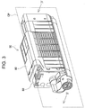
- FIG. 3 is a perspective view showing an external shape of the toner cartridge 50.
- the toner cartridge 50 includes a container main body 60 (i.e., a first storage member) and a lid member 80 (i.e., a second storage member or a side lid).
- the toner cartridge 50 is assembled by fitting the container main body 60 and the lid member 80 to each other, or by causing the container main body 60 and the lid member 80 to engage each other.
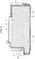
- FIGS. 4 and 5 are longitudinal sectional views of the toner cartridge 50 cut along a plane CP as seen in a direction indicated by an arrow IV.
- the toner T stored in the toner cartridge 50 is shown in FIG. 4 , but is omitted in FIG. 5 .
- FIG. 6 is a perspective view showing an external shape of the toner cartridge 50 before the container main body 60 and the lid member 80 are fitted to each other.
- a direction in which the container main body 60 is fitted into the lid member 80 is referred to as a fitting-in direction.
- the fitting-in direction is shown by an arrow F in FIG. 6 .
- the container main body 60 is a container for storing the toner T therein.
- the container main body 60 includes an inner space 61 that constitutes the toner storage chamber 50a, and an opening 62 leading to the inner space 61. More specifically, the container main body 60 includes a surrounding wall portion 63 that encloses the inner space 61 and extends in the fitting-in direction.
- the opening 62 is formed on an end of the surrounding wall portion 63 in the fitting-in direction.
- the opening 62 faces the fitting-in direction.
- a side wall portion 64 is formed on the other end of the surrounding wall portion 63. In other words, the side wall portion 64 closes the other end (i.e., an end opposite to the opening 62) of the surrounding wall portion 63.
- the container main body 60 has a substantially rectangular U-shaped cross section when cut along a plane perpendicular to the fitting-in direction.
- the container main body 60 includes a fitting-in portion 65 (i.e., a first fitting portion) fitted to the lid member 80. More specifically, the fitting-in portion 65 is fitted into inside of the lid member 80. The fitting-in portion 65 is formed on the end of the container main body 60 in the fitting-in direction (i.e., the same end as the opening 62).
- the toner ejection opening 50b is formed on the bottom of the container main body 60 (more specifically, the surrounding wall portion 63).
- the toner ejection opening 50b is provided for ejecting the toner T stored in the inner space 61.
- a shutter member 66 is provided on a lower part of the inner space 61. The shutter member 66 opens and closes the toner ejection opening 50b.
- a lever member 66A is fixed to the shutter member 66 for rotating the shutter member 66. By rotating the lever member 66A, the shutter member 66 rotates with respect to the container main body 60 to open and close the toner ejection opening 50b.
- the lid member 80 is fitted to the container main body 60 so as to close the inner space 61.
- the lid member 80 is mounted to the container main body 60 so as to close the opening 62. More specifically, the lid member 80 includes a side wall portion 81 facing the opening 62, and a surrounding wall portion 82 extending from a periphery of the side wall portion 81.
- the surrounding wall portion 82 extends in the fitting-in direction toward the container main body 60, and is fitted to the fitting-in portion 65.
- the lid member 80 has a substantially rectangular U-shaped cross section when cut along a plane perpendicular to the fitting-in direction.
- a sealing member 90 is provided between the container main body 60 and the lid member 80 for preventing leakage of the toner T in the inner space 61.
- the sealing member 90 seals between the container main body 60 and the lid member 80, and has a function to prevent leakage of the toner T from the toner cartridge 50.
- FIG. 7 is an enlarged view of a fitting section N which is shown by a dashed line in FIG. 5 .
- FIG. 8 is an enlarged view of the fitting section N ( FIG. 5 ) before the container main body 60 and the lid member 80 are fitted to each other.
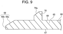
- FIG. 9 is an enlarged view showing a tip portion of the container main body 60 in the fitting section N.
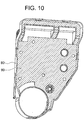
- FIG. 10 is a side view showing the lid member 80 to which the sealing member 90 is mounted as seen in the fitting-in direction shown by the arrow F in FIG. 6 . In FIG. 10 , the sealing member 90 is obliquely hatched. A fitting structure of the container main body 60 and the lid member 80 will be described with reference to FIGS. 7 through 10 .
- the surrounding wall 82 of the lid member 80 has a fitting surface 83 (i.e., a second fitting portion or an extending surface) to which the fitting-in portion 65 of the container main body 60 is fitted.
- the lid member 80 has a bottom surface 84 (i.e., a lid surface) facing the opening 62.
- the fitting surface 83 extends from the bottom surface 84 toward the container main body 60. In this example, the fitting surface 83 extends in the fitting-in direction.
- the bottom surface 84 is perpendicular to the fitting-in direction (in other words, perpendicular to the fitting surface 83).
- the fitting surface 83 is an inner wall surface of the surrounding wall portion 82.
- the bottom surface 84 is an inner wall surface of the side wall portion 81.
- the side wall portion 81 and the bottom surface 84 are formed at an end of the toner cartridge 50 in the fitting-in direction.
- the sealing member 90 is provided so as to contact the bottom surface 84 and the fitting surface 83 of the lid member 80.
- the sealing member 90 i.e., a resilient member
- the sealing member 90 is formed of a resilient material.
- the sealing member 90 is formed of a sponge.
- the sealing member 90 has a constant thickness, and is fixed (more specifically, bonded) to the bottom surface 84 of the lid member 80.
- the fitting-in portion 65 of the container main body 60 extends in the fitting-in direction.
- the fitting-in portion 65 includes an inner wall surface 67, a pressing surface 68 (i.e., a pressing portion) and an outer wall surface 69.
- the inner wall surface 67 extends toward the bottom surface 84 of the lid member 80.
- the inner wall surface 67 defines the inner space 61, and holds the toner T stored in the inner space 61.
- the inner wall surface 67 is parallel to the fitting surface 83.
- the inner wall surface 67 is perpendicular to the bottom surface 84.
- the pressing surface 68 is a surface pressed against the sealing member 90. More specifically, the pressing surface 68 is formed continuously with the inner wall surface 67. The pressing surface 68 contacts the sealing member 90 to compress the sealing member 90 between the pressing surface 68 and the lid member 80.
- the pressing surface 68 is an end surface of the container main body 60 located on the same side as the opening 62. In other words, the pressing surface 68 is formed on a downstream end of the container main body 60 in the fitting-in direction. Further, the pressing surface 68 is disposed downstream of a latch 70 (described later) in the fitting-in direction. A direction in which the pressing surface 68 presses the sealing member 90 is parallel to the fitting-in direction.
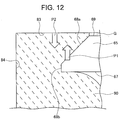
- the pressing surface 68 has an inclined surface 68a that faces the fitting surface 83 via the sealing member 90.
- the inclined surface 68a is inclined so that a distance between the inclined surface 68a and the fitting surface 83 increases toward the opening 62 (or toward the sealing member 90).
- the pressing surface 68 has a tip portion 68b (i.e., an end portion) disposed at a tip of the container maim body 60 facing the lid member 80.
- the pressing surface 68 contacts a contact surface 91 of the sealing member 90.
- the tip portion 68b is parallel to the contact surface 91 of the sealing member 90 before the sealing member 90 is compressed and deformed.
- the tip portion 68b is a plane that faces the bottom surface 84. Further, the tip portion 68b extends in a direction perpendicular to the fitting-in direction, the fitting surface 83 and the inner wall surface 67.
- the outer wall surface 69 is formed continuously with the pressing surface 68.
- the outer wall surface 69 is formed on a side opposite to the inner wall surface 67.
- the outer wall surface 69 faces the fitting surface 83 of the lid member 80.
- the outer wall surface 69 and the fitting surface 83 are disposed proximate to each other, and a gap G is formed between the outer wall surface 69 and the fitting surface 83.
- the gap G is isolated from the inner space 61 by the sealing member 90.
- the container main body 60 includes a latch 70 as a first engaging portion.
- the lid member 80 includes a hole 85 as a second engaging portion that engages the latch 70.
- the latch 70 and the hole 85 engage each other in a state where the sealing member 90 contacts the pressing surface 68. More specifically, when the latch 70 and the hole 85 engage each other, the pressing surface 68 contacts the sealing member 90 while compressing the sealing member 90.
- the latch 70 is a convex that protrudes from the outer wall surface 69 toward the fitting surface 83.
- the hole 85 is a concave receding from the fitting surface 83 in a direction away from the outer wall surface 69.
- the latch 70 has an inclined portion 70a.
- the inclined portion 70a is inclined with respect to the outer wall surface 69 so that a height (i.e., a protruding amount) from the outer wall surface 69 increases toward an upstream side in the fitting-in direction.
- the hole 85 is a through hole penetrating the surrounding wall portion 82. In this example, as shown in FIG. 6 , four latches 70 and four holes 85 are provided. However, the number of the latch (latches) 70 and the hole (holes) 85 are not limited.
- the container main body 60 has a facing surface 60a ( FIG. 6 ) formed on an upstream end of the fitting-in portion 65 in the fitting-in direction.
- the facing surface 60a faces and contacts an end portion 80a ( FIG. 6 ) of the lid member 80.
- the end portion 80a is formed on an upstream end of the lid member 80 in the fitting-in direction.
- an end of the hole 85 on an upstream side in the fitting-in direction is referred to as an upstream end 85a.
- An end of the latch 70 on the upstream side in the fitting-in direction (shown by the arrow F) is referred to as an upstream end 70c.
- "L1" indicates a distance from the contact surface 91 of the sealing member 90 to the upstream end 85a of the hole 85.
- "L2” indicates a distance from the tip portion 68b to the upstream end 70c of the latch 70.
- the distance L1 is shorter than the distance L2 (i.e., L1 ⁇ L2). Therefore, while the container main body 60 and the lid member 80 are being fitted to each other, the tip portion 68b contacts the contact surface 91 of the sealing member 90 before the latch 70 engages the hole 85.
- a printing operation of the image forming apparatus 100 will be described with reference to FIG. 1 .
- the image forming apparatus 100 When the image forming apparatus 100 receives print command from a host device (not shown), the image forming apparatus 100 causes the medium feeding unit 13 to feed the recording medium from the medium cassette 11.
- the medium conveying rollers 15 and 16 convey the recording medium along the medium conveying path 10 toward the transfer belt unit 20.
- the detection unit 14 detects the thickness of the recording medium.
- the transfer belt 21 coveys the recording medium in the direction shown by the arrow C.
- the transfer belt 21 conveys the recording medium to the fixing unit 40, and the fixing unit 40 fixes the toner image to the recording surface of the recording medium.
- the medium conveying rollers 17 and 18 convey the recording medium to the stacker 12.
- a toner image formation in the above described printing operation will be described with reference to FIG. 2 .
- the toner image formation described below is controlled by, for example, a control unit (not shown) of the image forming apparatus 100.
- the photosensitive body 31 rotates in the direction indicated by the arrow R1.
- the surface of the photosensitive body 31 is uniformly charged by the charging roller 32.
- the surface of the photosensitive body 31 is exposed with light emitted by the exposure unit 33 so that a latent image is formed on the surface of the photosensitive body 31 according to image information.
- the toner T is supplied from the toner cartridge 50 and is held in the toner reservoir 51.
- the toner T is supplied by the toner supplying roller 52 to the developing roller 54.
- the toner T supplied to the developing roller 54 is formed into the thin toner layer having a constant thickness by the developing blade 53.
- the latent image on the surface of the photosensitive body 31 is developed by the toner T on the surface of the developing roller 54, and a toner image (i.e., a developer image) is formed on the surface of the photosensitive body 31.
- the toner image on the surface of the photosensitive body 31 is transferred to the recording medium P by the electrical potential difference between the photosensitive body 31 and the transfer roller 35.
- the residual toner that remains on the surface of the photosensitive body 31 after the toner image is transferred to the recording medium P is removed by the cleaning blade 36a, and is collected in the waste toner collection unit 36b.
- the toner cartridge 50 is in a state shown in FIG. 6 .
- the container main body 60 is moved in the fitting-in direction as shown by the arrow F, and the fitting-in portion 65 at the end of the container main body 60 is fitted into inside of the lid member 80.
- This causes the latch 70 to engage the hole 85.
- the container main body 60 and the lid member 80 are fitted to each other as shown in FIG. 3 .
- the end portion 80a ( FIG. 6 ) of the lid member 80 faces or contacts the facing surface 60a ( FIG. 6 ) of the container main body 60.
- the container main body 60 and the lid member 80 are in a state shown in FIG. 8 . From this state, when the container main body 60 is moved in the fitting-in direction as shown by the arrow F, the tip portion of the fitting-in portion 65 moves into the lid member 80. The inclined surface 70a of the latch 70 contacts the end portion 80a of the lid member 80. When the container main body 60 is further moved in the fitting-in direction, the fitting-in portion 65 further moves into the lid member 80 while the inclined surfaces 70a contacts the end portion 80a. In this state, the container main body 60 is resiliently deformed in a direction in which the pressing surface 68 moves away from the fitting surface 83 by a pushing force from the lid member 80.
- the container main body 60 is further moved in the fitting-in direction while a top portion 70b of the latch 70 slides along the fitting surface 83. Then, the pressing surface 68 contacts the sealing member 90 while the container main body 60 is resiliently deformed as shown in FIG. 11 .
- the pressing surface 68 is pressed against the sealing member 90 while compressing the sealing member 90, and the latch 70 engages the hole 85.
- the container main body 60 is released from the pushing force from the lid member 80. Therefore, the container main body 60 moves in a direction in which the pressing surface 68 moves toward the fitting surface 83 by a resilient restoring force of the container main body 60. As a result, the container main body 60 restores its original shape as shown in FIG. 7 , and the lid member 80 and the container main body 60 are fixed to each other.
- a gap between the fitting-in portion 65a and the fitting surface 83 is smaller when the latch 70 engages the hole 85 (i.e., when the container main body 60 and the lid member 80 are completely fitted to each other) than while the container main body 60 and the lid member 80 are being fitted to each other.
- the sealing member 90 is compressed by the tip portion 68b of the pressing surface 68 in the fitting-in direction, and is applied with a pressure P1 in a direction from the inclined surface 68a toward the fitting surface 83.
- the sealing member 90 is also applied with a pressure P2 (i.e., a reactive force from the fitting surface 83) in a direction from the fitting surface 83 toward the inclined surface 68a. Therefore, the sealing member 90 is compressed with a high pressure between the inclined surface 68a and the fitting surface 83.
- the inclined surface 68a and the sealing member 90 contact each other with a high pressure.
- the inclined surface 68a faces the fitting surface 83 and also faces the bottom surface 84, and therefore the sealing member 90 is compressed between the fitting surface 83 and the bottom surface 84.
- the toner T may mainly move through a contact portion between the pressing surface 68 and the sealing member 90, move through the gap G, and reach the outside of the toner cartridge 50 through the hole 85.
- the sealing member 90 is compressed between the inclined surface 68a and the fitting surface 83, and the inclined surface 68a contacts the sealing member 90 with a high pressure. Therefore, a leakage path of the toner T leading to the gap G is closed. Thus, the leakage of the toner T is prevented.
- FIG. 13 is a schematic view showing a fitting section of a toner cartridge according to Comparison Example.
- components corresponding to those of Embodiment 1 are assigned the same reference numerals.
- the pressing surface 68 has a plane surface perpendicular to the fitting surface 83, but does not have the inclined surface 68a.
- the seal member 90 is applied with a pressure P3 in a direction away from the fitting surface 83.
- the seal member 90 is not applied with a force P1 as shown in FIG. 12 in a direction toward the fitting surface 83. Therefore, the sealing member 90 is deformed as shown in FIG. 13 by the pressure P3 so that the sealing member 90 moves away from the fitting surface 83.
- Such a deformation of the sealing member 90 may deteriorate the sealing performance, and may cause the leakage of the toner T. Further, in the configuration shown in FIG.
- the sealing member 90 when the pressing surface 68 is pressed against the sealing member 90, the sealing member 90 may escape downward from a portion between the pressing surface 68 and the lid member 80, and a contact pressure between the pressing surface 68 and the sealing member 90 may decrease. Further, an area (i.e., a contact area) at which the pressing surface 68 contacts the sealing member 90 may also decrease. Such decrease in contact pressure and contact area may cause the leakage of the toner.
- the seal member 90 is pressed against the fitting surface 83 by the pressure P1 in the direction toward the fitting surface 83 as shown in FIG. 12 , and therefore the sealing member 90 is prevented from moving away from the fitting surface 83, with the result that the sealing performance is ensured.
- the inclined surface 68a presses the sealing member 90 against the fitting surface 83, and therefore the sealing member 90 is prevented from escaping. Accordingly, the decrease in contact pressure and contact area is prevented.
- FIG. 14 is a schematic view showing a fitting section of a toner cartridge according to another Comparison Example.
- components corresponding to those of Embodiment 1 are assigned the same reference numerals.
- the lid member 80 has no fitting surface 83. Therefore, the seal member 90 is applied with a pressure P4 by the inclined surface 68a, but is not applied with a pressure in a direction from the fitting surface 83 toward the inclined surface 68a (see, the pressure P2 shown in FIG. 12 ). Accordingly, a pressure between the sealing member 90 and the inclined surface 68a becomes low, and therefore a high sealing performance is not achieved.
- the lid member 80 has the fitting surface 83, and therefore the seal member 90 is applied with the pressure P2 in the direction from the fitting surface 83 toward the inclined surface 68a as shown in FIG. 12 . Therefore, the pressure between the sealing member 90 and the inclined surface 68a becomes high, and a high sealing performance is achieved.
- fitting-in portion 65 and the fitting surface 83 are disposed proximate to each other. With such an arrangement, the pressure applied to the sealing member 90 between the fitting surface 83 and the inclined surface 68a increases, and the sealing performance is enhanced.
- Embodiment 1 of the present invention provides the following advantages (1) through (4).
- FIG. 15 shows a first modification of the pressing surface 68.
- the inner wall surface 67 and the inclined surface 68a are continuously formed.
- the tip portion 68b is configured as an acute-angled portion between the inner wall surface 67 and the inclined surface 68a.
- FIG. 16 shows a second modification of the pressing surface 68.
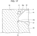
- the pressing surface 68 includes an inclined surface 68c (i.e., a second inclined surface) in addition to the inclined surface 68a (i.e., a first inclined surface).
- the inclined surface 68a is formed so as to face the fitting surface 83, and the inclined surface 68c is formed on a side opposite to the inclined surface 68a.
- the inclined surface 68c is inclined so that a distance between the inclined surface 68c and the fitting surface 83 decreases toward the opening 62.
- the inclined surface 68a has a larger area than the inclined surface 68c.
- the inclined surface 68a of the pressing surface 68 is a flat surface.
- the inclined surface 68a can be a curved surface.
- FIGS. 18 and 19 show third and fourth modifications of the pressing surface 68.
- the inclined surface 68a of the pressing surface 68 is a curved convex surface.
- the inclined surface 68a of the pressing surface 68 is a curved concave surface.
- both of the inclined surfaces 68a and 68c are flat surfaces.
- the inclined surfaces 68a and 68c can be curved surfaces.
- FIG. 20 shows a fifth modification of the pressing surface 68.
- the inclined surfaces 68a and 68c of the pressing surface 68 are curved surfaces (more specifically, curved convex surfaces).
- FIGS. 21 and 22 show sixth and seventh modifications of the pressing surface 68.
- the inclined surface 68a is a flat surface
- the inclined surface 68c is a curved surface (more specifically, curved convex surfaces).
- the inclined surface 68a is a curved surface (more specifically, curved convex surfaces), and the inclined surface 68c is a flat surface.
- the inclined surface 68a has a larger area than the inclined surface 68c.
- FIG. 23 is a schematic view showing a configuration of a fitting section N of a toner cartridge 50 according to Embodiment 2.
- the fitting section N shown in FIG. 23 corresponds to the fitting section N shown by the dashed line in FIG. 5 .
- the toner cartridge 50 of Embodiment 2 is different from the toner cartridge 50 in that an inclined surface 86 is provided on the lid member 80.
- Other components of Embodiment 2 are the same as those of Embodiment 1.
- components which are the same as those of Embodiment 1 are assigned the same reference numerals, and explanations thereof will be omitted or simplified.
- the lid member 80 has the inclined surface 86 facing the inclined surface 68a of the container main body 60.
- the inclined surface 86 is inclined so that a distance between the inclined surface 86 and the fitting surface 83 decreases toward the container main body 60.
- the inclined surface 86 is provided between the fitting surface 83 and the bottom surface 84 so as to connect the fitting surface 83 and the bottom surface 84.
- the inclined surface 86 is parallel to the inclined surface 68a of the container main body 60.
- the inclined surface 86 shown in FIG. 23 is a flat surface, the inclined surface 86 can be a curved surface.
- the sealing member 90 is compressed between the inclined surface 68a and the inclined surface 86. Therefore, the sealing member 90 and the inclined surface 68a are pressed against each other with a higher pressure, as compared with a configuration in which the inclined surface 86 is not provided. Thus, the sealing performance can be enhanced.
- FIG. 24 is a schematic view showing a configuration of a fitting section N of a toner cartridge 50 according to Embodiment 3.
- the fitting section N shown in FIG. 24 corresponds to the fitting section N shown by the dashed line in FIG. 5 .
- the toner cartridge 50 of Embodiment 3 is different from the toner cartridge 50 in that an inclined surface 87 is provided on the lid member 80.
- Other components of Embodiment 3 are the same as those of Embodiment 1.
- components which are the same as those of Embodiment 1 are assigned the same reference numerals, and explanations thereof will be omitted or simplified.
- the lid member 80 has the inclined surface 87 facing the fitting surface 83.
- the inclined surface 87 is inclined so that a distance between the inclined surface 87 and the fitting surface 83 increases toward the container main body 60.
- the inclined surface 87 is provided so as to protrude from the bottom surface 84 toward the container main body 60.
- the inclined surface 87 shown in FIG. 24 is a flat surface, the inclined surface 87 can be a curved surface.
- the pressing surface 68 of the container main body 60 does not have the inclined surface 68a. That is, the pressing surface 68 is a surface perpendicular to the fitting surface 83 (in other words, perpendicular to the fitting-in direction).
- Embodiment 3 when the sealing member 90 is compressed by being pressed by the pressing surface 68, the sealing member 90 is applied with a pressure P5 by the inclined surface 87 in a direction toward the fitting surface 83. With the pressure P5, the sealing member 90 is pressed against the fitting surface 83. Therefore, the sealing performance can be enhanced, as compared with the Comparison Example shown in FIG. 13 .
- FIG. 25 shows a modification of the fitting section N of the toner cartridge 50 according to Embodiment 3.
- the lid member 80 has the inclined surface 87
- the pressing surface 68 has the inclined surface 68a.
- parallel is intended to mean generally or substantially parallel.
- perpendicular is intended to mean generally or substantially perpendicular.
- the container main body 60 and the lid member 80 are fitted to each other or engaged with each other.
- the container main body 60 and the lid member 80 are fixed to each other using bonding or screws.
- the printer has been described as an example of the image forming apparatus.
- the present invention is applicable to a copier, a facsimile machine, a MFP (Multi-Function Peripheral) or other image forming apparatus.
Landscapes
- Physics & Mathematics (AREA)
- General Physics & Mathematics (AREA)
- Dry Development In Electrophotography (AREA)
Claims (12)
- Entwicklerspeicherbehälter (50), umfassend:ein erstes Speicherelement (60), das einen Entwickler speichert;ein zweites Speicherelement (80), das an dem ersten Speicherbehälter (60) angebracht ist; undein Dichtungselement (90), das zwischen dem ersten Speicherelement (60) und dem zweiten Speicherelement (80) abdichtet, um ein Austreten des Entwicklers zu verhindern;wobei das erste Speicherelement (60) einen ersten Passteil (65) aufweist;wobei das Speicherelement (80) eine Passfläche (83) aufweist, an welcher der erste Passteil (65) angebracht ist;wobei der erste Passteil (65) einen ersten Pressteil (68) aufweist, der das Dichtungselement (90) presst; wobei der Pressteil (68) einen schrägen Teil (68a) aufweist, der zu der Passfläche (83) zeigt;wobei der erste Passteil (65) ferner eine Außenwand (69) aufweist, die kontinuierlich mit dem schrägen Teil (68a) des Pressteils (68) ausgebildet ist, wobei die Außenwand (69) und die Passfläche (83) zueinander zeigen und parallel zueinander sind.
- Entwicklerspeicherbehälter (50) nach Anspruch 1, wobei der schräge Teil (68a) so geneigt ist, dass ein Abstand zwischen dem schrägen Teil (68a) und der Passfläche (83) in Richtung des Dichtungselements (90) zunimmt.
- Entwicklerspeicherbehälter (50) nach Anspruch 1 oder 2, wobei der Pressteil (68) einen Spitzenteil (68b) aufweist, der das Dichtungselement (90) berührt, und
wobei sich der Spitzenteil (68b) in eine Richtung erstreckt, die in einem Zustand bevor das Dichtungselement (90) durch Pressen durch den Pressteil (68) im Wesentlichen parallel ist zu einer Oberfläche (91) des Dichtungselement (90). - Entwicklerspeicherbehälter (50) nach einem der Ansprüche 1 bis 3, wobei das erste Speicherelement (60) einen ersten Eingriffsteil (70) aufweist;
wobei das zweite Speicherelement (80) einen zweiten Eingriffsteil (85) aufweist, der mit dem ersten Eingriffsteil (70) eingreift; und
wobei der erste Eingriffsteil (70) in einem Zustand mit dem zweiten Eingriffsteil (85) eingreift, in dem sich das Dichtungselement (90) und das Presselement (68) gegenseitig berühren. - Entwicklerspeicherbehälter (50) nach Anspruch 4, wobei der erste Eingriffsteil (70) von dem ersten Passteil (65) vorsteht, und
wobei ein Abstand zwischen dem ersten Passteil (65) und der Passfläche (83), wenn das erste Speicherelement (60) und das zweite Speicherelement (80) aneinander angebracht sind, kleiner ist als der Abstand zwischen dem ersten Passteil (65) und der Passfläche (83), während das erste Speicherelement (60) und das zweite Speicherelement (80) aneinander angebracht werden. - Entwicklerspeicherbehälter (50) nach einem der Ansprüche 1 bis 5, wobei der Pressteil (68) keinen schrägen Teil aufweist, der geneigt ist, so dass ein Abstand zwischen dem schrägen Teil und der Passfläche (83) in Richtung des Dichtungselements (90) zunimmt.
- Entwicklerspeicherbehälter (50) nach einem der Ansprüche 1 bis 5, wobei der schräge Teil (68a) des Pressteils (68) ein erster schräger Teil (68a) ist;
wobei der Pressteil (68) ferner einen zweiten schrägen Teil (68c) aufweist, der sich auf einer Seite befindet, die zu dem ersten schrägen Teil (68a) entgegengesetzt ist; und
wobei der zweite schräge Teil (68c) so geneigt ist, dass ein Abstand zwischen dem zweiten schrägen Teil (68c) und der Passfläche (83) in Richtung des Dichtungselements (90) abnimmt. - Entwicklerspeicherbehälter (50) nach Anspruch 7, wobei der erste schräge Teil (68a) eine größere Fläche aufweist als der zweite schräge Teil (68c).
- Entwicklerspeicherbehälter (50) nach einem der Ansprüche 1 bis 8, wobei das zweite Speicherelement (80) eine schräge Oberfläche (86) aufweist, die zu dem schrägen Teil (68a) des Pressteils (68) zeigt; und
wobei die schräge Oberfläche (86) so geneigt ist, dass ein Abstand zwischen der schrägen Oberfläche (86) und der Passfläche (83) in Richtung des ersten Speicherelements (60) zunimmt. - Entwicklerspeicherbehälter (50) nach einem der Ansprüche 1 bis 9, wobei das zweite Speicherelement (80) eine schräge Oberfläche (87) aufweist, die zu der Passfläche (83) zeigt; und
wobei die schräge Oberfläche (87) so geneigt ist, dass ein Abstand zwischen der schrägen Oberfläche (87) und der Passfläche (83) in Richtung des ersten Speicherelements (60) zunimmt. - Entwicklungsvorrichtung (34), die folgendes umfasst:den Entwicklerspeicherbehälter (50) nach einem der Ansprüche 1 bis 10; undein Entwicklungselement (54), das ein latentes Bild unter Verwendung des durch den Entwicklerspeicherbehälter (50) zugeführten Entwicklers entwickelt.
- Bilderzeugende Vorrichtung (100), die folgendes umfasst:einen Bildträgerkörper (31);eine Einheit (33) zur Erzeugung eines latenten Bilds, welche ein latentes Bild an dem Bildträgerkörper (31) erzeugt;den Entwicklerspeicherbehälter (50) nach einem der Ansprüche 1 bis 10; undein Entwicklungselement (54), das ein latentes Bild unter Verwendung des durch den Entwicklerspeicherbehälter (50) zugeführten Entwicklers entwickelt.
Applications Claiming Priority (1)
| Application Number | Priority Date | Filing Date | Title |
|---|---|---|---|
| JP2013036838A JP5785969B2 (ja) | 2013-02-27 | 2013-02-27 | 現像剤収容器、現像装置、及び画像形成装置 |
Publications (3)
| Publication Number | Publication Date |
|---|---|
| EP2772807A2 EP2772807A2 (de) | 2014-09-03 |
| EP2772807A3 EP2772807A3 (de) | 2017-04-05 |
| EP2772807B1 true EP2772807B1 (de) | 2020-04-22 |
Family
ID=50238102
Family Applications (1)
| Application Number | Title | Priority Date | Filing Date |
|---|---|---|---|
| EP14155901.3A Not-in-force EP2772807B1 (de) | 2013-02-27 | 2014-02-20 | Entwicklervorratskartusche, Entwicklervorrichtung und Bilderzeugungsvorrichtung |
Country Status (4)
| Country | Link |
|---|---|
| US (1) | US20140241752A1 (de) |
| EP (1) | EP2772807B1 (de) |
| JP (1) | JP5785969B2 (de) |
| CN (1) | CN104007639B (de) |
Families Citing this family (3)
| Publication number | Priority date | Publication date | Assignee | Title |
|---|---|---|---|---|
| JP6242300B2 (ja) * | 2014-06-25 | 2017-12-06 | 三菱電機株式会社 | 空気調和装置の室内機及び空気調和装置 |
| JP6477043B2 (ja) * | 2015-03-06 | 2019-03-06 | 富士ゼロックス株式会社 | 画像形成装置および現像剤の収容容器 |
| CN110488584B (zh) * | 2019-09-19 | 2022-05-17 | 珠海市源呈数码科技有限公司 | 显影盒壳体和显影盒 |
Family Cites Families (15)
| Publication number | Priority date | Publication date | Assignee | Title |
|---|---|---|---|---|
| JPH04184377A (ja) * | 1990-11-20 | 1992-07-01 | Canon Inc | 現像剤補給容器 |
| JPH08146734A (ja) * | 1994-11-17 | 1996-06-07 | Canon Inc | 現像剤補給容器 |
| JPH11161012A (ja) * | 1997-11-25 | 1999-06-18 | Seiko Epson Corp | 現像装置 |
| JP3628539B2 (ja) * | 1999-01-25 | 2005-03-16 | 株式会社リコー | トナー容器 |
| JP4681762B2 (ja) * | 2001-06-18 | 2011-05-11 | キヤノン株式会社 | カートリッジ |
| JP2003015391A (ja) * | 2001-06-29 | 2003-01-17 | Fuji Xerox Co Ltd | 現像剤収容構造体 |
| JP3861656B2 (ja) * | 2001-10-29 | 2006-12-20 | セイコーエプソン株式会社 | トナー容器 |
| MXPA06012659A (es) * | 2005-04-27 | 2007-01-16 | Ricoh Kk | Recipiente de toner y aparato formador de imagen. |
| JP4315933B2 (ja) * | 2005-07-21 | 2009-08-19 | 株式会社沖データ | 現像剤カートリッジ、現像装置、及び画像形成装置 |
| JP4689422B2 (ja) * | 2005-09-27 | 2011-05-25 | 株式会社沖データ | 現像剤カートリッジ、画像形成ユニット及び画像形成装置 |
| JP5103895B2 (ja) * | 2006-12-25 | 2012-12-19 | 富士ゼロックス株式会社 | 現像剤収容容器、並びに現像剤収容容器の組立て方法及び再生方法 |
| JP2008256895A (ja) * | 2007-04-04 | 2008-10-23 | Matsushita Electric Ind Co Ltd | 現像剤貯蔵装置およびこれを用いた画像形成装置 |
| JP4598089B2 (ja) * | 2008-01-24 | 2010-12-15 | 株式会社沖データ | 現像剤収容器及び画像形成装置 |
| JP5172588B2 (ja) * | 2008-10-14 | 2013-03-27 | 京セラドキュメントソリューションズ株式会社 | トナーコンテナ |
| JP5218141B2 (ja) * | 2009-02-20 | 2013-06-26 | ブラザー工業株式会社 | 現像装置、現像カートリッジ、プロセスカートリッジおよび画像形成装置 |
-
2013
- 2013-02-27 JP JP2013036838A patent/JP5785969B2/ja active Active
-
2014
- 2014-02-20 EP EP14155901.3A patent/EP2772807B1/de not_active Not-in-force
- 2014-02-25 US US14/189,498 patent/US20140241752A1/en not_active Abandoned
- 2014-02-27 CN CN201410068248.1A patent/CN104007639B/zh active Active
Non-Patent Citations (1)
| Title |
|---|
| None * |
Also Published As
| Publication number | Publication date |
|---|---|
| JP5785969B2 (ja) | 2015-09-30 |
| EP2772807A2 (de) | 2014-09-03 |
| EP2772807A3 (de) | 2017-04-05 |
| CN104007639B (zh) | 2020-08-11 |
| JP2014164214A (ja) | 2014-09-08 |
| CN104007639A (zh) | 2014-08-27 |
| US20140241752A1 (en) | 2014-08-28 |
Similar Documents
| Publication | Publication Date | Title |
|---|---|---|
| US7949287B2 (en) | Developer cartridge, image forming unit and image forming apparatus | |
| US8165505B2 (en) | Developer cartridge adapted to restrict leakage of developer | |
| JP5110866B2 (ja) | プロセスカートリッジと画像形成装置 | |
| US8000630B2 (en) | Developing cartridge, process cartridge, and electrophotographic image forming apparatus | |
| US20110052256A1 (en) | Image forming apparatus | |
| US20090136259A1 (en) | Developer collection container, developer cartridge, developing unit and image forming apparatus | |
| US8787803B2 (en) | Developing device, image forming unit and image forming apparatus | |
| US8594539B2 (en) | Outlet recess for a powder container for an image forming apparatus | |
| US20120099887A1 (en) | Image forming apparatus | |
| US8983342B2 (en) | Developer storage container, image forming unit and image forming apparatus | |
| US8849164B2 (en) | Developer storage body, developing device and image forming apparatus | |
| US20080193169A1 (en) | Developer container and image forming apparatus that incorporates the developer container | |
| JP4538026B2 (ja) | 帯電装置、画像形成ユニット及び画像形成装置 | |
| EP2772807B1 (de) | Entwicklervorratskartusche, Entwicklervorrichtung und Bilderzeugungsvorrichtung | |
| JP5250596B2 (ja) | 画像形成ユニット及び画像形成装置 | |
| JP5495933B2 (ja) | 現像剤収容装置、現像装置及び現像剤補給装置 | |
| US20120099892A1 (en) | Attaching and detaching body and image forming apparatus | |
| US8655236B2 (en) | Developer storage body, image forming unit and image forming apparatus | |
| JP7585950B2 (ja) | 現像装置、およびそれを備えた画像形成装置 | |
| JP5771552B2 (ja) | 現像剤収納容器、現像装置及び画像形成装置 | |
| JP2009204999A (ja) | トナー補給回収装置および画像形成装置 | |
| JP2011169956A (ja) | トナーカートリッジ、プロセスカートリッジ及び画像形成装置 |
Legal Events
| Date | Code | Title | Description |
|---|---|---|---|
| PUAI | Public reference made under article 153(3) epc to a published international application that has entered the european phase |
Free format text: ORIGINAL CODE: 0009012 |
|
| 17P | Request for examination filed |
Effective date: 20140220 |
|
| AK | Designated contracting states |
Kind code of ref document: A2 Designated state(s): AL AT BE BG CH CY CZ DE DK EE ES FI FR GB GR HR HU IE IS IT LI LT LU LV MC MK MT NL NO PL PT RO RS SE SI SK SM TR |
|
| AX | Request for extension of the european patent |
Extension state: BA ME |
|
| PUAL | Search report despatched |
Free format text: ORIGINAL CODE: 0009013 |
|
| AK | Designated contracting states |
Kind code of ref document: A3 Designated state(s): AL AT BE BG CH CY CZ DE DK EE ES FI FR GB GR HR HU IE IS IT LI LT LU LV MC MK MT NL NO PL PT RO RS SE SI SK SM TR |
|
| AX | Request for extension of the european patent |
Extension state: BA ME |
|
| RIC1 | Information provided on ipc code assigned before grant |
Ipc: G03G 15/08 20060101AFI20170301BHEP |
|
| STAA | Information on the status of an ep patent application or granted ep patent |
Free format text: STATUS: REQUEST FOR EXAMINATION WAS MADE |
|
| R17P | Request for examination filed (corrected) |
Effective date: 20171003 |
|
| RBV | Designated contracting states (corrected) |
Designated state(s): AL AT BE BG CH CY CZ DE DK EE ES FI FR GB GR HR HU IE IS IT LI LT LU LV MC MK MT NL NO PL PT RO RS SE SI SK SM TR |
|
| GRAP | Despatch of communication of intention to grant a patent |
Free format text: ORIGINAL CODE: EPIDOSNIGR1 |
|
| STAA | Information on the status of an ep patent application or granted ep patent |
Free format text: STATUS: GRANT OF PATENT IS INTENDED |
|
| INTG | Intention to grant announced |
Effective date: 20191220 |
|
| GRAS | Grant fee paid |
Free format text: ORIGINAL CODE: EPIDOSNIGR3 |
|
| GRAA | (expected) grant |
Free format text: ORIGINAL CODE: 0009210 |
|
| STAA | Information on the status of an ep patent application or granted ep patent |
Free format text: STATUS: THE PATENT HAS BEEN GRANTED |
|
| AK | Designated contracting states |
Kind code of ref document: B1 Designated state(s): AL AT BE BG CH CY CZ DE DK EE ES FI FR GB GR HR HU IE IS IT LI LT LU LV MC MK MT NL NO PL PT RO RS SE SI SK SM TR |
|
| REG | Reference to a national code |
Ref country code: GB Ref legal event code: FG4D |
|
| REG | Reference to a national code |
Ref country code: CH Ref legal event code: EP |
|
| REG | Reference to a national code |
Ref country code: IE Ref legal event code: FG4D |
|
| REG | Reference to a national code |
Ref country code: DE Ref legal event code: R096 Ref document number: 602014064002 Country of ref document: DE |
|
| REG | Reference to a national code |
Ref country code: AT Ref legal event code: REF Ref document number: 1260927 Country of ref document: AT Kind code of ref document: T Effective date: 20200515 |
|
| REG | Reference to a national code |
Ref country code: NL Ref legal event code: FP |
|
| REG | Reference to a national code |
Ref country code: LT Ref legal event code: MG4D |
|
| REG | Reference to a national code |
Ref country code: DE Ref legal event code: R082 Ref document number: 602014064002 Country of ref document: DE Representative=s name: VENNER SHIPLEY GERMANY LLP, DE Ref country code: DE Ref legal event code: R082 Ref document number: 602014064002 Country of ref document: DE Representative=s name: VENNER SHIPLEY LLP, DE |
|
| PG25 | Lapsed in a contracting state [announced via postgrant information from national office to epo] |
Ref country code: GR Free format text: LAPSE BECAUSE OF FAILURE TO SUBMIT A TRANSLATION OF THE DESCRIPTION OR TO PAY THE FEE WITHIN THE PRESCRIBED TIME-LIMIT Effective date: 20200723 Ref country code: NO Free format text: LAPSE BECAUSE OF FAILURE TO SUBMIT A TRANSLATION OF THE DESCRIPTION OR TO PAY THE FEE WITHIN THE PRESCRIBED TIME-LIMIT Effective date: 20200722 Ref country code: FI Free format text: LAPSE BECAUSE OF FAILURE TO SUBMIT A TRANSLATION OF THE DESCRIPTION OR TO PAY THE FEE WITHIN THE PRESCRIBED TIME-LIMIT Effective date: 20200422 Ref country code: SE Free format text: LAPSE BECAUSE OF FAILURE TO SUBMIT A TRANSLATION OF THE DESCRIPTION OR TO PAY THE FEE WITHIN THE PRESCRIBED TIME-LIMIT Effective date: 20200422 Ref country code: PT Free format text: LAPSE BECAUSE OF FAILURE TO SUBMIT A TRANSLATION OF THE DESCRIPTION OR TO PAY THE FEE WITHIN THE PRESCRIBED TIME-LIMIT Effective date: 20200824 Ref country code: LT Free format text: LAPSE BECAUSE OF FAILURE TO SUBMIT A TRANSLATION OF THE DESCRIPTION OR TO PAY THE FEE WITHIN THE PRESCRIBED TIME-LIMIT Effective date: 20200422 Ref country code: IS Free format text: LAPSE BECAUSE OF FAILURE TO SUBMIT A TRANSLATION OF THE DESCRIPTION OR TO PAY THE FEE WITHIN THE PRESCRIBED TIME-LIMIT Effective date: 20200822 |
|
| REG | Reference to a national code |
Ref country code: AT Ref legal event code: MK05 Ref document number: 1260927 Country of ref document: AT Kind code of ref document: T Effective date: 20200422 |
|
| PG25 | Lapsed in a contracting state [announced via postgrant information from national office to epo] |
Ref country code: HR Free format text: LAPSE BECAUSE OF FAILURE TO SUBMIT A TRANSLATION OF THE DESCRIPTION OR TO PAY THE FEE WITHIN THE PRESCRIBED TIME-LIMIT Effective date: 20200422 Ref country code: LV Free format text: LAPSE BECAUSE OF FAILURE TO SUBMIT A TRANSLATION OF THE DESCRIPTION OR TO PAY THE FEE WITHIN THE PRESCRIBED TIME-LIMIT Effective date: 20200422 Ref country code: RS Free format text: LAPSE BECAUSE OF FAILURE TO SUBMIT A TRANSLATION OF THE DESCRIPTION OR TO PAY THE FEE WITHIN THE PRESCRIBED TIME-LIMIT Effective date: 20200422 Ref country code: BG Free format text: LAPSE BECAUSE OF FAILURE TO SUBMIT A TRANSLATION OF THE DESCRIPTION OR TO PAY THE FEE WITHIN THE PRESCRIBED TIME-LIMIT Effective date: 20200722 |
|
| PG25 | Lapsed in a contracting state [announced via postgrant information from national office to epo] |
Ref country code: AL Free format text: LAPSE BECAUSE OF FAILURE TO SUBMIT A TRANSLATION OF THE DESCRIPTION OR TO PAY THE FEE WITHIN THE PRESCRIBED TIME-LIMIT Effective date: 20200422 |
|
| REG | Reference to a national code |
Ref country code: DE Ref legal event code: R097 Ref document number: 602014064002 Country of ref document: DE |
|
| PG25 | Lapsed in a contracting state [announced via postgrant information from national office to epo] |
Ref country code: ES Free format text: LAPSE BECAUSE OF FAILURE TO SUBMIT A TRANSLATION OF THE DESCRIPTION OR TO PAY THE FEE WITHIN THE PRESCRIBED TIME-LIMIT Effective date: 20200422 Ref country code: CZ Free format text: LAPSE BECAUSE OF FAILURE TO SUBMIT A TRANSLATION OF THE DESCRIPTION OR TO PAY THE FEE WITHIN THE PRESCRIBED TIME-LIMIT Effective date: 20200422 Ref country code: AT Free format text: LAPSE BECAUSE OF FAILURE TO SUBMIT A TRANSLATION OF THE DESCRIPTION OR TO PAY THE FEE WITHIN THE PRESCRIBED TIME-LIMIT Effective date: 20200422 Ref country code: RO Free format text: LAPSE BECAUSE OF FAILURE TO SUBMIT A TRANSLATION OF THE DESCRIPTION OR TO PAY THE FEE WITHIN THE PRESCRIBED TIME-LIMIT Effective date: 20200422 Ref country code: IT Free format text: LAPSE BECAUSE OF FAILURE TO SUBMIT A TRANSLATION OF THE DESCRIPTION OR TO PAY THE FEE WITHIN THE PRESCRIBED TIME-LIMIT Effective date: 20200422 Ref country code: DK Free format text: LAPSE BECAUSE OF FAILURE TO SUBMIT A TRANSLATION OF THE DESCRIPTION OR TO PAY THE FEE WITHIN THE PRESCRIBED TIME-LIMIT Effective date: 20200422 Ref country code: SM Free format text: LAPSE BECAUSE OF FAILURE TO SUBMIT A TRANSLATION OF THE DESCRIPTION OR TO PAY THE FEE WITHIN THE PRESCRIBED TIME-LIMIT Effective date: 20200422 Ref country code: EE Free format text: LAPSE BECAUSE OF FAILURE TO SUBMIT A TRANSLATION OF THE DESCRIPTION OR TO PAY THE FEE WITHIN THE PRESCRIBED TIME-LIMIT Effective date: 20200422 |
|
| PG25 | Lapsed in a contracting state [announced via postgrant information from national office to epo] |
Ref country code: SK Free format text: LAPSE BECAUSE OF FAILURE TO SUBMIT A TRANSLATION OF THE DESCRIPTION OR TO PAY THE FEE WITHIN THE PRESCRIBED TIME-LIMIT Effective date: 20200422 Ref country code: PL Free format text: LAPSE BECAUSE OF FAILURE TO SUBMIT A TRANSLATION OF THE DESCRIPTION OR TO PAY THE FEE WITHIN THE PRESCRIBED TIME-LIMIT Effective date: 20200422 |
|
| PLBE | No opposition filed within time limit |
Free format text: ORIGINAL CODE: 0009261 |
|
| STAA | Information on the status of an ep patent application or granted ep patent |
Free format text: STATUS: NO OPPOSITION FILED WITHIN TIME LIMIT |
|
| 26N | No opposition filed |
Effective date: 20210125 |
|
| PGFP | Annual fee paid to national office [announced via postgrant information from national office to epo] |
Ref country code: NL Payment date: 20210113 Year of fee payment: 8 Ref country code: FR Payment date: 20210113 Year of fee payment: 8 |
|
| PG25 | Lapsed in a contracting state [announced via postgrant information from national office to epo] |
Ref country code: SI Free format text: LAPSE BECAUSE OF FAILURE TO SUBMIT A TRANSLATION OF THE DESCRIPTION OR TO PAY THE FEE WITHIN THE PRESCRIBED TIME-LIMIT Effective date: 20200422 |
|
| PGFP | Annual fee paid to national office [announced via postgrant information from national office to epo] |
Ref country code: GB Payment date: 20210210 Year of fee payment: 8 Ref country code: DE Payment date: 20210209 Year of fee payment: 8 |
|
| PG25 | Lapsed in a contracting state [announced via postgrant information from national office to epo] |
Ref country code: MC Free format text: LAPSE BECAUSE OF FAILURE TO SUBMIT A TRANSLATION OF THE DESCRIPTION OR TO PAY THE FEE WITHIN THE PRESCRIBED TIME-LIMIT Effective date: 20200422 |
|
| REG | Reference to a national code |
Ref country code: BE Ref legal event code: MM Effective date: 20210228 |
|
| PG25 | Lapsed in a contracting state [announced via postgrant information from national office to epo] |
Ref country code: LU Free format text: LAPSE BECAUSE OF NON-PAYMENT OF DUE FEES Effective date: 20210220 Ref country code: LI Free format text: LAPSE BECAUSE OF NON-PAYMENT OF DUE FEES Effective date: 20210228 Ref country code: CH Free format text: LAPSE BECAUSE OF NON-PAYMENT OF DUE FEES Effective date: 20210228 |
|
| PG25 | Lapsed in a contracting state [announced via postgrant information from national office to epo] |
Ref country code: IE Free format text: LAPSE BECAUSE OF NON-PAYMENT OF DUE FEES Effective date: 20210220 |
|
| PG25 | Lapsed in a contracting state [announced via postgrant information from national office to epo] |
Ref country code: BE Free format text: LAPSE BECAUSE OF NON-PAYMENT OF DUE FEES Effective date: 20210228 |
|
| REG | Reference to a national code |
Ref country code: DE Ref legal event code: R119 Ref document number: 602014064002 Country of ref document: DE |
|
| REG | Reference to a national code |
Ref country code: NL Ref legal event code: MM Effective date: 20220301 |
|
| GBPC | Gb: european patent ceased through non-payment of renewal fee |
Effective date: 20220220 |
|
| PG25 | Lapsed in a contracting state [announced via postgrant information from national office to epo] |
Ref country code: NL Free format text: LAPSE BECAUSE OF NON-PAYMENT OF DUE FEES Effective date: 20220301 Ref country code: FR Free format text: LAPSE BECAUSE OF NON-PAYMENT OF DUE FEES Effective date: 20220228 |
|
| PG25 | Lapsed in a contracting state [announced via postgrant information from national office to epo] |
Ref country code: GB Free format text: LAPSE BECAUSE OF NON-PAYMENT OF DUE FEES Effective date: 20220220 Ref country code: DE Free format text: LAPSE BECAUSE OF NON-PAYMENT OF DUE FEES Effective date: 20220901 |
|
| PG25 | Lapsed in a contracting state [announced via postgrant information from national office to epo] |
Ref country code: HU Free format text: LAPSE BECAUSE OF FAILURE TO SUBMIT A TRANSLATION OF THE DESCRIPTION OR TO PAY THE FEE WITHIN THE PRESCRIBED TIME-LIMIT; INVALID AB INITIO Effective date: 20140220 |
|
| PG25 | Lapsed in a contracting state [announced via postgrant information from national office to epo] |
Ref country code: CY Free format text: LAPSE BECAUSE OF FAILURE TO SUBMIT A TRANSLATION OF THE DESCRIPTION OR TO PAY THE FEE WITHIN THE PRESCRIBED TIME-LIMIT Effective date: 20200422 |
|
| PG25 | Lapsed in a contracting state [announced via postgrant information from national office to epo] |
Ref country code: MK Free format text: LAPSE BECAUSE OF FAILURE TO SUBMIT A TRANSLATION OF THE DESCRIPTION OR TO PAY THE FEE WITHIN THE PRESCRIBED TIME-LIMIT Effective date: 20200422 |
|
| PG25 | Lapsed in a contracting state [announced via postgrant information from national office to epo] |
Ref country code: MT Free format text: LAPSE BECAUSE OF FAILURE TO SUBMIT A TRANSLATION OF THE DESCRIPTION OR TO PAY THE FEE WITHIN THE PRESCRIBED TIME-LIMIT Effective date: 20200422 |
|
| PG25 | Lapsed in a contracting state [announced via postgrant information from national office to epo] |
Ref country code: TR Free format text: LAPSE BECAUSE OF FAILURE TO SUBMIT A TRANSLATION OF THE DESCRIPTION OR TO PAY THE FEE WITHIN THE PRESCRIBED TIME-LIMIT Effective date: 20200422 |