EP2772928A1 - Hochspannungsschaltvorrichtung - Google Patents
Hochspannungsschaltvorrichtung Download PDFInfo
- Publication number
- EP2772928A1 EP2772928A1 EP13157477.4A EP13157477A EP2772928A1 EP 2772928 A1 EP2772928 A1 EP 2772928A1 EP 13157477 A EP13157477 A EP 13157477A EP 2772928 A1 EP2772928 A1 EP 2772928A1
- Authority
- EP
- European Patent Office
- Prior art keywords
- fixed contact
- movable contact
- contact
- switching device
- movable
- Prior art date
- Legal status (The legal status is an assumption and is not a legal conclusion. Google has not performed a legal analysis and makes no representation as to the accuracy of the status listed.)
- Withdrawn
Links
- 230000008878 coupling Effects 0.000 claims abstract description 63
- 238000010168 coupling process Methods 0.000 claims abstract description 63
- 238000005859 coupling reaction Methods 0.000 claims abstract description 63
- 235000014676 Phragmites communis Nutrition 0.000 claims description 4
- 244000089486 Phragmites australis subsp australis Species 0.000 claims 1
- BQCADISMDOOEFD-UHFFFAOYSA-N Silver Chemical compound [Ag] BQCADISMDOOEFD-UHFFFAOYSA-N 0.000 description 5
- 229910052709 silver Inorganic materials 0.000 description 5
- 239000004332 silver Substances 0.000 description 5
- 244000273256 Phragmites communis Species 0.000 description 3
- 239000011248 coating agent Substances 0.000 description 2
- 238000000576 coating method Methods 0.000 description 2
- 238000004519 manufacturing process Methods 0.000 description 2
- 239000000463 material Substances 0.000 description 2
- 238000009434 installation Methods 0.000 description 1
- 230000004048 modification Effects 0.000 description 1
- 238000012986 modification Methods 0.000 description 1
Images




Classifications
-
- H—ELECTRICITY
- H01—ELECTRIC ELEMENTS
- H01H—ELECTRIC SWITCHES; RELAYS; SELECTORS; EMERGENCY PROTECTIVE DEVICES
- H01H31/00—Air-break switches for high tension without arc-extinguishing or arc-preventing means
- H01H31/02—Details
- H01H31/026—Movable parts and contacts mounted thereon
-
- H—ELECTRICITY
- H01—ELECTRIC ELEMENTS
- H01H—ELECTRIC SWITCHES; RELAYS; SELECTORS; EMERGENCY PROTECTIVE DEVICES
- H01H31/00—Air-break switches for high tension without arc-extinguishing or arc-preventing means
- H01H31/003—Earthing switches
-
- H—ELECTRICITY
- H01—ELECTRIC ELEMENTS
- H01H—ELECTRIC SWITCHES; RELAYS; SELECTORS; EMERGENCY PROTECTIVE DEVICES
- H01H1/00—Contacts
- H01H1/06—Contacts characterised by the shape or structure of the contact-making surface, e.g. grooved
-
- H—ELECTRICITY
- H02—GENERATION; CONVERSION OR DISTRIBUTION OF ELECTRIC POWER
- H02B—BOARDS, SUBSTATIONS OR SWITCHING ARRANGEMENTS FOR THE SUPPLY OR DISTRIBUTION OF ELECTRIC POWER
- H02B13/00—Arrangement of switchgear in which switches are enclosed in, or structurally associated with, a casing, e.g. cubicle
- H02B13/02—Arrangement of switchgear in which switches are enclosed in, or structurally associated with, a casing, e.g. cubicle with metal casing
- H02B13/035—Gas-insulated switchgear
-
- H—ELECTRICITY
- H01—ELECTRIC ELEMENTS
- H01H—ELECTRIC SWITCHES; RELAYS; SELECTORS; EMERGENCY PROTECTIVE DEVICES
- H01H31/00—Air-break switches for high tension without arc-extinguishing or arc-preventing means
- H01H31/26—Air-break switches for high tension without arc-extinguishing or arc-preventing means with movable contact that remains electrically connected to one line in open position of switch
- H01H31/28—Air-break switches for high tension without arc-extinguishing or arc-preventing means with movable contact that remains electrically connected to one line in open position of switch with angularly-movable contact
- H01H2031/286—Air-break switches for high tension without arc-extinguishing or arc-preventing means with movable contact that remains electrically connected to one line in open position of switch with angularly-movable contact wherein the contact is rotatable around its own longitudinal axis
Definitions
- the present disclosure relates to a high voltage (hereinafter "HV”) switching device, i.e. for applications with rated voltage above 1kV.
- HV high voltage
- switching or switchgear devices such as disconnectors, earthing switches, combined disconnector-earthing switch devices, et cetera.
- these devices have a casing inside which there are provided one or more fixed contacts and corresponding movable contacts; the movable contacts, when actuated, electrically engage or disengage each with/from an associated fixed contact so as to realize desired circuital configurations of the electrical network along which the switching device is installed.
- the combined device therein disclosed comprises one or more movable contacts which have the form of a knife or blade and are mounted rotating on a shaft; the blade- or knife-shaped movable contacts couple each with a corresponding fixed contact so as to realize a plurality of desired circuital configurations.
- the present disclosure is aimed at fulfilling such a requirement and provides a high voltage (HV) switching device comprising a casing containing at least a first fixed contact and a second fixed contact which are positioned spaced apart from each other and are suitable to be connected to two corresponding power terminals, a first movable contact and a second movable contact which are spaced apart from each other and can be actuated so as to couple with said first fixed contact and said second fixed contact, respectively, characterized in that at least one of said first fixed contact and first movable contact has a respective body shaped so as the first movable contact can couple with said first fixed contact in at least a first coupling position and in a second coupling position which are spaced apart from each other, and wherein at least one of said second fixed contact and second movable contact has a respective body shaped so as the second movable contact can couple with said second fixed contact in at least a third coupling position and a fourth coupling position which are spaced apart from each other.
- HV high voltage
- any component as a whole, or to any part of a component, or to a whole combinations of components, or even to any part of a combination of components, it has to be understood that it means and encompasses correspondingly either the structure, and/or configuration and/or form and/or positioning of the related component or part thereof, or combinations of components or part thereof, such term refers to.
- the HV switching device of the present disclosure is particularly suitable to be used in a gas-insulated or hybrid switchgear, e.g. of the type marketed by the ABB ® group under the commercial name of PASSTM, and it will be described by making particular reference to its application in such a type of switchgear without intending in any way to limit its possible scope of applications as a stand-alone device or in combination with other types of electrical switchgear or devices.
- a gas-insulated or hybrid switchgear e.g. of the type marketed by the ABB ® group under the commercial name of PASSTM
- HV high voltage
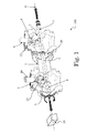
- the device 100 comprises a casing 1 which can be constituted by a single part, or as illustrated in figure 1 , it can comprise two or more parts mechanically connected to each other.
- the casing 1 contains at least a first fixed contact 2 and a second fixed contact 3 which are positioned spaced apart from each other and are suitable to be connected to two corresponding power connection terminals 4, 5 for realizing input/output connections into/out from the device 100 itself.
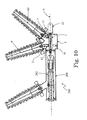
- first and second fixed contacts 2-3 by means of the respectively associated first power connection terminal 4 and second power connection terminal 5, can be electrically connected in input to and output from the device 100 with a phase of an electrical line, respectively, for instance using corresponding cables, or rods, or bars 6, 60 as schematically shown in the figures and in particular in figure 10 .
- first connection terminal 4 (and associated first fixed contact 2) can be connected in input from an electrical line and the second terminal 5 (and associated second fixed contact 3) can be connected in output towards a power or distribution transformer, respectively; however, other connections can be realized according to the various possible applications.
- first movable contact 12 and a second movable contact 13 which are spaced apart from each other and can be actuated simultaneously by suitable actuation means so as to electrically couple with the first fixed contact 2 and the second fixed contact 3, respectively.
- At least one of the first fixed contact 2 and the first movable contact 12 has a respective body shaped so as the first movable contact 12, when actuated, engages/couples with the first fixed contact 2 in at least a first coupling position (A) and in a second coupling position (B) which are spaced apart from each other; further, at least one of the second fixed contact 3 and the second movable contact 13 has a respective body shaped so as the second movable contact 13, when actuated together with the first movable 12 contact, engages/couples with said second fixed contact 3 in at least a third coupling position (C) and a fourth coupling position (D) which are spaced apart from each other.
- At least one of the first fixed contact 2 and first movable contact 12 has a respective body shaped so as the first movable contact 12, when actuated couples/engages with the first fixed contact 2 in at least a first coupling position (A) and in a second coupling position (B) which are angularly spaced from each other; at such coupling positions the first movable contact 12 is still and electrically coupled with the first fixed contact 2.
- At least one of the second fixed contact 3 and second movable contact 13 has a respective body shaped so as the second movable contact 13, when actuated together with the first movable contact 12, couples/engages with the second fixed contact 13 in at least a third coupling position (C) and a fourth coupling position (D) which are angularly spaced apart from each other; at such third and fourth coupling positions the second movable contact 13 is still and electrically coupled with the second fixed contact 3.
- one of the first or second couplings positions (A) (B) of the first fixed contact 2 with the first movable contact 12 is angularly substantially coincident with one of the third or fourth coupling positions (C) (D) of the second fixed contact 3 with the second movable contact 13.
- the first movable contact 12 and the first fixed contact 2 couple together in two predefined couplings positions (A) and (B) which are angularly spaced from each other, preferably of about 90°.
- the second movable contact 13 and the second fixed contact 3 couple together in two predefined couplings positions (C) and (D) which are angularly spaced from each other, preferably of about 90°.
- the coupling position (B) between the first fixed and movable contacts 2, 12 is angularly coincident with the coupling position (C) between the second fixed and movable contacts 3, 13.
- first movable contact 12 and the second movable contact 13 are mounted on and solidly move together with an actuation element 7.
- the actuation element 7 is placed inside the casing 1 rotating about a reference axis 8.
- the actuating element 7 rotates around the reference rotation axis 8 with the moving contacts 12 and 13 which rotate simultaneously to each other and solidly together with the actuation element 7; in turn, the first fixed contact 2 is positioned on the rotation path of the first movable contact 12 and the second fixed contact 3 is positioned on the rotation path of the second movable contact 13.
- the predefined first and second coupling positions (A) and (B) are angularly spaced from each other along the rotation path of the first movable contact 12, and the predefined third and fourth coupling positions (C) and (D) are angularly spaced from each other along the rotation path of the second movable contact 13.
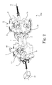
- the actuation element 7 can be constituted for example by a rod or shaft 7 which can be formed by one single piece, as for instance illustrated in figure 10 , or by two or more pieces connected together as for example illustrated in figures 1-2 .
- One end of the rotating actuation element 7 is operatively connected, e.g. by means of an insulating rod 9, to actuation means comprising for instance an electric motor 10 which is positioned outside the casing 1 and supplies the energy required to rotate the actuating element 7 and the contacts 12, 13 solidly connected therewith; the other end of the actuation element 7 can be connected to one side of the casing 1, e.g. by means of bearings, when the device 100 is used as a stand-alone component, or it can be connected operatively to other elements in case the switching device 100 is associated to or used in more complex switchgear devices.
- actuation means comprising for instance an electric motor 10 which is positioned outside the casing 1 and supplies the energy required to rotate the actuating element 7 and the contacts 12, 13 solidly connected therewith; the other end of the actuation element 7 can be connected to one side of the casing 1, e.g. by means of bearings, when the device 100 is used as a stand-alone component, or it can be connected operative
- the switching device 100 is a component of a hybrid switchgear 200 wherein the casing 1 is connected to a further casing 201 housing for example a circuit breaker 202.
- the end of the actuating element 7 is operatively connected to such a circuit breaker 202.
- the first movable contact 12 and the second movable contact 13 are mounted on the actuating element 7 substantially aligned to each other along the reference axis 8.
- the first movable contact 12 and the second movable contact 13 comprise a body having a U-shape or gripper-shape; the internal surfaces of the lateral facing sides 14 of the U-shaped or gripper-shaped body are provided with contact reeds or strips 15 suitable to electrically match with corresponding parts of the fixed contacts 2, 3 at the respective predefined coupling regions (A) or (B), and (C) or (D).
- the two movable contacts 12, 13, may not be identical to each other; however, according to the present disclosure, the two movable contacts 12 and 13 preferably are substantially identical to each other. In this way, manufacturing costs are optimized.
- the first fixed contact 2 comprises a body having a curved-blade shape extending for a certain angular sector, e.g. of about 90° or more; in particular, as shown in figure 4 , the external side surfaces of the curved-blade body of the first fixed contact 2 are silver-plated at least at the regions of its body defining and corresponding to the first and second coupling positions (A), (B).
- the entire surface from the coupling region (A) to the coupling region (B) is silver-plated on both sides, namely an arc of at least about 90° is covered, on the side surfaces, with silver plates; in this way, while moving, the first movable contact 12 touches a useful and continuous electrical contact surface of about 90° on the first fixed contact 2 between the two predefined coupling positions (A), (B), at which the first movable contact 12 stops and remains still and electrically connected to the first fixed contact 2.
- the second fixed contact 3 comprises a body having a curved-blade shape extending for a certain angular sector, e.g. of about 90° or more; as for the first fixed contact 2, also the external side surfaces of the curved-blade body of the second fixed contact 3 are silver-plated at least at the regions defining and corresponding to the third and fourth coupling positions (C), (D).
- the entire surface from the coupling region (C) to the coupling region (D) is silver-plated on both sides, namely an arc of at least about 90° is covered, on the side surfaces, with silver plates; hence, while moving, the second movable contact 13 touches a useful and continuous electrical contact surface of about 90° on the second fixed contact 3 between the two predefined coupling positions (A), (B), at which the second movable contact 13 stops and remains still and electrically connected to the second fixed contact 3.
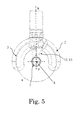
- the first and second fixed contacts 2, 3 are mounted inside the casing 1 opposite to each other with respect to said reference axis 8; more preferably, the first and second fixed contacts 2, 3 are substantially identical to each other so the embodiment illustrated to figure 4 can be applied to both fixed contacts 2, 3.
- the fixed contacts 2, 3 are mirror-positioned to each other with respect to a vertical plane X containing the rotation axis, as for example illustrated in figure 5 .
- the switching device 100 comprises, in addition to all elements previously described for the embodiment of figure 1 , a further fixed contact, namely, an earthing fixed contact 16 for connection to ground potential; in this way, the switching device 100 assumes the configuration of a combined disconnector-earthing switch device.
- the earthing contact 16 is placed inside the casing 1 along the rotation path of the first movable contact 12 and at a position such that the first movable contact 12 cannot simultaneously couple with the first fixed contact 2 and the earthing fixed contact 16.
- figure 6 schematically represents an operative condition where the first moving contact 12 is engaged with the first fixed contact 2 in the coupling position (A) and the second movable contact 13 is disconnected from the corresponding second fixed contact 3; in this condition, for instance the first bus bar 6 is electrically connected (in input or output) with the device 100 while the second bus bar 60 is disconnected.
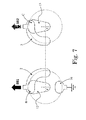
- the electric motor 10 actuates the actuation element 7 to rotate, e.g. of 90° degrees counterclockwise, the movable contacts 12, 13 rotate rigidly therewith and the first movable contact 12 stops and engages the first fixed contact 2 at the predefined second coupling position (B), while the second movable contact 13 stops and engages the second fixed contact 2 at the predefined third coupling position (C), as illustrated in figure 7 .
- both bus bars 6 and 60 are electrically connected (in input or output) with the switching device 100.
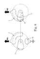
- the actuation element 7 e.g. of additional 90° degrees counterclockwise, the first movable contact 12 is disconnected from the first fixed contact 2, while the second movable contact 13 stops and engages with the second fixed contact 3 at the predetermined fourth coupling position (D), as shown in figure 8 .
- the first bus bar 6 is disconnected while the second bus bar 60 is electrically connected (in input or output) with the device 100.
- a further rotation of 90° counterclockwise of the actuation element 7 brings the first movable contact 12 to stop and engage the earthing fixed contact 16 which is at ground potential, while the second movable contact is disconnected from the second fixed contact 3, as illustrated in figure 9 .
- both bus bars 6 60 are disconnected and the device 100 is connected to ground potential.
- the switching device 100 according to the present disclosure offers some improvements over prior art solutions; indeed, thanks to the embodiments previously described, and in particular due to the configuration and mutual position of its various elements and especially the various contacts, the switching device 100 as a whole is more compact if compared to known devices of equivalent rate and performances. Indeed, in the switching device 100 according to the present disclosure each operative position is angularly spaced from the adjacent ones (following and preceding) of about 90°, thus allowing to decrease the diameter or maximum external size of the casing 1, while keeping the required dielectric clearances.
- the present disclosure also encompasses an electric substation or switchgear characterized in that it comprises a high voltage switching device 100 of the type previously described and as defined in the appended claims.
- the HV switching device 100 thus conceived is susceptible of modifications and variations, all of which are within the scope of the inventive concept as defined in particular by the appended claims; any possible combination of the previously disclosed embodiments/alternatives can be implemented and has to be considered within the inventive concept of the present disclosure; all the details may furthermore be replaced with technically equivalent elements.
- the casing 1 can be separated in two parts segregated from each other by means of an insulating disc 20 partially illustrated in figures 1 and 2 .
- the switching device 100 can be of the single-pole actuation type in which there are actuation means on each individual phase in order to perform the disconnection operation; as an alternative, the device can be of the three-pole actuation type, in which the energy for performing the disconnection operation on the three phases of the device is supplied by a single motor which is mechanically coupled to the disconnection units of each individual phase.
- the electric motor 10 can be replaced by any suitable drive or it is possible to use mechanical or hydraulic actuation means, or the terminals 4 and 5 can be realized integral with the associated fixed contacts 2, 3.
- Manual actuation means can also be provided as an alternative, or as an addition, to the above described actuation means.
- the silver plates suitable to couple with the reeds or strips 15 can be made of a different material or the reeds or strips 15 themselves can be differently shaped.
Landscapes
- Engineering & Computer Science (AREA)
- Power Engineering (AREA)
- Gas-Insulated Switchgears (AREA)
- Arc-Extinguishing Devices That Are Switches (AREA)
Priority Applications (3)
| Application Number | Priority Date | Filing Date | Title |
|---|---|---|---|
| EP13157477.4A EP2772928A1 (de) | 2013-03-01 | 2013-03-01 | Hochspannungsschaltvorrichtung |
| US14/190,410 US20140246298A1 (en) | 2013-03-01 | 2014-02-26 | High voltage switching device |
| CN201410074887.9A CN104021972A (zh) | 2013-03-01 | 2014-03-03 | 高压切换装置 |
Applications Claiming Priority (1)
| Application Number | Priority Date | Filing Date | Title |
|---|---|---|---|
| EP13157477.4A EP2772928A1 (de) | 2013-03-01 | 2013-03-01 | Hochspannungsschaltvorrichtung |
Publications (1)
| Publication Number | Publication Date |
|---|---|
| EP2772928A1 true EP2772928A1 (de) | 2014-09-03 |
Family
ID=47750576
Family Applications (1)
| Application Number | Title | Priority Date | Filing Date |
|---|---|---|---|
| EP13157477.4A Withdrawn EP2772928A1 (de) | 2013-03-01 | 2013-03-01 | Hochspannungsschaltvorrichtung |
Country Status (3)
| Country | Link |
|---|---|
| US (1) | US20140246298A1 (de) |
| EP (1) | EP2772928A1 (de) |
| CN (1) | CN104021972A (de) |
Cited By (2)
| Publication number | Priority date | Publication date | Assignee | Title |
|---|---|---|---|---|
| DE102016110252A1 (de) * | 2016-06-02 | 2017-12-07 | Schneider Electric Industries Sas | Schalteinrichtung |
| EP3579261A1 (de) * | 2018-06-08 | 2019-12-11 | ABB Schweiz AG | Hochspannungstrennschalter |
Families Citing this family (2)
| Publication number | Priority date | Publication date | Assignee | Title |
|---|---|---|---|---|
| US12243699B2 (en) * | 2021-05-12 | 2025-03-04 | Jeffrey Ross Gray | High voltage switch |
| EP4089704B1 (de) * | 2021-05-13 | 2025-04-09 | ABB Schweiz AG | Mittelspannungsschaltvorrichtung |
Citations (4)
| Publication number | Priority date | Publication date | Assignee | Title |
|---|---|---|---|---|
| BE650556A (fr) * | 1963-09-14 | 1965-01-15 | Recharge pour interrupteur-disjoncteur | |
| FR2628258A1 (fr) * | 1988-03-07 | 1989-09-08 | Merlin Gerin | Interrupteur rotatif multipolaire a enveloppe etanche commune a tous les poles |
| WO2000024100A1 (en) * | 1998-10-20 | 2000-04-27 | Abb Ricerca Spa | Gas-insulated switchgear device |
| FR2799895A1 (fr) * | 1999-10-15 | 2001-04-20 | Alstom | Commutateur electrique a enveloppe metallique compartimentee pour la mise en place de sectionneurs |
Family Cites Families (2)
| Publication number | Priority date | Publication date | Assignee | Title |
|---|---|---|---|---|
| IT1313321B1 (it) * | 1999-10-01 | 2002-07-17 | Abb Ricerca Spa | Apparecchiatura di interruzione e sezionamento isolata in gas. |
| JP4456521B2 (ja) * | 2005-04-28 | 2010-04-28 | 株式会社テーアンテー | 自動車用プッシュスイッチ |
-
2013
- 2013-03-01 EP EP13157477.4A patent/EP2772928A1/de not_active Withdrawn
-
2014
- 2014-02-26 US US14/190,410 patent/US20140246298A1/en not_active Abandoned
- 2014-03-03 CN CN201410074887.9A patent/CN104021972A/zh active Pending
Patent Citations (5)
| Publication number | Priority date | Publication date | Assignee | Title |
|---|---|---|---|---|
| BE650556A (fr) * | 1963-09-14 | 1965-01-15 | Recharge pour interrupteur-disjoncteur | |
| FR2628258A1 (fr) * | 1988-03-07 | 1989-09-08 | Merlin Gerin | Interrupteur rotatif multipolaire a enveloppe etanche commune a tous les poles |
| WO2000024100A1 (en) * | 1998-10-20 | 2000-04-27 | Abb Ricerca Spa | Gas-insulated switchgear device |
| EP1121738A1 (de) | 1998-10-20 | 2001-08-08 | ABB Ricerca SpA | Gasisolierte schaltvorrichtung |
| FR2799895A1 (fr) * | 1999-10-15 | 2001-04-20 | Alstom | Commutateur electrique a enveloppe metallique compartimentee pour la mise en place de sectionneurs |
Cited By (4)
| Publication number | Priority date | Publication date | Assignee | Title |
|---|---|---|---|---|
| DE102016110252A1 (de) * | 2016-06-02 | 2017-12-07 | Schneider Electric Industries Sas | Schalteinrichtung |
| EP3579261A1 (de) * | 2018-06-08 | 2019-12-11 | ABB Schweiz AG | Hochspannungstrennschalter |
| WO2019234110A1 (en) * | 2018-06-08 | 2019-12-12 | Abb Schweiz Ag | High voltage disconnector |
| US11515109B2 (en) | 2018-06-08 | 2022-11-29 | Hitachi Energy Switzerland Ag | High voltage disconnector |
Also Published As
| Publication number | Publication date |
|---|---|
| US20140246298A1 (en) | 2014-09-04 |
| CN104021972A (zh) | 2014-09-03 |
Similar Documents
| Publication | Publication Date | Title |
|---|---|---|
| US8264306B2 (en) | Movable contactor assembly for current limiting type molded case circuit breaker | |
| EP2979290B1 (de) | Messerschalter, schaltvorrichtung mit einem messerschalter und schaltanlage | |
| EP1218995B1 (de) | Gasisolierte schaltanlage | |
| EP2947733B1 (de) | Gasisolierte schaltanlage | |
| CN103608884B (zh) | 开关装置和开关柜 | |
| EP2772928A1 (de) | Hochspannungsschaltvorrichtung | |
| US9129768B2 (en) | Multipole electrical switching device | |
| US20120181156A1 (en) | Gas-insulated high-voltage switching system | |
| JP6990294B2 (ja) | ガス絶縁型開閉装置用の回路遮断器 | |
| US20080217153A1 (en) | Insulating Body For a Medium-Voltage Switchgear Assembly | |
| CN103368095A (zh) | 具有绝缘器的电气装置 | |
| TW561656B (en) | Metal enclosed type switch gear | |
| RU2410789C2 (ru) | Контактное устройство с ограничительным элементом, который ограничивает отклонение подвижной контакт-детали | |
| JP6990293B2 (ja) | ガス絶縁開閉装置用断路器極 | |
| CN102782791B (zh) | 断路器的驱动装置 | |
| JP5324530B2 (ja) | 高電圧開閉装置 | |
| CN106710974B (zh) | 低压断路器双故障触点执行机构 | |
| CN103000392B (zh) | 圆触头 | |
| JP5815449B2 (ja) | 真空遮断器 | |
| US20080105654A1 (en) | Polyphase Switching Device Comprising at Least Three Similar Interrupter Units | |
| EP1705767A1 (de) | Kombinierter Trenn-Erdungsschalter | |
| CN202601497U (zh) | 一种自动重合器 | |
| KR20130037931A (ko) | 가스 절연 개폐 장치의 접지 개폐기의 컨택트 | |
| EP1101262B1 (de) | Elektrische unterstation | |
| EP3776619B1 (de) | Flexibler leiter für trennschalter und trennschalter dafür |
Legal Events
| Date | Code | Title | Description |
|---|---|---|---|
| 17P | Request for examination filed |
Effective date: 20130301 |
|
| AK | Designated contracting states |
Kind code of ref document: A1 Designated state(s): AL AT BE BG CH CY CZ DE DK EE ES FI FR GB GR HR HU IE IS IT LI LT LU LV MC MK MT NL NO PL PT RO RS SE SI SK SM TR |
|
| AX | Request for extension of the european patent |
Extension state: BA ME |
|
| PUAI | Public reference made under article 153(3) epc to a published international application that has entered the european phase |
Free format text: ORIGINAL CODE: 0009012 |
|
| STAA | Information on the status of an ep patent application or granted ep patent |
Free format text: STATUS: THE APPLICATION IS DEEMED TO BE WITHDRAWN |
|
| 18D | Application deemed to be withdrawn |
Effective date: 20150304 |