EP2772998A2 - Elektrischer Anschlussdose - Google Patents
Elektrischer Anschlussdose Download PDFInfo
- Publication number
- EP2772998A2 EP2772998A2 EP14156952.5A EP14156952A EP2772998A2 EP 2772998 A2 EP2772998 A2 EP 2772998A2 EP 14156952 A EP14156952 A EP 14156952A EP 2772998 A2 EP2772998 A2 EP 2772998A2
- Authority
- EP
- European Patent Office
- Prior art keywords
- mounting portion
- vehicle body
- box body
- body panel
- water
- Prior art date
- Legal status (The legal status is an assumption and is not a legal conclusion. Google has not performed a legal analysis and makes no representation as to the accuracy of the status listed.)
- Withdrawn
Links
Images


Classifications
-
- H—ELECTRICITY
- H02—GENERATION; CONVERSION OR DISTRIBUTION OF ELECTRIC POWER
- H02G—INSTALLATION OF ELECTRIC CABLES OR LINES, OR OF COMBINED OPTICAL AND ELECTRIC CABLES OR LINES
- H02G3/00—Installations of electric cables or lines or protective tubing therefor in or on buildings, equivalent structures or vehicles
- H02G3/02—Details
- H02G3/08—Distribution boxes; Connection or junction boxes
- H02G3/088—Dustproof, splashproof, drip-proof, waterproof, or flameproof casings or inlets
Definitions
- the bracket to be provided for the electrical connection box is disposed at various positions of the box body according to the arrangement position of the electrical connection box within the vehicle body and the shape of the vehicle body panel.
- JP-A-2011-152846 discloses an electrical connection box with a bracket arranged above its box body.
- the water catch recess is formed in the base end of the bracket's mounting portion for mounting the box body onto the vehicle body panel, while the mounting portion is formed by such wall of the water catch recess as exists on the vehicle body panel side.
- the eaves portion is formed on the water discharge hole, the drop position of the water discharged from the water discharge hole can be kept away further from the box body. This can reduce a fear that the water dropping after discharged from the water discharge hole can flow to the box body.
- the reinforcing rib is formed in the water discharge hole forming portion, the water discharge hole can be formed without impairing the rigidity of the bracket.
- a clamp mounting portion is formed using the front wall of the water catch recess.
- a clamp for holding a wire harness is fixed by inserting it into the electrical connection box, vehicle body panel or the like. Therefore, a clamp mounting portion requires a depth dimension capable of inserting the insertion portion of the clamp therein. Thus, when the insertion depth of the insertion portion of the clamp is secured using the height of the wall of the water catch recess, the clamp mounting portion can be formed in the bracket with high space efficiency.
- a scattering prevention wall is formed in each of the two width-direction end edges of the eaves portion.
- the scattering prevention wall can prevent the water flowing on the eaves portion from being discharged in the width direction of the eaves portion. This enables the water discharged from the water discharge hole to flow to the projection end edge of the eaves portion positively, thereby being able to discharge the water to the vehicle body panel side positively.
- a pair of side walls connected to the rear wall are extended to the upper end edge of the mounting portion.
- the pair of side walls prevent the water from flowing outside the mounting portion, whereby the water can be guided to the water catch recess.
- the water reaching the bracket can be caught by the water catch recess more positively.
- the box body in the electrical connection box of any one of the first to fifth embodiments, includes on the vehicle body panel side surface thereof a short part mounting portion for mounting thereon a short part having a relatively small dimension of projection from the box body and a tall part mounting portion for mounting thereon a tall part having a relatively large dimension of projection from the box body, and the eaves portion, when the box body is mounted on the vehicle body panel, is disposed shifted at least from the vertically upward direction of the tall part mounting portion.
- the short and tall parts is used to represent various electric parts to be mounted on the box body, for example, a relay, a fuse and a connector.
- the water catch recess surrounded by walls in all directions.
- the water discharge hole is formed in such rear wall of the water catch recess as exists on the vehicle body panel side and thus water caught by the water catch recess is discharged toward the vehicle body panel opposite to the box body.
- the eaves portion is formed in the water discharge hole to retreat the discharge position of the water further toward the vehicle body panel from the box body, thereby being able to prevent water from flowing to the box body more effectively.
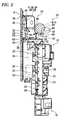
- the box body 12 has a substantially rectangular box shape. As shown in Fig. 1 , the box body 12 includes, on its surface 18 disposed on the vehicle body panel P side when it is mounted on the vehicle body, multiple small-size relay mounting portions 20 serving as short part mounting portions, large-size connector mounting portions 22 serving as tall part mounting portions 22, and multiple connector mounting portions 24. As shown in Fig. 2 , a small-size relay 26 serving as a short part is mounted on each small-size relay mounting portion 20, while a large-size relay 28 serving as a tall part is mounted on each large-size relay mounting portion 22.
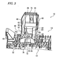
- the upper bracket 14 is formed separately from the box body 12 and is an integrally molded synthetic-resin member. As shown in Figs. 3 and 4 , the upper bracket 14 includes an upwardly extending mounting portion 36.
- the mounting portion 36 has an upper end disposed to project toward the vehicle body panel P, while a bolt insertion hole 38 is formed in the upper end of the mounting portion 36 to penetrate therethrough.
- the rear wall 42 includes a water discharge hole 50 which penetrates therethrough.
- the water discharge hole 50 is formed in the end of the rear wall 42 existing on the bottom surface 52 side of the water catch recess 40.
- the water catch recess 40 is opened, through the water discharge hole 50, in the surface 54 of the upper bracket 14 existing on the vehicle body panel P side.
- the water discharge hole 50 of this embodiment is formed to shift horizontally (in Fig. 1 , in the right and left direction) from the center of the water catch recess 40 and is situated shifted from the vertically upward direction (in Fig. 1 , the upward direction) of the large-size relay mounting portion 22 of the box body 12.
- the water discharge hole 50 includes, on the surface 54 side thereof, an eaves portion 56 projected from the surface 54 toward the vehicle body panel P. As shown in Fig. 2 , the eaves portion 56 continues with the bottom surface 52 of the water catch recess 40 and has a slope shape which is inclined downward as it projects from the surface 54 toward the vehicle body panel P. The projection end edge 58 of the eaves portion 56 on the vehicle body panel P side is projected toward the vehicle body panel P further than the box body 12 and is projected toward the vehicle body panel P further than the large-size relay 28 mounted on the large-size relay mounting portion 22 of the box body 12.
- the eaves portion 56 is formed at a position shifted from the vertically upward direction of the large-size relay mounting portion 22.
- the eaves portion 56 In the two end edges of the eaves portion 56 in the width direction (in Fig. 1 , in the right and left direction), there are formed a pair of scattering prevention walls 60 and 60.
- the scattering prevention walls 60 and 60 project upwardly of the eaves portion 56 and extend over the whole length of the eaves portion 56 in a direction where they project from the surface 54 of the eaves portion 56.
- the scattering prevention walls 60 and 60 also project downwardly of the eaves portion 56. Therefore, the eaves portion 56 has a section of a substantially H-like shape including the scattering prevention walls 60 and 60, whereby its strength is secured.
- the front wall 44 of the water catch recess 40 includes a clamp mounting portion 64.
- the front wall 44 may be projected inside the water catch recess 40 in a rectangular block shape.
- the front wall 44 has a rectangular-shaped storage space 66 which opens outside the upper bracket 14.
- the upper plate section 68 of the clamp mounting portion 64 has a clamp insertion hole 70 which penetrates therethrough.
- the upper end edge 72 of the front wall 44 is projected slightly upwardly of the upper plate section 68 to thereby prevent water having reached the upper plate section 68 from flowing out of the water catch recess 40.
- the reinforcing rib 62 is extended toward the front wall 44 and is connected to the clamp mounting portion 64.
- the water catch recess 40 is partitioned by the reinforcing rib 62 and clamp mounting portion 64 to be thereby divided into two divisional recesses 74a and 74b.
- the reinforcing rib 62 is disposed on the water discharge hole 50 and the divisional recesses 74a, 74b use the same water discharge hole 50, there is eliminated the need to penetratingly form separate water discharge holes in the respective divisional recesses 74a, 7b, thereby securing the strength of the upper bracket 14.
- the side walls 46, 48 of the water catch recess 40 are extended upwardly up to the upper end edge 76 of the mounting portion 36.
- the side walls 46, 48 are formed in the width-direction (in Fig. 1 , the right and left direction) two end edges of the mounting portion 36 over the whole length from the upper end edge 76 to the water catch recess 40.
- the thus structured upper bracket 14 is connected to the box body 12 by a slide lock 78 provided in the lower end portion thereof.
- the upper bracket 14 is disposed on the top of the box body 12 and the mounting portion 36 is projected upwardly of the box body 12.
- the lower bracket 16 is an integrally molded synthetic-resin member.
- the lower bracket 16 includes a bolt insertion hole 80 which penetrates therethrough.
- the lower bracket 16, substantially similarly to the upper bracket 14, is connected to the box body 12 by a slide lock 82 provided on the upper end thereof and is disposed on the bottom of the box body 12.
- the thus structured electrical connection box 12 is put on the vehicle room side of the vehicle body panel P, and then bolts (not shown) are inserted into the bolt insertion hole 38 of the mounting portion 36 of the upper bracket 14 and the bolt insertion hole 80 of the lower bracket 16 to be thereby threadedly engaged with the vehicle body panel P.
- the box body 12 is fixed to the vehicle body panel P through the upper bracket 14 and lower bracket 16.
- the upper bracket 14 exists vertically upward and the lower bracket 16 exists vertically downward, while the water catch recess 40 of the upper bracket 14 is open vertically upward.
- the insertion portion 86 of a clamp 84 holding a wire harness W/H is inserted through a clamp insertion hole 70 into the storage space 66 of the clamp mounting portion 64 of the upper bracket 14 and is engaged by the upper plate section 68. This enables the wire harness W/H to be fixed to the upper bracket 14.
- the electrical connection box 10 having a structure according to this embodiment, when water flows into the vehicle body due to rain, high-pressure cleaning or the like and flows on the vehicle body panel P, as shown by an arrow line in Fig. 2 , the water flowing on the vehicle body panel P firstly reaches the upper end edge 76 of the mounting portion 36 in contact with the vehicle body panel P.
- the water after reaching the mounting portion 36 flows downward along the mounting portion 36 without scattering round from the mounting portion 36 and is caught by the water catch recess 40.
- the water caught by the water catch recess 40 is discharged through the discharge hole 50 from the upper bracket 14 toward the vehicle body panel P.
- the water catch recess 40 since the water catch recess 40 catches the water having flowed to the upper bracket 14, the water can be prevented from flowing to the box body 12, whereby the box body 12 can be prevented from being touched by the water.
- the water discharge hole 50 and eaves portion 56 are arranged to face the vehicle body panel P. This enables water discharged from the water discharge hole 50 to flow to the vehicle body panel P, thereby being able to reduce a fear that water having dropped from the eaves portion 56 can scatter round in the air and thus touch the box body 12 again.
- the front wall 44 of the water catch recess 40 includes the clamp mounting portion 64.
- the clamp mounting portion 64 needs to secure the height dimension of the storage space 66 for storing the insertion portion 86 of the clamp 84.
- the clamp mounting portion 64 can be formed within the water catch recess 40 with high space efficiency.
- the reinforcing rib 62 is formed on the water discharge hole 50, the strength of the forming portion of the water discharge hole 50 in the upper bracket 14 is secured. Especially, since the reinforcing rib 62 is connected to the clamp mounting portion 64 to thereby connect the rear and front walls 42 and 44 to each other, the strength of the upper bracket 14 is secured at a higher level. In addition, while the reinforcing rib 62 is connected to the clamp mounting portion 64 to thereby divide the water catch recess 40 into the two divisional recesses 74a and 74b, provision of the reinforcing rib 62 on the water discharge hole 50 enables the two divisional recesses 74a and 74b to use one water discharge hole 50 in common. This eliminates the need for penetrating formation of water discharge holes respectively in the two divisional recesses 74a and 74b, thereby being able to secure the strength of the upper bracket 14.
- the invention is not limited to the specific description thereof.
- the number of mounting portions and water catch recesses to be formed in the bracket is not limitative but multiple mounting portions and water catch recesses may also be formed.
- means for mounting the mounting portions onto the vehicle body panel is naturally not limited to the means using bolts but, for example, there may be used means which is inserted into the vehicle body panel for fixation.
- the bracket may also be formed integrally with the box body.
- the clamp mounting portion may also be formed in any one of the wall portions of the water catch recess, for example, it may be formed in the side walls 46, 48 or rear wall 42 of the water catch recess 40.
- the clamp mounting portion is not always necessary.
- the reinforcing rib is not always necessary, either; and, the reinforcing rib may not be extended from the rear wall of the water catch recess to its opposed wall as in the above embodiment.
- the reinforcing rib 62 of the above embodiment may also be formed such that it is not extended to the clamp mounting portion 64 nor does it divide the water catch recess 40 into the two divisional recesses 74a, 74b.
- the electrical connection box 10 disclosed in the above embodiment is disposed on the vehicle room side of the vehicle body panel P which partitions the engine room and vehicle room from each other.
- the electrical connection box of the invention may also be provided outside the vehicle room, for example, within the engine room.
Landscapes
- Engineering & Computer Science (AREA)
- Architecture (AREA)
- Civil Engineering (AREA)
- Structural Engineering (AREA)
- Connection Or Junction Boxes (AREA)
Applications Claiming Priority (1)
| Application Number | Priority Date | Filing Date | Title |
|---|---|---|---|
| JP2013041244A JP5984717B2 (ja) | 2013-03-01 | 2013-03-01 | 電気接続箱 |
Publications (2)
| Publication Number | Publication Date |
|---|---|
| EP2772998A2 true EP2772998A2 (de) | 2014-09-03 |
| EP2772998A3 EP2772998A3 (de) | 2015-07-22 |
Family
ID=50159149
Family Applications (1)
| Application Number | Title | Priority Date | Filing Date |
|---|---|---|---|
| EP14156952.5A Withdrawn EP2772998A3 (de) | 2013-03-01 | 2014-02-27 | Elektrische Anschlussdose |
Country Status (4)
| Country | Link |
|---|---|
| EP (1) | EP2772998A3 (de) |
| JP (1) | JP5984717B2 (de) |
| CN (1) | CN104015675A (de) |
| IN (1) | IN2014DE00567A (de) |
Families Citing this family (4)
| Publication number | Priority date | Publication date | Assignee | Title |
|---|---|---|---|---|
| JP6144297B2 (ja) * | 2015-04-27 | 2017-06-07 | 矢崎総業株式会社 | 電気接続箱及びワイヤハーネス |
| JP6440124B2 (ja) * | 2015-07-16 | 2018-12-19 | 住友電装株式会社 | 電気接続箱用ブラケットおよびそれを用いたブラケット付電気接続箱 |
| JP7384759B2 (ja) * | 2020-07-13 | 2023-11-21 | 住友電装株式会社 | 電気接続箱 |
| WO2024250034A1 (en) * | 2023-06-02 | 2024-12-05 | Easy Solar Products, Inc. | Improved outdoor electrical gutter |
Citations (1)
| Publication number | Priority date | Publication date | Assignee | Title |
|---|---|---|---|---|
| JP2011152846A (ja) | 2010-01-27 | 2011-08-11 | Suzuki Motor Corp | 電装部品の被水防止構造 |
Family Cites Families (6)
| Publication number | Priority date | Publication date | Assignee | Title |
|---|---|---|---|---|
| JPH07143647A (ja) * | 1993-11-19 | 1995-06-02 | Sumitomo Wiring Syst Ltd | ワイヤハーネス用成形プロテクタのクランプ構造 |
| JP3311656B2 (ja) * | 1997-10-01 | 2002-08-05 | 矢崎総業株式会社 | 電気接続用組立体の固定構造 |
| JP2000013957A (ja) * | 1998-06-23 | 2000-01-14 | Sumitomo Wiring Syst Ltd | 自動車用の電気接続箱 |
| JP4265990B2 (ja) * | 2004-04-12 | 2009-05-20 | 株式会社オートネットワーク技術研究所 | 電気接続箱 |
| JP4901374B2 (ja) * | 2006-08-31 | 2012-03-21 | 矢崎総業株式会社 | 電気接続箱の排水構造 |
| JP5187245B2 (ja) * | 2009-03-16 | 2013-04-24 | 住友電装株式会社 | 電気接続箱 |
-
2013
- 2013-03-01 JP JP2013041244A patent/JP5984717B2/ja not_active Expired - Fee Related
-
2014
- 2014-02-27 EP EP14156952.5A patent/EP2772998A3/de not_active Withdrawn
- 2014-02-28 CN CN201410073395.8A patent/CN104015675A/zh active Pending
- 2014-02-28 IN IN567DE2014 patent/IN2014DE00567A/en unknown
Patent Citations (1)
| Publication number | Priority date | Publication date | Assignee | Title |
|---|---|---|---|---|
| JP2011152846A (ja) | 2010-01-27 | 2011-08-11 | Suzuki Motor Corp | 電装部品の被水防止構造 |
Also Published As
| Publication number | Publication date |
|---|---|
| JP2014171302A (ja) | 2014-09-18 |
| EP2772998A3 (de) | 2015-07-22 |
| JP5984717B2 (ja) | 2016-09-06 |
| IN2014DE00567A (de) | 2015-06-19 |
| CN104015675A (zh) | 2014-09-03 |
Similar Documents
| Publication | Publication Date | Title |
|---|---|---|
| JP6764536B2 (ja) | 車両のピラー構造体 | |
| EP2882055B1 (de) | Elektrofahrzeugladegerät | |
| EP2772998A2 (de) | Elektrischer Anschlussdose | |
| KR101923844B1 (ko) | 전선 수용 프로텍터 | |
| US20130265728A1 (en) | Electronic control unit | |
| JP5935752B2 (ja) | 電気接続箱 | |
| US20170086318A1 (en) | Electronic apparatus | |
| US10122159B2 (en) | Electric connection box | |
| JP5614998B2 (ja) | 車両用電子機器 | |
| US11679815B2 (en) | Liquid discharge structure | |
| JP6349160B2 (ja) | 電気接続箱 | |
| JP2015074333A (ja) | ボックス | |
| JP6047130B2 (ja) | 電気接続箱 | |
| CN209165707U (zh) | 走线结构及空调器 | |
| US9509128B2 (en) | Electrical junction box | |
| JP2001186627A (ja) | 電気接続箱の水抜き構造 | |
| KR200487874Y1 (ko) | 부품장착장치 | |
| CN113394594B (zh) | 防滴结构、带有防滴结构的连接器及电连接盒 | |
| JP7158290B2 (ja) | ブラケット | |
| CN104659722B (zh) | 电气接线箱 | |
| KR102123952B1 (ko) | 박스용 부품 장착장치 | |
| CN104682292B (zh) | 电气接线箱 | |
| JP2021118033A (ja) | コネクタ防滴部材及びワイヤハーネス | |
| BR112019027450B1 (pt) | Estrutura de pilar do veículo | |
| JP2016039753A (ja) | 車両搭載用筐体 |
Legal Events
| Date | Code | Title | Description |
|---|---|---|---|
| PUAI | Public reference made under article 153(3) epc to a published international application that has entered the european phase |
Free format text: ORIGINAL CODE: 0009012 |
|
| 17P | Request for examination filed |
Effective date: 20140227 |
|
| AK | Designated contracting states |
Kind code of ref document: A2 Designated state(s): AL AT BE BG CH CY CZ DE DK EE ES FI FR GB GR HR HU IE IS IT LI LT LU LV MC MK MT NL NO PL PT RO RS SE SI SK SM TR |
|
| AX | Request for extension of the european patent |
Extension state: BA ME |
|
| PUAL | Search report despatched |
Free format text: ORIGINAL CODE: 0009013 |
|
| AK | Designated contracting states |
Kind code of ref document: A3 Designated state(s): AL AT BE BG CH CY CZ DE DK EE ES FI FR GB GR HR HU IE IS IT LI LT LU LV MC MK MT NL NO PL PT RO RS SE SI SK SM TR |
|
| AX | Request for extension of the european patent |
Extension state: BA ME |
|
| RIC1 | Information provided on ipc code assigned before grant |
Ipc: H02G 3/08 20060101AFI20150615BHEP |
|
| R17P | Request for examination filed (corrected) |
Effective date: 20160120 |
|
| RBV | Designated contracting states (corrected) |
Designated state(s): AL AT BE BG CH CY CZ DE DK EE ES FI FR GB GR HR HU IE IS IT LI LT LU LV MC MK MT NL NO PL PT RO RS SE SI SK SM TR |
|
| GRAP | Despatch of communication of intention to grant a patent |
Free format text: ORIGINAL CODE: EPIDOSNIGR1 |
|
| STAA | Information on the status of an ep patent application or granted ep patent |
Free format text: STATUS: GRANT OF PATENT IS INTENDED |
|
| INTG | Intention to grant announced |
Effective date: 20171211 |
|
| STAA | Information on the status of an ep patent application or granted ep patent |
Free format text: STATUS: THE APPLICATION IS DEEMED TO BE WITHDRAWN |
|
| 18D | Application deemed to be withdrawn |
Effective date: 20180424 |