EP2773063B1 - Procédé d'alimentation électrique, module de partage de courant et système d'alimentation électrique - Google Patents
Procédé d'alimentation électrique, module de partage de courant et système d'alimentation électrique Download PDFInfo
- Publication number
- EP2773063B1 EP2773063B1 EP11877428.0A EP11877428A EP2773063B1 EP 2773063 B1 EP2773063 B1 EP 2773063B1 EP 11877428 A EP11877428 A EP 11877428A EP 2773063 B1 EP2773063 B1 EP 2773063B1
- Authority
- EP
- European Patent Office
- Prior art keywords
- currents
- power supply
- current
- equalization module
- current equalization
- Prior art date
- Legal status (The legal status is an assumption and is not a legal conclusion. Google has not performed a legal analysis and makes no representation as to the accuracy of the status listed.)
- Active
Links
- 238000000034 method Methods 0.000 title claims description 16
- 238000001514 detection method Methods 0.000 claims description 17
- 238000012358 sourcing Methods 0.000 claims description 12
- 238000000899 pressurised-fluid extraction Methods 0.000 description 12
- 238000010586 diagram Methods 0.000 description 9
- 230000005611 electricity Effects 0.000 description 2
- 230000005540 biological transmission Effects 0.000 description 1
- 238000005516 engineering process Methods 0.000 description 1
- 238000012986 modification Methods 0.000 description 1
- 230000004048 modification Effects 0.000 description 1
- 230000003287 optical effect Effects 0.000 description 1
Images

Classifications
-
- H—ELECTRICITY
- H04—ELECTRIC COMMUNICATION TECHNIQUE
- H04L—TRANSMISSION OF DIGITAL INFORMATION, e.g. TELEGRAPHIC COMMUNICATION
- H04L12/00—Data switching networks
- H04L12/02—Details
- H04L12/10—Current supply arrangements
-
- H—ELECTRICITY
- H04—ELECTRIC COMMUNICATION TECHNIQUE
- H04L—TRANSMISSION OF DIGITAL INFORMATION, e.g. TELEGRAPHIC COMMUNICATION
- H04L12/00—Data switching networks
- H04L12/28—Data switching networks characterised by path configuration, e.g. LAN [Local Area Networks] or WAN [Wide Area Networks]
- H04L12/40—Bus networks
- H04L12/40006—Architecture of a communication node
- H04L12/40045—Details regarding the feeding of energy to the node from the bus
Definitions
- Embodiments of the present invention relate to the field of communications technologies, and in particular, to a power supply method, a current equalization module, and a power supply system.
- PoE Power Over Ethernet
- PSE Power Sourcing Equipment
- PD powered Device
- the prior art provides a method of supplying electric energy with large power, in which two or more PSEs are used for power supply. Electric energy generated by these PSEs is transmitted to a PD across the Ethernet, separately passes through a direct current/direct current (Direct Current/Direct Current, DC/DC for short) voltage converter, and is then output to the load after being combined by using a current equalization module. In this way, the power available for a load is twice of that when only a PSE and a PD are deployed. When a load needs larger power, more PSEs, PDs, and DC/DCs need to be connected in parallel before the currents are equalized.
- DC/DC direct current/direct current
- the present invention provides a power supply method, a current equalization module, and a power supply system, which helps reduce the number of required voltage converters (that is, DC/DC modules) and thereby reduces the implementation costs.
- the present invention provides a power supply method, comprising: detecting, by a current equalization module, currents of at least two power supply lines to which the current equalization module is connected; equalizing, by the current equalization module, the currents of the at least two power supply lines based on the intensity of the currents that have been detected in order to enable the currents of at least two power supply lines to have the same intensity; and sending, by the current equalization module, the equalized currents to a voltage converter, so that the voltage converter supplies power to a terminal device after converting voltage corresponding to the equalized currents, characterised in that the step of detecting, by a current equalization module, currents of at least two power supply lines to which the current equalization module is connected comprises: detecting, by the current equalization module after the current equalization module has detected that
- the present invention provides a current equalization module, comprising a current detection unit, a central control unit, and a current control unit, wherein: the current detection unit is configured to detect currents of at least two power supply lines to which the current equalization module is connected; the central control unit is configured to send a current equalization signal to the current control unit based on the intensity of the currents that have been detected by the current detection unit; and the current control unit is configured to equalize the currents of the at least two power supply lines based on the current equalization signal sent by the central control unit to enable the currents of at least two power supply lines to have the same intensity, and then send the equalized currents to a voltage converter, characterised by further comprising: a power-on control unit, configured to instruct, after the current equalization module has detected that powered devices connected to each of the at least two power supply lines has been powered on, the current detection unit to detect the currents of the at least two power supply lines to which the current equalization module is connected.
- a power-on control unit configured to instruct, after
- the present invention provides a power supply system, comprising at least two pieces of power sourcing equipment, at least two powered device, a current equalization module, and a voltage converter, wherein: the at least two pieces of power sourcing equipment are configured to output currents; the at least two powered devices are configured to receive currents from the at least two power sourcing equipments connected to the at least two powered devices, separately, and send the currents to the current equalization module, wherein the at least two powered devices are connected to the current equalizer module by using at least two power supply lines; the current equalization module is configured to detect currents of at least two power supply lines to which the current equalization module is connected, equalize the currents of the at least two power supply lines based on the intensity of the currents that have been detected to enable the currents of at least two power supply lines to have the same intensity, and send the equalized currents to the voltage converter; and the voltage converter is configured to convert voltage corresponding to the equalized currents and supply power to a terminal device, and characterised in that the current equalization
- a current equalization module equalizes the currents of at least two power supply lines to which the current equalization module is connected, and a voltage converter converts the voltage of the currents before supplying power to terminal devices.
- a voltage converter that is, a DC/DC module
- currents have been equalized before arriving at a voltage converter (that is, a DC/DC module), so that only one voltage converter (that is, one DC/DC module) is used even in the case of large power output, which reduces the number of required voltage converters (that is, DC/DC modules) and thereby reduces the costs.
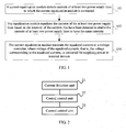
- FIG. 1 is a flow chart of a power supply method according to an embodiment of the present invention. As shown in FIG. 1 , the power supply method includes the following steps:
- the current equalization module detects the currents of the at least two power supply lines to which the current equalization module is connected.
- a current equalization module equalizes the currents of at least two power supply lines to which the current equalization module is connected, and a voltage converter converts the voltage of the currents, and then the voltage converter supplies power to terminal devices.
- a voltage converter that is, a DC/DC module
- currents have been equalized before arriving at a voltage converter (that is, a DC/DC module), so that only one voltage converter (that is, one DC/DC module) is used even in the case of large power output, which reduces the number of required voltage converters (that is, DC/DC modules) and thereby reduces the costs.
- the program may be stored in a computer readable storage medium. When the program is run, the foregoing steps of the methods in the embodiments are performed.
- the storage medium may be any medium capable of storing program codes, such as ROM, RAM, magnetic disk, or optical disk.
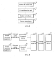
- FIG. 2 is a schematic structural diagram of a current equalization module according to an embodiment of the present invention.
- the current equalization module in this embodiment helps realize the power supply method according to the embodiment shown in FIG. 1 .
- the current equalization module may include a current detection unit 21, a central control unit 22, and a current control unit 23.
- the current detection unit 21 is configured to detect currents in at least two power supply lines to which the current equalization module is connected.
- the central control unit 22 is configured to send a current equalization signal to the current control unit 23 based on the intensity of the currents that have been detected by the current detection unit 21.
- the current control unit 23 is configured to equalize the currents of the at least two power supply lines based on the current equalization signal sent by the central control unit 22 to enable the currents of at least two power supply lines to have the same intensity, and then send the equalized currents to a voltage converter.
- the current equalization module equalizes the currents of at least two power supply lines to which the current equalization module is connected, and a voltage converter converts the voltage of the currents before supplying power to terminal devices.
- a voltage converter that is, a DC/DC module
- currents have been equalized before arriving at a voltage converter (that is, a DC/DC module), so that only one voltage converter (that is, one DC/DC module) is used even in the case of large power output, which reduces the number of required voltage converters (that is, DC/DC modules) and thereby reduces the costs.
- FIG. 3 is a schematic structural diagram of a current equalization module according to another embodiment of the present invention. Compared with the current equalization module shown in FIG. 2 , the current equalization module shown in FIG. 3 further includes:
- the current equalization module equalizes the currents of at least two power supply lines to which the current equalization module is connected, and a voltage converter converts the voltage of the currents before supplying power to terminal devices.
- a voltage converter that is, a DC/DC module
- currents have been equalized before arriving at a voltage converter (that is, a DC/DC module), so that only one voltage converter (that is, one DC/DC module) is used even in the case of large power output, which reduces the number of required voltage converters (that is, DC/DC modules) and thereby reduces the costs.
- FIG. 4 is a schematic structural diagram of a power supply system according to an embodiment of the present invention.
- the power supply system may include at least two power sourcing equipments 41, at least two powered devices 42, a current equalization module 43, and a voltage converter 44.
- the at least two power sourcing equipments 41 are configured to output currents.
- the at least two powered devices 42 are configured to receive currents of the at least two power sourcing equipments 41 to which they are connected, separately, and send the currents to the current equalization module 43. There should be at least two power supply lines between the at least two powered devices 42 and the current equalization module 43.
- the current equalization module 43 is configured to detect currents of at least two power supply lines connected to itself, equalize the currents of the at least two power supply lines based on the intensity of the currents that have been detected in order to enable the currents of at least two power supply lines to have the same intensity, and send the equalized currents to a voltage converter 44. Specifically, the current equalization module 43 can detect currents of the at least two power supply lines after detecting that the powered devices 42 connected to the at least two power supply lines have been powered on. That is, according to this embodiment, power is supplied to terminal devices only after the powered devices 42 connected to the at least two power supply lines are powered on. In this way, the damage to terminal devices and other safety incidents are prevented, which are caused by an excessively large current flowing through one power supply line due to different time when the at least two power supply lines transmit electricity.
- the current equalization module 43 can be designed according to the embodiment illustrated in FIG. 2 or FIG. 3 .
- the voltage converter 44 is configured to convert the voltage of the equalized currents and supply power to a terminal device 45.
- the at least two power sourcing equipments 41 may be integrated on the same device or arranged on multiple devices in a distributed manner, and the at least two powered devices 42 may be arranged likewise.
- the voltage converter 44 converts the voltage of the currents, and then voltage converter supplies power to the terminal device 45.
- currents have been equalized before arriving at the voltage converter 44 (that is, the DC/DC module), so that only one voltage converter (that is, one DC/DC module) is used even in the case of large power output, which reduces the number of required voltage converters 44 (that is, DC/DC modules) and thereby reduces the costs.
- FIG. 5 is a schematic structural diagram of a power supply system according to another embodiment of the present invention, in which a DC/DC module which is used as the voltage converter is used as an example for description.
- the power supply system may include a PSE 51, a PD 52, a DC/DC module 54, a terminal device 55, and a current equalization module 53.
- the power supply system includes two PSEs 51, two PDs 52, one current equalization module 53, one DC/DC module 54, and one terminal device 55. That is, the embodiment takes the power supply system with two PDs as an example and is not limited hereto.
- the implementation scheme of the power supply system including at least three PDs is similar to that of a power supply system with two PDs, which is not further described herein.
- the two PSEs 51 may be integrated on the same device or arranged on multiple devices in a distributed manner; likewise, the two PDs 52 may be integrated on the same device or arranged on multiple devices in a distributed manner.
- the current equalization module 53 includes a power-on control unit 531, a current control unit 532, a current detection unit 533, and a central control unit 534.
- a PSE 51 outputs a current
- a PD 52 receives the current output by the PSE 51 to which the PD 52 is connected.
- the power-on control unit 531 of the current equalization module is configured to instruct, after the current equalization module has detected that two PDs 52 have been powered on, the current detection unit 533 to detect a current of the power supply line that connects to the current equalization module 53. That is, the power-on control unit 531 implements a process in which a circuit is on and succeeding circuits and terminal devices are supplied with power only after all PDs 52 of the power supply system have been powered on. In this way, the damage to terminal devices or other safety incidents are prevented, which are caused by an excessively large current flowing through one power supply line due to different time when the at least two power supply lines transmit electricity.
- the current detection unit 533 is configured to detect the current of the power supply line that connects to the current equalization module 53. As shown in FIG. 5 , the current detection unit 533 detects the current of the 48 V-power supply line that connects to the current equalization module 53 and then sends a current signal that has been detected or a voltage signal converted from the current signal that has been detected to the central control unit 534. Alternatively, the current detection unit 533 may send the intensity of the currents that have been detected to the central control unit 534 in other ways, which is not limited in this embodiment.
- the central control unit 534 sends a current equalization signal to the current control unit 532 based on the intensity of the currents that have been detected, instructing the current control unit 532 to equalize the currents of two PoE-lines to which the current equalization module is connected, so that the currents of the two PoE-lines can be equal in intensity. That is, after receiving the current equalization signal from the central control unit 534, the current control unit 532 equalizes the currents of the two PoE-lines to which the current equalization module 53 is connected in order to enable the currents of two PoE-lines to have the same intensity.
- the DC/DC module 54 supplies power to the terminal device 55 after converting voltage corresponding to the equalized currents.
- the DC/DC module 54 converts the voltage of the equalized currents and then supplies power to the terminal device 55. In this way, currents have been equalized before arriving at the DC/DC module 54, so that only one DC/DC module 54 is used even in the case of large power output, which reduces the number of required DC/DC modules 54 and thereby reduces the costs.
- the power supply method, current equalization module, and power supply system provided by embodiments of the present invention can be applied to not only PoE but also such related scenarios as where strict control is exerted on a current of a single power cable.
- modules in the apparatuses provided in the embodiments may be arranged in the apparatuses in a distributed manner according to the description of the embodiments, or may be arranged in one or multiple apparatuses which are different from those described in the embodiments.
- the modules in the foregoing embodiments may be combined into one module, or split into a plurality of sub-modules.
Landscapes
- Engineering & Computer Science (AREA)
- Computer Networks & Wireless Communication (AREA)
- Signal Processing (AREA)
- Direct Current Feeding And Distribution (AREA)
- Electric Propulsion And Braking For Vehicles (AREA)
Claims (3)
- Procédé d'alimentation électrique comprenant :la détection, grâce à un module d'égalisation de courants, de courants d'au moins deux lignes d'alimentation auxquelles est relié le module d'égalisation de courants, l'égalisation, grâce au module d'égalisation de courants, des courants des deux lignes d'alimentation ou plus sur la base de l'intensité des courants qui ont été détectés afin de permettre l'obtention d'une même intensité pour les courants des deux lignes d'alimentation ou plus, etl'envoi, grâce au module d'égalisation de courants, des courants égalisés vers un convertisseur de tension de telle sorte que le convertisseur de tension fournisse de l'énergie à un terminal après avoir converti la tension correspondant aux courants égalisés, caractérisé en ce quel'étape de détection, grâce à un module d'égalisation de courants, de courants d'au moins deux lignes d'alimentation auxquelles est relié le module d'égalisation de courants comprend :la détection des courants des deux lignes d'alimentation ou plus reliées au module d'égalisation de courants, grâce au module d'égalisation de courants après que le module d'égalisation de courants a détecté que des dispositifs alimentés, reliés à chacune des deux lignes d'alimentation ou plus, ont été mis sous tension.
- Module d'égalisation de courants, comprenant une unité de détection de courant (21) une unité de contrôle centrale (22) et une unité de régulation de courant (23), dans lequel :l'unité de détection de courant est configurée pour détecter des courants d'au moins deux lignes d'alimentation auxquelles est relié le module d'égalisation de courants,l'unité de contrôle centrale est configurée pour envoyer un signal d'égalisation de courants à l'unité de régulation de courant sur la base de l'intensité des courants qui ont été détectés par l'unité de détection de courant, etl'unité de régulation de courant est configurée pour égaliser les courants des deux lignes d'alimentation ou plus sur la base du signal d'égalisation de courants envoyé par l'unité de contrôle centrale afin de permettre l'obtention d'une même intensité pour les courants des deux lignes d'alimentation ou plus, et ensuite pour envoyer les courants égalisés vers un convertisseur de tension, caractérisé en ce qu'il comprend en outre :une unité de contrôle de mise sous tension (24) configurée pour ordonner à l'unité de détection de courant de détecter les courants des deux lignes d'alimentation ou plus auxquelles est relié le module d'égalisation de courants, après que le module d'égalisation de courants a détecté que des dispositifs alimentés reliés à chacune des deux lignes d'alimentation ou plus ont été mis sous tension.
- Système d'alimentation, comprenant au moins deux équipements formant source de puissance (41), au moins deux dispositifs alimentés (42), un module d'égalisation de courants (43) et un convertisseur de tension (44), dans lequel :les deux équipements formant source de puissance ou plus sont configurés pour fournir des courants en sortie,les deux dispositifs alimentés ou plus sont configurés pour recevoir des courants provenant des deux équipements formant source de puissance ou plus reliés séparément aux deux dispositifs alimentés ou plus, et pour envoyer les courants vers le module d'égalisation de courants, dans lequel les deux dispositifs alimentés ou plus sont reliés au module d'égalisation de courants en utilisant au moins deux lignes d'alimentation,le module d'égalisation de courants est configuré pour détecter des courants d'au moins deux lignes d'alimentation auxquelles est relié le module d'égalisation de courants, pour égaliser les courants des deux lignes d'alimentation ou plus sur la base de l'intensité des courants qui ont été détectés afin de permettre aux courants d'au moins deux lignes d'alimentation de présenter la même intensité, et pour envoyer les courants égalisés vers le convertisseur de tension, etle convertisseur de tension est configuré pour convertir une tension correspondant aux courants égalisés et fournir une alimentation à un terminal, et caractérisé en ce quele module d'égalisation de courants est en particulier configuré pour détecter les courants des deux lignes d'alimentation ou plus auxquelles est relié le module d'égalisation de courants, après que le module d'égalisation de courants a détecté que des dispositifs alimentés reliés à chacune des deux lignes d'alimentation ou plus ont été mis sous tension.
Applications Claiming Priority (1)
| Application Number | Priority Date | Filing Date | Title |
|---|---|---|---|
| PCT/CN2011/084062 WO2013086720A1 (fr) | 2011-12-15 | 2011-12-15 | Procédé d'alimentation électrique, module de partage de courant et système d'alimentation électrique |
Publications (3)
| Publication Number | Publication Date |
|---|---|
| EP2773063A4 EP2773063A4 (fr) | 2014-09-03 |
| EP2773063A1 EP2773063A1 (fr) | 2014-09-03 |
| EP2773063B1 true EP2773063B1 (fr) | 2015-12-09 |
Family
ID=48611825
Family Applications (1)
| Application Number | Title | Priority Date | Filing Date |
|---|---|---|---|
| EP11877428.0A Active EP2773063B1 (fr) | 2011-12-15 | 2011-12-15 | Procédé d'alimentation électrique, module de partage de courant et système d'alimentation électrique |
Country Status (3)
| Country | Link |
|---|---|
| EP (1) | EP2773063B1 (fr) |
| CN (1) | CN103688487A (fr) |
| WO (1) | WO2013086720A1 (fr) |
Families Citing this family (7)
| Publication number | Priority date | Publication date | Assignee | Title |
|---|---|---|---|---|
| WO2015124215A1 (fr) * | 2014-02-24 | 2015-08-27 | Telefonaktiebolaget L M Ericsson (Publ) | Commande d'une alimentation électrique à plusieurs canaux |
| CN105281315A (zh) | 2014-07-24 | 2016-01-27 | 中兴通讯股份有限公司 | 一种通信网的供电控制装置和方法 |
| CN105786070B (zh) * | 2014-12-23 | 2019-07-02 | 中兴通讯股份有限公司 | 通信网供电的控制装置和方法 |
| CN107844185B (zh) * | 2016-09-19 | 2020-01-31 | 华为数字技术(成都)有限公司 | 一种电源管理方法及装置 |
| CN109005041B (zh) * | 2017-06-07 | 2022-05-13 | 中兴通讯股份有限公司 | 一种局端设备、反向供电系统和方法 |
| TWI777077B (zh) * | 2019-07-31 | 2022-09-11 | 神準科技股份有限公司 | 網路供電均流系統及方法 |
| CN111884820B (zh) * | 2020-07-23 | 2021-12-07 | 威创集团股份有限公司 | 一种以太网双网口和直流冗余供电系统 |
Family Cites Families (8)
| Publication number | Priority date | Publication date | Assignee | Title |
|---|---|---|---|---|
| US7299368B2 (en) * | 2003-10-16 | 2007-11-20 | Microsemi Corp.-Analog Mixed Signal Group Ltd. | High power architecture for power over Ethernet |
| CN101112042B (zh) * | 2005-01-25 | 2012-01-04 | 凌特公司 | 区分网络接口卡和以太网供电系统短路状态的系统和方法 |
| US7490251B2 (en) * | 2006-04-13 | 2009-02-10 | Cisco Technology, Inc. | Method and apparatus for current sharing ethernet power across four conductor pairs using a midspan device |
| CN101594236B (zh) * | 2009-06-29 | 2012-09-05 | 华为技术有限公司 | 一种以太网供电poe的实现方法、装置及系统 |
| US8935543B2 (en) * | 2010-04-02 | 2015-01-13 | Andrew Llc | Method and apparatus for distributing power over communication cabling |
| CN101977115B (zh) * | 2010-09-07 | 2014-01-01 | 中兴通讯股份有限公司 | 一种实现以太网供电控制的方法和装置 |
| CN201957037U (zh) * | 2010-12-10 | 2011-08-31 | 上海市共进通信技术有限公司 | 以太网供电系统中的受电端设备测试装置 |
| CN102215113B (zh) * | 2011-06-08 | 2013-12-25 | 北京星网锐捷网络技术有限公司 | 以太网供电方法、装置及网络设备 |
-
2011
- 2011-12-15 EP EP11877428.0A patent/EP2773063B1/fr active Active
- 2011-12-15 WO PCT/CN2011/084062 patent/WO2013086720A1/fr not_active Ceased
- 2011-12-15 CN CN201180071987.0A patent/CN103688487A/zh active Pending
Also Published As
| Publication number | Publication date |
|---|---|
| EP2773063A4 (fr) | 2014-09-03 |
| WO2013086720A1 (fr) | 2013-06-20 |
| EP2773063A1 (fr) | 2014-09-03 |
| CN103688487A (zh) | 2014-03-26 |
Similar Documents
| Publication | Publication Date | Title |
|---|---|---|
| EP2773063B1 (fr) | Procédé d'alimentation électrique, module de partage de courant et système d'alimentation électrique | |
| US11843246B2 (en) | Safety power disconnection for power distribution over power conductors to power consuming devices | |
| EP2587718B1 (fr) | Dispositif de commutation un paire de conducteurs dans un système "Power over Ethernet" | |
| US20100153751A1 (en) | Network equipment | |
| US10158228B2 (en) | Power supply device, method of supplying power, and power supply system | |
| JP5457505B2 (ja) | 並列通信装置及びその通信方法 | |
| EP3174172A1 (fr) | Dispositif de commande d'alimentation et procédé pour un réseau de communication | |
| CN102801535B (zh) | 以太网供电传输系统 | |
| EP3495913B1 (fr) | Contrôle d'alimentation électrique pour un réseau de communication | |
| US10112558B2 (en) | System, method and apparatus for one-pair power over ethernet in an automotive application | |
| US10461555B2 (en) | Battery charging for mobile devices | |
| US10333723B2 (en) | Control device and method for power supplying of communications network | |
| JP4685896B2 (ja) | 受給電アダプタ | |
| KR101510046B1 (ko) | 전력 모니터링과 관리를 하는 장치 및 이를 이용한 센서 신호 처리 방법 | |
| EP3386148B1 (fr) | Procédé de commande d'alimentation électrique et appareil pour un réseau de communication | |
| WO2019039234A1 (fr) | Terminal de réception d'énergie, système de communication et procédé de fourniture d'énergie | |
| JP2013148943A (ja) | 電力供給システム、給電側機器及び受電側機器 | |
| JP2012080736A (ja) | 分散直流電源制御回路 | |
| CN103840957A (zh) | 链路功耗控制方法和控制器 | |
| US10148446B2 (en) | Electronic device and method for supplying power over ethernet | |
| KR101387981B1 (ko) | PoE(Power over Ethernet)를 이용하여 전력을 제공하기 위한 방법, 장치, 시스템 및 컴퓨터 판독 가능한 기록 매체 | |
| CN119154477A (zh) | 基带单元、供电方法、系统和基站 | |
| CN112350832A (zh) | 供电系统及其受电装置 | |
| JP2005253243A (ja) | 電源ケーブルを介した無停電電源装置とそれから電源の供給を受ける機器間の通信方法 | |
| CN108429622A (zh) | 一种反向供电方法和装置 |
Legal Events
| Date | Code | Title | Description |
|---|---|---|---|
| PUAI | Public reference made under article 153(3) epc to a published international application that has entered the european phase |
Free format text: ORIGINAL CODE: 0009012 |
|
| 17P | Request for examination filed |
Effective date: 20140529 |
|
| A4 | Supplementary search report drawn up and despatched |
Effective date: 20140716 |
|
| AK | Designated contracting states |
Kind code of ref document: A1 Designated state(s): AL AT BE BG CH CY CZ DE DK EE ES FI FR GB GR HR HU IE IS IT LI LT LU LV MC MK MT NL NO PL PT RO RS SE SI SK SM TR |
|
| DAX | Request for extension of the european patent (deleted) | ||
| GRAP | Despatch of communication of intention to grant a patent |
Free format text: ORIGINAL CODE: EPIDOSNIGR1 |
|
| RIC1 | Information provided on ipc code assigned before grant |
Ipc: H04L 12/40 20060101ALI20150506BHEP Ipc: H04L 12/10 20060101AFI20150506BHEP |
|
| INTG | Intention to grant announced |
Effective date: 20150610 |
|
| GRAS | Grant fee paid |
Free format text: ORIGINAL CODE: EPIDOSNIGR3 |
|
| GRAA | (expected) grant |
Free format text: ORIGINAL CODE: 0009210 |
|
| AK | Designated contracting states |
Kind code of ref document: B1 Designated state(s): AL AT BE BG CH CY CZ DE DK EE ES FI FR GB GR HR HU IE IS IT LI LT LU LV MC MK MT NL NO PL PT RO RS SE SI SK SM TR |
|
| REG | Reference to a national code |
Ref country code: GB Ref legal event code: FG4D |
|
| REG | Reference to a national code |
Ref country code: AT Ref legal event code: REF Ref document number: 764983 Country of ref document: AT Kind code of ref document: T Effective date: 20151215 Ref country code: CH Ref legal event code: EP |
|
| REG | Reference to a national code |
Ref country code: IE Ref legal event code: FG4D |
|
| REG | Reference to a national code |
Ref country code: DE Ref legal event code: R096 Ref document number: 602011021944 Country of ref document: DE |
|
| REG | Reference to a national code |
Ref country code: LT Ref legal event code: MG4D |
|
| REG | Reference to a national code |
Ref country code: NL Ref legal event code: MP Effective date: 20151209 |
|
| PG25 | Lapsed in a contracting state [announced via postgrant information from national office to epo] |
Ref country code: ES Free format text: LAPSE BECAUSE OF FAILURE TO SUBMIT A TRANSLATION OF THE DESCRIPTION OR TO PAY THE FEE WITHIN THE PRESCRIBED TIME-LIMIT Effective date: 20151209 Ref country code: NO Free format text: LAPSE BECAUSE OF FAILURE TO SUBMIT A TRANSLATION OF THE DESCRIPTION OR TO PAY THE FEE WITHIN THE PRESCRIBED TIME-LIMIT Effective date: 20160309 Ref country code: LT Free format text: LAPSE BECAUSE OF FAILURE TO SUBMIT A TRANSLATION OF THE DESCRIPTION OR TO PAY THE FEE WITHIN THE PRESCRIBED TIME-LIMIT Effective date: 20151209 |
|
| REG | Reference to a national code |
Ref country code: AT Ref legal event code: MK05 Ref document number: 764983 Country of ref document: AT Kind code of ref document: T Effective date: 20151209 |
|
| PG25 | Lapsed in a contracting state [announced via postgrant information from national office to epo] |
Ref country code: BE Free format text: LAPSE BECAUSE OF NON-PAYMENT OF DUE FEES Effective date: 20151231 Ref country code: NL Free format text: LAPSE BECAUSE OF FAILURE TO SUBMIT A TRANSLATION OF THE DESCRIPTION OR TO PAY THE FEE WITHIN THE PRESCRIBED TIME-LIMIT Effective date: 20151209 Ref country code: LV Free format text: LAPSE BECAUSE OF FAILURE TO SUBMIT A TRANSLATION OF THE DESCRIPTION OR TO PAY THE FEE WITHIN THE PRESCRIBED TIME-LIMIT Effective date: 20151209 Ref country code: FI Free format text: LAPSE BECAUSE OF FAILURE TO SUBMIT A TRANSLATION OF THE DESCRIPTION OR TO PAY THE FEE WITHIN THE PRESCRIBED TIME-LIMIT Effective date: 20151209 Ref country code: SE Free format text: LAPSE BECAUSE OF FAILURE TO SUBMIT A TRANSLATION OF THE DESCRIPTION OR TO PAY THE FEE WITHIN THE PRESCRIBED TIME-LIMIT Effective date: 20151209 Ref country code: RS Free format text: LAPSE BECAUSE OF FAILURE TO SUBMIT A TRANSLATION OF THE DESCRIPTION OR TO PAY THE FEE WITHIN THE PRESCRIBED TIME-LIMIT Effective date: 20151209 Ref country code: GR Free format text: LAPSE BECAUSE OF FAILURE TO SUBMIT A TRANSLATION OF THE DESCRIPTION OR TO PAY THE FEE WITHIN THE PRESCRIBED TIME-LIMIT Effective date: 20160310 |
|
| PG25 | Lapsed in a contracting state [announced via postgrant information from national office to epo] |
Ref country code: IS Free format text: LAPSE BECAUSE OF FAILURE TO SUBMIT A TRANSLATION OF THE DESCRIPTION OR TO PAY THE FEE WITHIN THE PRESCRIBED TIME-LIMIT Effective date: 20151209 |
|
| PG25 | Lapsed in a contracting state [announced via postgrant information from national office to epo] |
Ref country code: CZ Free format text: LAPSE BECAUSE OF FAILURE TO SUBMIT A TRANSLATION OF THE DESCRIPTION OR TO PAY THE FEE WITHIN THE PRESCRIBED TIME-LIMIT Effective date: 20151209 Ref country code: IT Free format text: LAPSE BECAUSE OF FAILURE TO SUBMIT A TRANSLATION OF THE DESCRIPTION OR TO PAY THE FEE WITHIN THE PRESCRIBED TIME-LIMIT Effective date: 20151209 |
|
| REG | Reference to a national code |
Ref country code: CH Ref legal event code: PL |
|
| PG25 | Lapsed in a contracting state [announced via postgrant information from national office to epo] |
Ref country code: SK Free format text: LAPSE BECAUSE OF FAILURE TO SUBMIT A TRANSLATION OF THE DESCRIPTION OR TO PAY THE FEE WITHIN THE PRESCRIBED TIME-LIMIT Effective date: 20151209 Ref country code: RO Free format text: LAPSE BECAUSE OF FAILURE TO SUBMIT A TRANSLATION OF THE DESCRIPTION OR TO PAY THE FEE WITHIN THE PRESCRIBED TIME-LIMIT Effective date: 20151209 Ref country code: SM Free format text: LAPSE BECAUSE OF FAILURE TO SUBMIT A TRANSLATION OF THE DESCRIPTION OR TO PAY THE FEE WITHIN THE PRESCRIBED TIME-LIMIT Effective date: 20151209 Ref country code: AT Free format text: LAPSE BECAUSE OF FAILURE TO SUBMIT A TRANSLATION OF THE DESCRIPTION OR TO PAY THE FEE WITHIN THE PRESCRIBED TIME-LIMIT Effective date: 20151209 Ref country code: IS Free format text: LAPSE BECAUSE OF FAILURE TO SUBMIT A TRANSLATION OF THE DESCRIPTION OR TO PAY THE FEE WITHIN THE PRESCRIBED TIME-LIMIT Effective date: 20160409 Ref country code: PT Free format text: LAPSE BECAUSE OF FAILURE TO SUBMIT A TRANSLATION OF THE DESCRIPTION OR TO PAY THE FEE WITHIN THE PRESCRIBED TIME-LIMIT Effective date: 20160411 Ref country code: EE Free format text: LAPSE BECAUSE OF FAILURE TO SUBMIT A TRANSLATION OF THE DESCRIPTION OR TO PAY THE FEE WITHIN THE PRESCRIBED TIME-LIMIT Effective date: 20151209 |
|
| REG | Reference to a national code |
Ref country code: DE Ref legal event code: R097 Ref document number: 602011021944 Country of ref document: DE |
|
| REG | Reference to a national code |
Ref country code: IE Ref legal event code: MM4A |
|
| PG25 | Lapsed in a contracting state [announced via postgrant information from national office to epo] |
Ref country code: MC Free format text: LAPSE BECAUSE OF FAILURE TO SUBMIT A TRANSLATION OF THE DESCRIPTION OR TO PAY THE FEE WITHIN THE PRESCRIBED TIME-LIMIT Effective date: 20151209 |
|
| PLBE | No opposition filed within time limit |
Free format text: ORIGINAL CODE: 0009261 |
|
| STAA | Information on the status of an ep patent application or granted ep patent |
Free format text: STATUS: NO OPPOSITION FILED WITHIN TIME LIMIT |
|
| PG25 | Lapsed in a contracting state [announced via postgrant information from national office to epo] |
Ref country code: DK Free format text: LAPSE BECAUSE OF FAILURE TO SUBMIT A TRANSLATION OF THE DESCRIPTION OR TO PAY THE FEE WITHIN THE PRESCRIBED TIME-LIMIT Effective date: 20151209 Ref country code: CH Free format text: LAPSE BECAUSE OF NON-PAYMENT OF DUE FEES Effective date: 20151231 Ref country code: LI Free format text: LAPSE BECAUSE OF NON-PAYMENT OF DUE FEES Effective date: 20151231 Ref country code: IE Free format text: LAPSE BECAUSE OF NON-PAYMENT OF DUE FEES Effective date: 20151215 Ref country code: PL Free format text: LAPSE BECAUSE OF FAILURE TO SUBMIT A TRANSLATION OF THE DESCRIPTION OR TO PAY THE FEE WITHIN THE PRESCRIBED TIME-LIMIT Effective date: 20151209 |
|
| 26N | No opposition filed |
Effective date: 20160912 |
|
| GBPC | Gb: european patent ceased through non-payment of renewal fee |
Effective date: 20160309 |
|
| PG25 | Lapsed in a contracting state [announced via postgrant information from national office to epo] |
Ref country code: SI Free format text: LAPSE BECAUSE OF FAILURE TO SUBMIT A TRANSLATION OF THE DESCRIPTION OR TO PAY THE FEE WITHIN THE PRESCRIBED TIME-LIMIT Effective date: 20151209 |
|
| REG | Reference to a national code |
Ref country code: FR Ref legal event code: ST Effective date: 20161114 |
|
| PG25 | Lapsed in a contracting state [announced via postgrant information from national office to epo] |
Ref country code: BE Free format text: LAPSE BECAUSE OF FAILURE TO SUBMIT A TRANSLATION OF THE DESCRIPTION OR TO PAY THE FEE WITHIN THE PRESCRIBED TIME-LIMIT Effective date: 20151209 |
|
| PG25 | Lapsed in a contracting state [announced via postgrant information from national office to epo] |
Ref country code: FR Free format text: LAPSE BECAUSE OF NON-PAYMENT OF DUE FEES Effective date: 20160209 Ref country code: GB Free format text: LAPSE BECAUSE OF NON-PAYMENT OF DUE FEES Effective date: 20160309 |
|
| PG25 | Lapsed in a contracting state [announced via postgrant information from national office to epo] |
Ref country code: BG Free format text: LAPSE BECAUSE OF FAILURE TO SUBMIT A TRANSLATION OF THE DESCRIPTION OR TO PAY THE FEE WITHIN THE PRESCRIBED TIME-LIMIT Effective date: 20151209 Ref country code: HU Free format text: LAPSE BECAUSE OF FAILURE TO SUBMIT A TRANSLATION OF THE DESCRIPTION OR TO PAY THE FEE WITHIN THE PRESCRIBED TIME-LIMIT; INVALID AB INITIO Effective date: 20111215 |
|
| PG25 | Lapsed in a contracting state [announced via postgrant information from national office to epo] |
Ref country code: CY Free format text: LAPSE BECAUSE OF FAILURE TO SUBMIT A TRANSLATION OF THE DESCRIPTION OR TO PAY THE FEE WITHIN THE PRESCRIBED TIME-LIMIT Effective date: 20151209 |
|
| PG25 | Lapsed in a contracting state [announced via postgrant information from national office to epo] |
Ref country code: HR Free format text: LAPSE BECAUSE OF FAILURE TO SUBMIT A TRANSLATION OF THE DESCRIPTION OR TO PAY THE FEE WITHIN THE PRESCRIBED TIME-LIMIT Effective date: 20151209 |
|
| PG25 | Lapsed in a contracting state [announced via postgrant information from national office to epo] |
Ref country code: MT Free format text: LAPSE BECAUSE OF FAILURE TO SUBMIT A TRANSLATION OF THE DESCRIPTION OR TO PAY THE FEE WITHIN THE PRESCRIBED TIME-LIMIT Effective date: 20151209 |
|
| PG25 | Lapsed in a contracting state [announced via postgrant information from national office to epo] |
Ref country code: LU Free format text: LAPSE BECAUSE OF NON-PAYMENT OF DUE FEES Effective date: 20151215 |
|
| PG25 | Lapsed in a contracting state [announced via postgrant information from national office to epo] |
Ref country code: MK Free format text: LAPSE BECAUSE OF FAILURE TO SUBMIT A TRANSLATION OF THE DESCRIPTION OR TO PAY THE FEE WITHIN THE PRESCRIBED TIME-LIMIT Effective date: 20151209 |
|
| PG25 | Lapsed in a contracting state [announced via postgrant information from national office to epo] |
Ref country code: TR Free format text: LAPSE BECAUSE OF FAILURE TO SUBMIT A TRANSLATION OF THE DESCRIPTION OR TO PAY THE FEE WITHIN THE PRESCRIBED TIME-LIMIT Effective date: 20151209 Ref country code: AL Free format text: LAPSE BECAUSE OF FAILURE TO SUBMIT A TRANSLATION OF THE DESCRIPTION OR TO PAY THE FEE WITHIN THE PRESCRIBED TIME-LIMIT Effective date: 20151209 |
|
| PGFP | Annual fee paid to national office [announced via postgrant information from national office to epo] |
Ref country code: DE Payment date: 20241029 Year of fee payment: 14 |