EP2773473B1 - Essieu creux forgé et son procédé de fabrication - Google Patents
Essieu creux forgé et son procédé de fabrication Download PDFInfo
- Publication number
- EP2773473B1 EP2773473B1 EP11875011.6A EP11875011A EP2773473B1 EP 2773473 B1 EP2773473 B1 EP 2773473B1 EP 11875011 A EP11875011 A EP 11875011A EP 2773473 B1 EP2773473 B1 EP 2773473B1
- Authority
- EP
- European Patent Office
- Prior art keywords
- axle
- stiffness
- bending stiffness
- half shells
- middle section
- Prior art date
- Legal status (The legal status is an assumption and is not a legal conclusion. Google has not performed a legal analysis and makes no representation as to the accuracy of the status listed.)
- Active
Links
Images




Classifications
-
- B—PERFORMING OPERATIONS; TRANSPORTING
- B60—VEHICLES IN GENERAL
- B60B—VEHICLE WHEELS; CASTORS; AXLES FOR WHEELS OR CASTORS; INCREASING WHEEL ADHESION
- B60B35/00—Axle units; Parts thereof ; Arrangements for lubrication of axles
- B60B35/003—Steerable axles
-
- B—PERFORMING OPERATIONS; TRANSPORTING
- B21—MECHANICAL METAL-WORKING WITHOUT ESSENTIALLY REMOVING MATERIAL; PUNCHING METAL
- B21K—MAKING FORGED OR PRESSED METAL PRODUCTS, e.g. HORSE-SHOES, RIVETS, BOLTS OR WHEELS
- B21K1/00—Making machine elements
- B21K1/06—Making machine elements axles or shafts
- B21K1/063—Making machine elements axles or shafts hollow
-
- B—PERFORMING OPERATIONS; TRANSPORTING
- B21—MECHANICAL METAL-WORKING WITHOUT ESSENTIALLY REMOVING MATERIAL; PUNCHING METAL
- B21K—MAKING FORGED OR PRESSED METAL PRODUCTS, e.g. HORSE-SHOES, RIVETS, BOLTS OR WHEELS
- B21K1/00—Making machine elements
- B21K1/06—Making machine elements axles or shafts
- B21K1/12—Making machine elements axles or shafts of specially-shaped cross-section
-
- B—PERFORMING OPERATIONS; TRANSPORTING
- B60—VEHICLES IN GENERAL
- B60B—VEHICLE WHEELS; CASTORS; AXLES FOR WHEELS OR CASTORS; INCREASING WHEEL ADHESION
- B60B35/00—Axle units; Parts thereof ; Arrangements for lubrication of axles
- B60B35/02—Dead axles, i.e. not transmitting torque
- B60B35/08—Dead axles, i.e. not transmitting torque of closed hollow section
-
- B—PERFORMING OPERATIONS; TRANSPORTING
- B60—VEHICLES IN GENERAL
- B60B—VEHICLE WHEELS; CASTORS; AXLES FOR WHEELS OR CASTORS; INCREASING WHEEL ADHESION
- B60B2310/00—Manufacturing methods
- B60B2310/20—Shaping
- B60B2310/208—Shaping by forging
-
- B—PERFORMING OPERATIONS; TRANSPORTING
- B60—VEHICLES IN GENERAL
- B60B—VEHICLE WHEELS; CASTORS; AXLES FOR WHEELS OR CASTORS; INCREASING WHEEL ADHESION
- B60B2310/00—Manufacturing methods
- B60B2310/30—Manufacturing methods joining
- B60B2310/302—Manufacturing methods joining by welding
- B60B2310/3023—Manufacturing methods joining by welding by arc welding, e.g. inert gas arc welding
-
- B—PERFORMING OPERATIONS; TRANSPORTING
- B60—VEHICLES IN GENERAL
- B60B—VEHICLE WHEELS; CASTORS; AXLES FOR WHEELS OR CASTORS; INCREASING WHEEL ADHESION
- B60B2360/00—Materials; Physical forms thereof
- B60B2360/14—Physical forms of metallic parts
- B60B2360/145—Profiles, i.e. being solid and having irregular cross-section
-
- B—PERFORMING OPERATIONS; TRANSPORTING
- B60—VEHICLES IN GENERAL
- B60B—VEHICLE WHEELS; CASTORS; AXLES FOR WHEELS OR CASTORS; INCREASING WHEEL ADHESION
- B60B2900/00—Purpose of invention
- B60B2900/30—Increase in
- B60B2900/311—Rigidity or stiffness
-
- B—PERFORMING OPERATIONS; TRANSPORTING
- B60—VEHICLES IN GENERAL
- B60B—VEHICLE WHEELS; CASTORS; AXLES FOR WHEELS OR CASTORS; INCREASING WHEEL ADHESION
- B60B2900/00—Purpose of invention
- B60B2900/50—Improvement of
- B60B2900/551—Handling of obstacles or difficult terrains
Definitions
- the invention relates to a forged hollow axle and a method for making the same.
- the half shells can be manufactured with well defined properties which result in superior stiffness properties and reduced weight.
- the joining technique of the half shells can be performed automated and computer controlled which results in a high and reliable output of axles, particularly steerable front axles for both leaf spring and air spring systems.
- the material properties of the half shells and/or the axle can be derived form model calculation as is usual in the art.
- a vehicle comprising a forged steerable hollow axle is proposed.
- the vehicle provides good handling properties due to the improved stiffness of the axle, particularly the steerable front axle.
- the hollow axle 10 allows in one embodiment an increase of the torsional stiffness of at least 250% compared to a massive, double-T-shaped axle.
- the hollow axle 10 allows in one embodiment an increase of torsional stiffness of at least 200% compared to a massive, double-T-shaped axle.
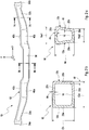
- Figures 2a, 2b and 2c display a front view of the axle 10 composed of two half shells 12a, 12b shown in Figure 1 , a cross section of the middle section 30 of the axle 10, and a cross section of the axle 10 in an end section 32.
- the axle 10 shows in the middle section 30 a nearly rectangular cross section with an overall height Ch and an overall width Cw, with side walls 20a, 20b which extend in the z-direction and an upper wall 20c and a lower wall 20d which extend in the x-direction.
- the average thickness dz of the side walls 20a, 20b is smaller than the average thickness dx of the upper and lower side walls 20c, 20d.
- the upper and lower walls 20c, 20d are slightly inclined from their outer edges towards the middle and have a maximum in height in the middle of each wall 20c, 20d.
- the half shells 12a, 12b are joint at an interface 16 at the upper and lower walls 20c, 20d, which interface 16 is arranged in the height maximum of the upper and lower walls 20c, 20d.
- the cross section of the axle 10 has a broader upper wall 20c with an overall width Nw1 and a shorter lower wall 20d with an overall width Nw2 and an overall height Nh.
- the side walls 20a, 20b are bent outward according to the different lengths of the upper and lower walls 20c, 20d. Again, the average thickness dz of the side walls 20a, 20b is smaller than the average thickness dx of the upper and lower side walls 20c, 20d.
- the material thickness is non-uniform along the y-direction as well as along the x-direction and the z-direction.
- This non-uniformity in thickness can be generated by die forging of the half shells 12a, 12b in a well controlled manner.
- the two half shells 12a, 12b are joined by way of flash butt welding.
- Figure 3a depicts a perspective view of the half shell of Fig. 1 .
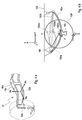
- Figure 3b shows roll movement effects of prior art system comprising a conventional massive forged axle 100 mounted to a frame body 120 of a vehicle.
- the axle 100 is connected to a leaf spring 110l at the left side and 110r at the right side via its spring plate (only the spring plate 142l on the left side is shown).
- the left and right wheels 102l and 102r can have a large difference in camber height 130h as well as a large difference in longitudinal movement 130w due to the deformation of the axle 100.
- Axle steering is in this example created by a downward bent leaf spring 110 with a large camber height 130h.
- axle body Due to the different lateral movement of the axle 100 between the left and right spring plates 1421 the axle body is rotated about the z-direction to give axle steering (seen by the longitudinal movement 130w) when a roll movement, i.e. a rotation about the x-direction is present.
- the torsional stiffness between the spring plates 142 have a big influence on the roll movement handling due to that the suspension of leaf springs (or air suspension, reaction rods or trailing arms) will introduce high torques in this area.
- the torques will deform the known forged axle 100 so that it will reduce the under steering effect from axle steering.
- the largest effects are usually observed on axles with a high swan neck.
- By using the inventive forged hollow axle 10 it is possible to increase the torsional stiffness (y-rot), e.g. about 250%, which advantageously maintains more of the desired under steering effects from the axle steering, hence increasing roll steering.
- Figure 4a shows a perspective view of the half shell of Fig. 1 .
- Figure 4b depicts a wind-up brake and bump travel motion of a prior art system.
- the typical front suspensions (leaf spring, air spring etc.) all show a specific wind-up centre 150wc and rotation point 160, from axle travelling at bump and brake handling.
- point 150bc indicates the top position of the wind-up centre of the leaf spring when driving over a bump with one wheel 102l, with 150b being the leaf spring during bump handling and 150n being the leaf spring during normal driving.
- Reference numeral 150w indicates a wind-up movement of the leaf spring with 150wc being the wind-up centre, i.e. a rotation centre, of the leaf spring during braking.
- the broad vertical arrow indicates a force introduced by a bump, the thin horizontal arrow indicates a brake motion.
- the hollow axle 10 according to the invention gives possibilities to increase the torsional stiffness (y-rot) with at least 200% at the end section 32a, 32b (i.e. swan neck region). This advantageously increases the possibility to minimize steering errors at both bump and brake handling and provides a robust behaviour which is not depending on the swan neck height, as is the case for conventional axles.
- the axle according to the invention allows for a robust steering behaviour at bump and brake handling.
- Figures 5a and 5b depict characteristics showing the improvement in brake pulling reduction Bs in degrees as a function of brake sequence B ( Fig. 5a ) and roll steering behaviour Rs in degrees as a function of axle roll angle A in degrees ( Fig. 5b ).
- FIG. 5b illustrates an increased under steering of the axle.
- An axle roll angle Aa between ⁇ 4 deg gives in general about the double of the under steering angle for a hollow axle according to the invention (curve R10) and a conventional axle (curve R100).
- Figures 6a and 6b illustrate steps of a joining process of two half shells 12a, 12b for forming a hollow axle 10 according to the invention.
- Two half shells 12a, 12b are formed by die forging where material in the half shells is distributed in a defined way.
- the two half shells 12a, 12b are turned to face each other with their open sides and are clamped into fixtures which are connected to a welding transformer 200.
- One of the clamp fixtures is mounted on a slide which is programmed to move towards the stationary clamp fixture at a controlled rate. While the clamp fixture is moving, the transformer 200 is energized and the two half shells 12a, 12b touch.
- the electrical current applied to the half shells 12a, 12b generates a flashing or arcing across the interface of the two butting ends of the half shells 12a, 12b.
- the flashing action increases to the point of bringing the material of the half shells 12a, 12b at the interface to a plastic state.
- the slide driving the clamp fixture rapidly accelerates, forging the half shells 12a, 12b to form a joint essentially as strong as the parent metal without the aid of any filler material.
- the melted metal and impurities are forced out of the welding zone so that the inner material at the joint is solid and free of oxides or cast metal.
- the forces required for flash-butt welding are established by the forge strength of the materials being welded.
- using a hollow forged axle provides increased important stiffness characteristics in a defined and locally varying way for a robust front suspension design. Due to the improved stiffness characteristics, it is also possible to increase the control of under steering and over steering effects at roll handling as well as minimizing steering errors from bump and brake handling. Further the necessary geometry variations and number of components at big variations of axle geometry and installation heights can be simplified. The invention is particularly useful for trucks with steered axles.
Landscapes
- Engineering & Computer Science (AREA)
- Mechanical Engineering (AREA)
- Vehicle Body Suspensions (AREA)
Claims (10)
- Essieu creux forgé (10), en particulier un essieu orientable, conçu pour un véhicule utilitaire, l'essieu (10) ayant une extension longitudinale principale dans la direction y (y), une largeur dans la direction x (x) et une hauteur dans la direction z (z) et étant composé d'au moins deux demi-coquilles (12a, 12b) reliées de manière fixe au niveau d'une interface (16) qui s'étend le long de son extension longitudinale (y), où une épaisseur de matériau (d) dans l'une et/ou l'autre des demi-coquilles (12a, 12b) est distribuée dans l'extension longitudinale principale (y) et dans l'une et/ou l'autre de la largeur (x) et de la hauteur (z) pour fournir une relation prédéterminée d'une rigidité en torsion et d'une rigidité en flexion dans une ou plusieurs direction(s) spatiale(s) (x, y, z) dans des sections d'essieu (30, 32a, 32b), lesdites sections d'essieu (30, 32a, 32b) comprenant une section médiane (30) et une section d'extrémité (32), l'essieu creux forgé étant caractérisé en ce que le matériau est distribué de manière à rendre la rigidité en torsion plus grande que la rigidité en flexion dans la direction x dans la section médiane (30) et de manière à rendre la rigidité en flexion dans la direction z plus grande que la rigidité en flexion dans la direction x dans la section d'extrémité (32) à l'extérieur de la section médiane (30).
- Essieu selon l'une quelconque des revendications précédentes, caractérisé en ce que la distribution de matériau a une épaisseur moyenne le long d'une extension dans la direction z qui est inférieure à une épaisseur moyenne le long d'une extension dans la direction x.
- Essieu selon l'une quelconque des revendications précédentes, caractérisé en ce que les demi-coquilles (12a, 12b) sont reliées par soudage en bout par étincelage.
- Essieu selon l'une quelconque des revendications précédentes, caractérisé en ce que la rigidité en torsion et la rigidité en flexion diffèrent au moins par un facteur 1,5, en particulier au moins par un facteur 2.
- Essieu selon l'une quelconque des revendications précédentes, caractérisé en ce que la section médiane (30) est agencée entre des positions de ressort (42a, 42b) de l'essieu (10).
- Essieu selon l'une quelconque des revendications précédentes, caractérisé en ce que la section d'extrémité (32a, 32b) est une section de col de cygne de l'essieu (10).
- Essieu selon l'une quelconque des revendications précédentes, caractérisé par une conception d'un essieu orientable (10) comprenant des logements de pivot d'attelage (36a, 36b) au niveau de ses extrémités libres, et par une conception d'un essieu non entraînable (10) ou d'un essieu (10) entraînable par roues motrices individuelles.
- Essieu selon la revendication 7, caractérisé par une conception d'un essieu avant.
- Procédé de fabrication d'un essieu creux forgé (10), en particulier un essieu orientable, selon l'une quelconque des revendications précédentes, dans lequel il comprend les étapes qui consistent :- à préparer une première demi-coquille (12a) et une deuxième demi-coquille (12b) par forgeage par matriçage de manière à établir une distribution de matériau qui donne une épaisseur de matériau (d) dans l'une et/ou l'autre des demi-coquilles (12a, 12b) pour fournir une relation prédéterminée d'une rigidité en torsion et d'une rigidité en flexion dans une ou plusieurs direction(s) spatiale(s) (x, y, z) dans des sections d'essieu, lesdites sections d'essieu comprenant une section médiane (30) et une section d'extrémité (32), où le matériau est distribué de manière à rendre la rigidité en torsion plus grande que la rigidité en flexion dans la direction x dans la section médiane (30) et de manière à rendre la rigidité en flexion dans la direction z plus grande que la rigidité en flexion dans la direction x dans la section d'extrémité (32) à l'extérieur de la section médiane (30) ; et- à relier les demi-coquilles (12a, 12b) par soudage en bout par étincelage pour maintenir les propriétés de matériau des demi-coquilles (12a, 12b) après le soudage.
- Véhicule comprenant un essieu creux orientable forgé (10) selon l'une quelconque des revendications 1 à 8.
Applications Claiming Priority (1)
| Application Number | Priority Date | Filing Date | Title |
|---|---|---|---|
| PCT/SE2011/000199 WO2013066219A1 (fr) | 2011-11-01 | 2011-11-01 | Essieu creux forgé et son procédé de fabrication |
Publications (3)
| Publication Number | Publication Date |
|---|---|
| EP2773473A1 EP2773473A1 (fr) | 2014-09-10 |
| EP2773473A4 EP2773473A4 (fr) | 2016-01-20 |
| EP2773473B1 true EP2773473B1 (fr) | 2017-06-28 |
Family
ID=48192440
Family Applications (1)
| Application Number | Title | Priority Date | Filing Date |
|---|---|---|---|
| EP11875011.6A Active EP2773473B1 (fr) | 2011-11-01 | 2011-11-01 | Essieu creux forgé et son procédé de fabrication |
Country Status (3)
| Country | Link |
|---|---|
| US (1) | US9428010B2 (fr) |
| EP (1) | EP2773473B1 (fr) |
| WO (1) | WO2013066219A1 (fr) |
Families Citing this family (4)
| Publication number | Priority date | Publication date | Assignee | Title |
|---|---|---|---|---|
| US9527368B2 (en) * | 2012-07-03 | 2016-12-27 | Pantero Technologies Inc. | Semi-independent suspension system for a low-floor vechicle |
| CN106623741A (zh) * | 2016-06-17 | 2017-05-10 | 湖北三环车桥有限公司 | 一种镂空汽车前轴的锻造方法 |
| MX2019011589A (es) * | 2017-04-05 | 2019-11-08 | Nippon Steel Corp | Viga de eje delantero y metodo de produccion de la misma. |
| US12208645B2 (en) * | 2022-03-31 | 2025-01-28 | Caterpillar Inc. | Front axle for mining machines |
Family Cites Families (13)
| Publication number | Priority date | Publication date | Assignee | Title |
|---|---|---|---|---|
| US1721695A (en) | 1925-12-19 | 1929-07-23 | Thompson Prod Inc | Method of making tubular front axles |
| US2685479A (en) * | 1944-11-25 | 1954-08-03 | Rockwell Spring & Axle Co | Tubular axle beam |
| US2911262A (en) * | 1955-07-01 | 1959-11-03 | Superior Steel & Malleable Cas | Vehicle axle |
| DE1580640A1 (de) | 1965-08-30 | 1970-12-17 | North American Rockwell | Anhaengerachse |
| FR2054335A5 (fr) | 1969-07-23 | 1971-04-16 | Maschf Augsburg Nuernberg Ag | |
| DE2049889C3 (de) | 1970-10-10 | 1979-01-25 | Eumuco Ag Fuer Maschinenbau, 5090 Leverkusen | Verfahren zum Herstellen einer halbschaligen Brückenhälfte für eine Achsbrücke an Kraftfahrzeugen, insbesondere Lastkraftwagen |
| US6196563B1 (en) * | 1998-12-11 | 2001-03-06 | Harold W. Haycraft | Reversible high ground clearance steering axle |
| SE516792C2 (sv) | 2001-03-23 | 2002-03-05 | Volvo Lastvagnar Ab | Ihåligt konstruktionselement och metod för dess tillverkning |
| US6585331B2 (en) * | 2001-09-06 | 2003-07-01 | Meritor Heavy Vehicle Technology, Llc | Tubular axle beam |
| US6799811B1 (en) | 2002-05-01 | 2004-10-05 | Dana Corporation | Steer axle with kingpin boss |
| SE526524C2 (sv) * | 2003-06-06 | 2005-10-04 | Volvo Lastvagnar Ab | Metod för tillverkning av ihåliga konstruktionselement |
| US7325821B2 (en) * | 2006-06-28 | 2008-02-05 | Dana Corporation | Suspension mounting system and a method of assembling the same |
| DE102007025684A1 (de) | 2007-06-01 | 2008-04-30 | Daimler Ag | Lenkbare Achse für ein Kraftfahrzeug |
-
2011
- 2011-11-01 EP EP11875011.6A patent/EP2773473B1/fr active Active
- 2011-11-01 US US14/357,961 patent/US9428010B2/en active Active
- 2011-11-01 WO PCT/SE2011/000199 patent/WO2013066219A1/fr not_active Ceased
Also Published As
| Publication number | Publication date |
|---|---|
| US20150130262A1 (en) | 2015-05-14 |
| EP2773473A4 (fr) | 2016-01-20 |
| US9428010B2 (en) | 2016-08-30 |
| WO2013066219A1 (fr) | 2013-05-10 |
| EP2773473A1 (fr) | 2014-09-10 |
Similar Documents
| Publication | Publication Date | Title |
|---|---|---|
| US5507518A (en) | Torsion beam type suspension and method for production thereof | |
| RU2497690C2 (ru) | Конструктивный двутавровый рычаг автомобильной подвески | |
| EP3112193B1 (fr) | Procédé d'obtention d'un bras de suspension pour véhicules automobiles et bras de suspension | |
| CN103153645B (zh) | 拼合式车辆轴 | |
| CN100457482C (zh) | 工字梁结构汽车悬架臂 | |
| DE102006041567B4 (de) | Verbundlenkerachsaufhängungen | |
| US7763825B2 (en) | Axle beam for industrial vehicle, method of manufacturing the same and rear steering apparatus | |
| US11420472B2 (en) | Front axle beam and production method thereof | |
| WO2010004370A1 (fr) | Traverse pour suspension d'essieu de torsion arrière de véhicule à moteur et procédé de production | |
| EP2773473B1 (fr) | Essieu creux forgé et son procédé de fabrication | |
| KR101230592B1 (ko) | 일체형 트레일링 암 및 그 제조방법 | |
| US8777245B2 (en) | Optimized wall thickness torque rod | |
| JP6488096B2 (ja) | 構造用i形ビームの自動車用サスペンションアーム | |
| US7726027B2 (en) | Method of manufacturing hollow structural elements | |
| KR102244923B1 (ko) | 차량용 현가암의 제조방법 | |
| KR102449205B1 (ko) | 복합소재를 이용한 컨트롤암의 제조방법 및 그 방법으로 제조된 컨트롤암 | |
| EP1933998A1 (fr) | Procede pour produire un composant de moyeu, et composant de moyeu ainsi produit | |
| US6641150B1 (en) | Fabricated steer axle assembly | |
| WO2017158535A1 (fr) | Transverse d'ensemble essieu pour un véhicule utilitaire léger | |
| DE202016105743U1 (de) | Hinterachsaufhängung für ein Fahrzeug | |
| DE102016219140A1 (de) | Hinterachsaufhängung für ein Fahrzeug | |
| KR102799519B1 (ko) | 차량용 현가장치의 토션 빔 제조 방법 및 차량용 현가장치 | |
| DE102016219138A1 (de) | Hinterachsaufhängung für ein Fahrzeug |
Legal Events
| Date | Code | Title | Description |
|---|---|---|---|
| PUAI | Public reference made under article 153(3) epc to a published international application that has entered the european phase |
Free format text: ORIGINAL CODE: 0009012 |
|
| 17P | Request for examination filed |
Effective date: 20140602 |
|
| AK | Designated contracting states |
Kind code of ref document: A1 Designated state(s): AL AT BE BG CH CY CZ DE DK EE ES FI FR GB GR HR HU IE IS IT LI LT LU LV MC MK MT NL NO PL PT RO RS SE SI SK SM TR |
|
| DAX | Request for extension of the european patent (deleted) | ||
| RA4 | Supplementary search report drawn up and despatched (corrected) |
Effective date: 20151223 |
|
| RIC1 | Information provided on ipc code assigned before grant |
Ipc: B21K 25/00 20060101ALI20151217BHEP Ipc: B21K 1/06 20060101AFI20151217BHEP Ipc: B21K 1/12 20060101ALI20151217BHEP Ipc: B60B 35/08 20060101ALI20151217BHEP |
|
| GRAP | Despatch of communication of intention to grant a patent |
Free format text: ORIGINAL CODE: EPIDOSNIGR1 |
|
| INTG | Intention to grant announced |
Effective date: 20170120 |
|
| GRAS | Grant fee paid |
Free format text: ORIGINAL CODE: EPIDOSNIGR3 |
|
| GRAA | (expected) grant |
Free format text: ORIGINAL CODE: 0009210 |
|
| AK | Designated contracting states |
Kind code of ref document: B1 Designated state(s): AL AT BE BG CH CY CZ DE DK EE ES FI FR GB GR HR HU IE IS IT LI LT LU LV MC MK MT NL NO PL PT RO RS SE SI SK SM TR |
|
| REG | Reference to a national code |
Ref country code: GB Ref legal event code: FG4D |
|
| REG | Reference to a national code |
Ref country code: CH Ref legal event code: EP |
|
| REG | Reference to a national code |
Ref country code: AT Ref legal event code: REF Ref document number: 904404 Country of ref document: AT Kind code of ref document: T Effective date: 20170715 |
|
| REG | Reference to a national code |
Ref country code: IE Ref legal event code: FG4D |
|
| REG | Reference to a national code |
Ref country code: DE Ref legal event code: R096 Ref document number: 602011039232 Country of ref document: DE |
|
| PG25 | Lapsed in a contracting state [announced via postgrant information from national office to epo] |
Ref country code: HR Free format text: LAPSE BECAUSE OF FAILURE TO SUBMIT A TRANSLATION OF THE DESCRIPTION OR TO PAY THE FEE WITHIN THE PRESCRIBED TIME-LIMIT Effective date: 20170628 Ref country code: GR Free format text: LAPSE BECAUSE OF FAILURE TO SUBMIT A TRANSLATION OF THE DESCRIPTION OR TO PAY THE FEE WITHIN THE PRESCRIBED TIME-LIMIT Effective date: 20170929 Ref country code: FI Free format text: LAPSE BECAUSE OF FAILURE TO SUBMIT A TRANSLATION OF THE DESCRIPTION OR TO PAY THE FEE WITHIN THE PRESCRIBED TIME-LIMIT Effective date: 20170628 Ref country code: NO Free format text: LAPSE BECAUSE OF FAILURE TO SUBMIT A TRANSLATION OF THE DESCRIPTION OR TO PAY THE FEE WITHIN THE PRESCRIBED TIME-LIMIT Effective date: 20170928 Ref country code: LT Free format text: LAPSE BECAUSE OF FAILURE TO SUBMIT A TRANSLATION OF THE DESCRIPTION OR TO PAY THE FEE WITHIN THE PRESCRIBED TIME-LIMIT Effective date: 20170628 |
|
| REG | Reference to a national code |
Ref country code: NL Ref legal event code: MP Effective date: 20170628 |
|
| REG | Reference to a national code |
Ref country code: LT Ref legal event code: MG4D |
|
| REG | Reference to a national code |
Ref country code: AT Ref legal event code: MK05 Ref document number: 904404 Country of ref document: AT Kind code of ref document: T Effective date: 20170628 |
|
| REG | Reference to a national code |
Ref country code: FR Ref legal event code: PLFP Year of fee payment: 7 |
|
| PG25 | Lapsed in a contracting state [announced via postgrant information from national office to epo] |
Ref country code: RS Free format text: LAPSE BECAUSE OF FAILURE TO SUBMIT A TRANSLATION OF THE DESCRIPTION OR TO PAY THE FEE WITHIN THE PRESCRIBED TIME-LIMIT Effective date: 20170628 Ref country code: NL Free format text: LAPSE BECAUSE OF FAILURE TO SUBMIT A TRANSLATION OF THE DESCRIPTION OR TO PAY THE FEE WITHIN THE PRESCRIBED TIME-LIMIT Effective date: 20170628 Ref country code: LV Free format text: LAPSE BECAUSE OF FAILURE TO SUBMIT A TRANSLATION OF THE DESCRIPTION OR TO PAY THE FEE WITHIN THE PRESCRIBED TIME-LIMIT Effective date: 20170628 Ref country code: SE Free format text: LAPSE BECAUSE OF FAILURE TO SUBMIT A TRANSLATION OF THE DESCRIPTION OR TO PAY THE FEE WITHIN THE PRESCRIBED TIME-LIMIT Effective date: 20170628 Ref country code: BG Free format text: LAPSE BECAUSE OF FAILURE TO SUBMIT A TRANSLATION OF THE DESCRIPTION OR TO PAY THE FEE WITHIN THE PRESCRIBED TIME-LIMIT Effective date: 20170928 |
|
| PG25 | Lapsed in a contracting state [announced via postgrant information from national office to epo] |
Ref country code: CZ Free format text: LAPSE BECAUSE OF FAILURE TO SUBMIT A TRANSLATION OF THE DESCRIPTION OR TO PAY THE FEE WITHIN THE PRESCRIBED TIME-LIMIT Effective date: 20170628 Ref country code: EE Free format text: LAPSE BECAUSE OF FAILURE TO SUBMIT A TRANSLATION OF THE DESCRIPTION OR TO PAY THE FEE WITHIN THE PRESCRIBED TIME-LIMIT Effective date: 20170628 Ref country code: RO Free format text: LAPSE BECAUSE OF FAILURE TO SUBMIT A TRANSLATION OF THE DESCRIPTION OR TO PAY THE FEE WITHIN THE PRESCRIBED TIME-LIMIT Effective date: 20170628 Ref country code: SK Free format text: LAPSE BECAUSE OF FAILURE TO SUBMIT A TRANSLATION OF THE DESCRIPTION OR TO PAY THE FEE WITHIN THE PRESCRIBED TIME-LIMIT Effective date: 20170628 Ref country code: AT Free format text: LAPSE BECAUSE OF FAILURE TO SUBMIT A TRANSLATION OF THE DESCRIPTION OR TO PAY THE FEE WITHIN THE PRESCRIBED TIME-LIMIT Effective date: 20170628 |
|
| PG25 | Lapsed in a contracting state [announced via postgrant information from national office to epo] |
Ref country code: SM Free format text: LAPSE BECAUSE OF FAILURE TO SUBMIT A TRANSLATION OF THE DESCRIPTION OR TO PAY THE FEE WITHIN THE PRESCRIBED TIME-LIMIT Effective date: 20170628 Ref country code: IS Free format text: LAPSE BECAUSE OF FAILURE TO SUBMIT A TRANSLATION OF THE DESCRIPTION OR TO PAY THE FEE WITHIN THE PRESCRIBED TIME-LIMIT Effective date: 20171028 Ref country code: IT Free format text: LAPSE BECAUSE OF FAILURE TO SUBMIT A TRANSLATION OF THE DESCRIPTION OR TO PAY THE FEE WITHIN THE PRESCRIBED TIME-LIMIT Effective date: 20170628 Ref country code: PL Free format text: LAPSE BECAUSE OF FAILURE TO SUBMIT A TRANSLATION OF THE DESCRIPTION OR TO PAY THE FEE WITHIN THE PRESCRIBED TIME-LIMIT Effective date: 20170628 Ref country code: ES Free format text: LAPSE BECAUSE OF FAILURE TO SUBMIT A TRANSLATION OF THE DESCRIPTION OR TO PAY THE FEE WITHIN THE PRESCRIBED TIME-LIMIT Effective date: 20170628 |
|
| REG | Reference to a national code |
Ref country code: DE Ref legal event code: R097 Ref document number: 602011039232 Country of ref document: DE |
|
| PG25 | Lapsed in a contracting state [announced via postgrant information from national office to epo] |
Ref country code: DK Free format text: LAPSE BECAUSE OF FAILURE TO SUBMIT A TRANSLATION OF THE DESCRIPTION OR TO PAY THE FEE WITHIN THE PRESCRIBED TIME-LIMIT Effective date: 20170628 |
|
| PLBE | No opposition filed within time limit |
Free format text: ORIGINAL CODE: 0009261 |
|
| STAA | Information on the status of an ep patent application or granted ep patent |
Free format text: STATUS: NO OPPOSITION FILED WITHIN TIME LIMIT |
|
| 26N | No opposition filed |
Effective date: 20180329 |
|
| PG25 | Lapsed in a contracting state [announced via postgrant information from national office to epo] |
Ref country code: MC Free format text: LAPSE BECAUSE OF FAILURE TO SUBMIT A TRANSLATION OF THE DESCRIPTION OR TO PAY THE FEE WITHIN THE PRESCRIBED TIME-LIMIT Effective date: 20170628 |
|
| GBPC | Gb: european patent ceased through non-payment of renewal fee |
Effective date: 20171101 |
|
| PG25 | Lapsed in a contracting state [announced via postgrant information from national office to epo] |
Ref country code: LI Free format text: LAPSE BECAUSE OF NON-PAYMENT OF DUE FEES Effective date: 20171130 Ref country code: CH Free format text: LAPSE BECAUSE OF NON-PAYMENT OF DUE FEES Effective date: 20171130 |
|
| PG25 | Lapsed in a contracting state [announced via postgrant information from national office to epo] |
Ref country code: LU Free format text: LAPSE BECAUSE OF NON-PAYMENT OF DUE FEES Effective date: 20171101 Ref country code: SI Free format text: LAPSE BECAUSE OF FAILURE TO SUBMIT A TRANSLATION OF THE DESCRIPTION OR TO PAY THE FEE WITHIN THE PRESCRIBED TIME-LIMIT Effective date: 20170628 |
|
| REG | Reference to a national code |
Ref country code: BE Ref legal event code: MM Effective date: 20171130 |
|
| REG | Reference to a national code |
Ref country code: IE Ref legal event code: MM4A |
|
| PG25 | Lapsed in a contracting state [announced via postgrant information from national office to epo] |
Ref country code: MT Free format text: LAPSE BECAUSE OF NON-PAYMENT OF DUE FEES Effective date: 20171101 |
|
| PG25 | Lapsed in a contracting state [announced via postgrant information from national office to epo] |
Ref country code: IE Free format text: LAPSE BECAUSE OF NON-PAYMENT OF DUE FEES Effective date: 20171101 |
|
| PG25 | Lapsed in a contracting state [announced via postgrant information from national office to epo] |
Ref country code: BE Free format text: LAPSE BECAUSE OF NON-PAYMENT OF DUE FEES Effective date: 20171130 Ref country code: GB Free format text: LAPSE BECAUSE OF NON-PAYMENT OF DUE FEES Effective date: 20171101 |
|
| PG25 | Lapsed in a contracting state [announced via postgrant information from national office to epo] |
Ref country code: HU Free format text: LAPSE BECAUSE OF FAILURE TO SUBMIT A TRANSLATION OF THE DESCRIPTION OR TO PAY THE FEE WITHIN THE PRESCRIBED TIME-LIMIT; INVALID AB INITIO Effective date: 20111101 |
|
| PG25 | Lapsed in a contracting state [announced via postgrant information from national office to epo] |
Ref country code: CY Free format text: LAPSE BECAUSE OF NON-PAYMENT OF DUE FEES Effective date: 20170628 |
|
| PG25 | Lapsed in a contracting state [announced via postgrant information from national office to epo] |
Ref country code: MK Free format text: LAPSE BECAUSE OF FAILURE TO SUBMIT A TRANSLATION OF THE DESCRIPTION OR TO PAY THE FEE WITHIN THE PRESCRIBED TIME-LIMIT Effective date: 20170628 |
|
| PG25 | Lapsed in a contracting state [announced via postgrant information from national office to epo] |
Ref country code: TR Free format text: LAPSE BECAUSE OF FAILURE TO SUBMIT A TRANSLATION OF THE DESCRIPTION OR TO PAY THE FEE WITHIN THE PRESCRIBED TIME-LIMIT Effective date: 20170628 |
|
| PG25 | Lapsed in a contracting state [announced via postgrant information from national office to epo] |
Ref country code: PT Free format text: LAPSE BECAUSE OF FAILURE TO SUBMIT A TRANSLATION OF THE DESCRIPTION OR TO PAY THE FEE WITHIN THE PRESCRIBED TIME-LIMIT Effective date: 20170628 |
|
| PG25 | Lapsed in a contracting state [announced via postgrant information from national office to epo] |
Ref country code: AL Free format text: LAPSE BECAUSE OF FAILURE TO SUBMIT A TRANSLATION OF THE DESCRIPTION OR TO PAY THE FEE WITHIN THE PRESCRIBED TIME-LIMIT Effective date: 20170628 |
|
| PGFP | Annual fee paid to national office [announced via postgrant information from national office to epo] |
Ref country code: FR Payment date: 20241126 Year of fee payment: 14 |
|
| PGFP | Annual fee paid to national office [announced via postgrant information from national office to epo] |
Ref country code: DE Payment date: 20251126 Year of fee payment: 15 |