EP2773875B1 - Perfectionnements apportés ou se rapportant à des éléments de fixation - Google Patents
Perfectionnements apportés ou se rapportant à des éléments de fixation Download PDFInfo
- Publication number
- EP2773875B1 EP2773875B1 EP11875195.7A EP11875195A EP2773875B1 EP 2773875 B1 EP2773875 B1 EP 2773875B1 EP 11875195 A EP11875195 A EP 11875195A EP 2773875 B1 EP2773875 B1 EP 2773875B1
- Authority
- EP
- European Patent Office
- Prior art keywords
- aperture
- washer
- fastener
- main body
- blind fastener
- Prior art date
- Legal status (The legal status is an assumption and is not a legal conclusion. Google has not performed a legal analysis and makes no representation as to the accuracy of the status listed.)
- Active
Links
Images




Classifications
-
- F—MECHANICAL ENGINEERING; LIGHTING; HEATING; WEAPONS; BLASTING
- F16—ENGINEERING ELEMENTS AND UNITS; GENERAL MEASURES FOR PRODUCING AND MAINTAINING EFFECTIVE FUNCTIONING OF MACHINES OR INSTALLATIONS; THERMAL INSULATION IN GENERAL
- F16B—DEVICES FOR FASTENING OR SECURING CONSTRUCTIONAL ELEMENTS OR MACHINE PARTS TOGETHER, e.g. NAILS, BOLTS, CIRCLIPS, CLAMPS, CLIPS OR WEDGES; JOINTS OR JOINTING
- F16B5/00—Joining sheets or plates, e.g. panels, to one another or to strips or bars parallel to them
- F16B5/06—Joining sheets or plates, e.g. panels, to one another or to strips or bars parallel to them by means of clamps or clips
- F16B5/0607—Joining sheets or plates, e.g. panels, to one another or to strips or bars parallel to them by means of clamps or clips joining sheets or plates to each other
- F16B5/0621—Joining sheets or plates, e.g. panels, to one another or to strips or bars parallel to them by means of clamps or clips joining sheets or plates to each other in parallel relationship
-
- F—MECHANICAL ENGINEERING; LIGHTING; HEATING; WEAPONS; BLASTING
- F16—ENGINEERING ELEMENTS AND UNITS; GENERAL MEASURES FOR PRODUCING AND MAINTAINING EFFECTIVE FUNCTIONING OF MACHINES OR INSTALLATIONS; THERMAL INSULATION IN GENERAL
- F16B—DEVICES FOR FASTENING OR SECURING CONSTRUCTIONAL ELEMENTS OR MACHINE PARTS TOGETHER, e.g. NAILS, BOLTS, CIRCLIPS, CLAMPS, CLIPS OR WEDGES; JOINTS OR JOINTING
- F16B33/00—Features common to bolt and nut
- F16B33/002—Means for preventing rotation of screw-threaded elements
-
- F—MECHANICAL ENGINEERING; LIGHTING; HEATING; WEAPONS; BLASTING
- F16—ENGINEERING ELEMENTS AND UNITS; GENERAL MEASURES FOR PRODUCING AND MAINTAINING EFFECTIVE FUNCTIONING OF MACHINES OR INSTALLATIONS; THERMAL INSULATION IN GENERAL
- F16B—DEVICES FOR FASTENING OR SECURING CONSTRUCTIONAL ELEMENTS OR MACHINE PARTS TOGETHER, e.g. NAILS, BOLTS, CIRCLIPS, CLAMPS, CLIPS OR WEDGES; JOINTS OR JOINTING
- F16B35/00—Screw-bolts; Stay-bolts; Screw-threaded studs; Screws; Set screws
- F16B35/04—Screw-bolts; Stay-bolts; Screw-threaded studs; Screws; Set screws with specially-shaped head or shaft in order to fix the bolt on or in an object
- F16B35/06—Specially-shaped heads
-
- F—MECHANICAL ENGINEERING; LIGHTING; HEATING; WEAPONS; BLASTING
- F16—ENGINEERING ELEMENTS AND UNITS; GENERAL MEASURES FOR PRODUCING AND MAINTAINING EFFECTIVE FUNCTIONING OF MACHINES OR INSTALLATIONS; THERMAL INSULATION IN GENERAL
- F16B—DEVICES FOR FASTENING OR SECURING CONSTRUCTIONAL ELEMENTS OR MACHINE PARTS TOGETHER, e.g. NAILS, BOLTS, CIRCLIPS, CLAMPS, CLIPS OR WEDGES; JOINTS OR JOINTING
- F16B43/00—Washers or equivalent devices; Other devices for supporting bolt-heads or nuts
- F16B43/02—Washers or equivalent devices; Other devices for supporting bolt-heads or nuts with special provisions for engaging surfaces which are not perpendicular to a bolt axis or do not surround the bolt
- F16B43/025—Washers or equivalent devices; Other devices for supporting bolt-heads or nuts with special provisions for engaging surfaces which are not perpendicular to a bolt axis or do not surround the bolt for surfaces not surrounding the bolt, e.g. hook adaptors for bolts
-
- F—MECHANICAL ENGINEERING; LIGHTING; HEATING; WEAPONS; BLASTING
- F16—ENGINEERING ELEMENTS AND UNITS; GENERAL MEASURES FOR PRODUCING AND MAINTAINING EFFECTIVE FUNCTIONING OF MACHINES OR INSTALLATIONS; THERMAL INSULATION IN GENERAL
- F16B—DEVICES FOR FASTENING OR SECURING CONSTRUCTIONAL ELEMENTS OR MACHINE PARTS TOGETHER, e.g. NAILS, BOLTS, CIRCLIPS, CLAMPS, CLIPS OR WEDGES; JOINTS OR JOINTING
- F16B5/00—Joining sheets or plates, e.g. panels, to one another or to strips or bars parallel to them
- F16B5/02—Joining sheets or plates, e.g. panels, to one another or to strips or bars parallel to them by means of fastening members using screw-thread
- F16B5/0208—Joining sheets or plates, e.g. panels, to one another or to strips or bars parallel to them by means of fastening members using screw-thread using panel fasteners, i.e. permanent attachments allowing for quick assembly
-
- H—ELECTRICITY
- H05—ELECTRIC TECHNIQUES NOT OTHERWISE PROVIDED FOR
- H05K—PRINTED CIRCUITS; CASINGS OR CONSTRUCTIONAL DETAILS OF ELECTRIC APPARATUS; MANUFACTURE OF ASSEMBLAGES OF ELECTRICAL COMPONENTS
- H05K7/00—Constructional details common to different types of electric apparatus
- H05K7/14—Mounting supporting structure in casing or on frame or rack
- H05K7/1485—Servers; Data center rooms, e.g. 19-inch computer racks
- H05K7/1488—Cabinets therefor, e.g. chassis or racks or mechanical interfaces between blades and support structures
- H05K7/1489—Cabinets therefor, e.g. chassis or racks or mechanical interfaces between blades and support structures characterized by the mounting of blades therein, e.g. brackets, rails, trays
-
- F—MECHANICAL ENGINEERING; LIGHTING; HEATING; WEAPONS; BLASTING
- F16—ENGINEERING ELEMENTS AND UNITS; GENERAL MEASURES FOR PRODUCING AND MAINTAINING EFFECTIVE FUNCTIONING OF MACHINES OR INSTALLATIONS; THERMAL INSULATION IN GENERAL
- F16B—DEVICES FOR FASTENING OR SECURING CONSTRUCTIONAL ELEMENTS OR MACHINE PARTS TOGETHER, e.g. NAILS, BOLTS, CIRCLIPS, CLAMPS, CLIPS OR WEDGES; JOINTS OR JOINTING
- F16B5/00—Joining sheets or plates, e.g. panels, to one another or to strips or bars parallel to them
- F16B5/06—Joining sheets or plates, e.g. panels, to one another or to strips or bars parallel to them by means of clamps or clips
- F16B5/0607—Joining sheets or plates, e.g. panels, to one another or to strips or bars parallel to them by means of clamps or clips joining sheets or plates to each other
- F16B5/0621—Joining sheets or plates, e.g. panels, to one another or to strips or bars parallel to them by means of clamps or clips joining sheets or plates to each other in parallel relationship
- F16B5/065—Joining sheets or plates, e.g. panels, to one another or to strips or bars parallel to them by means of clamps or clips joining sheets or plates to each other in parallel relationship the plates being one on top of the other and distanced from each other, e.g. by using protrusions to keep contact and distance
-
- Y—GENERAL TAGGING OF NEW TECHNOLOGICAL DEVELOPMENTS; GENERAL TAGGING OF CROSS-SECTIONAL TECHNOLOGIES SPANNING OVER SEVERAL SECTIONS OF THE IPC; TECHNICAL SUBJECTS COVERED BY FORMER USPC CROSS-REFERENCE ART COLLECTIONS [XRACs] AND DIGESTS
- Y10—TECHNICAL SUBJECTS COVERED BY FORMER USPC
- Y10T—TECHNICAL SUBJECTS COVERED BY FORMER US CLASSIFICATION
- Y10T24/00—Buckles, buttons, clasps, etc.
- Y10T24/34—Combined diverse multipart fasteners
Definitions
- the present invention relates to fasteners.
- the present invention is directed to a blind fastener that may be inserted from one side of two members requiring fastening or securing to each other, for example electronic equipment to a rack (such as used in the telecommunications, information technology ("IT”) security or professional audio industries), where access from another side of the two members is not available or at least is inconvenient.
- a blind fastener that may be inserted from one side of two members requiring fastening or securing to each other, for example electronic equipment to a rack (such as used in the telecommunications, information technology (“IT”) security or professional audio industries), where access from another side of the two members is not available or at least is inconvenient.
- IT information technology
- the racks normally are formed from 2 or 4 vertical elongate structures to form a cabinet type arrangement. Such racks are or can be closed on 3 or more sides, and the front side can have a door. As such, while it is possible to access any side by removing panels or similar it is often inconvenient, at least a time perspective. As such front access for install and removal of equipment and its fastening is the most desirable and convenient.
- the back side is normally reserved for electrical and network connections and similar.
- the two structures that form the front of the rack normally have a series of spaced apertures on the front presenting vertical face. These apertures are to secure, via fasteners, the equipment to the rack.
- the access to these apertures is normally only from this front, as access from the rear is either blocked by the or other equipment, or is too difficult. Side access is often blocked by side panels that enclose the rack, or is otherwise inconvenient.
- a captive fastener solution is shown in US6682282 and US20050019133 .
- They are used for fastening rack mount panels to equipment racks.
- These solutions at least have the disadvantage that they must be supplied already attached to the equipment to be installed. Thus whilst they are always attached to the equipment, there will be surplus such fasteners, for example sitting on equipment that is not installed. They also require custom mounts and therefore are not readily adaptable or transferable between pieces of equipment.
- a latch style fastener is shown in GB 1123733 where a knurled knob operates a latch tongue to engage and disengage the equipment from the structure. This is an easy way to engage and disengage the equipment from the rack. However, it again requires specialist fitting on the equipment and/or the rack.
- FR2354470 An assembly to hold a lining panel is shown in FR2354470 .
- This shows an assembly to hold a lining panel to coach work.
- the assembly uses bush parts in the lining panel that then engage with a snap pin in the coach work.
- the coach work may for example be in a vehicle.
- the system holds the equipment safely but requires using a ball and socket arrangement to allow removal and reattachment of the liner to the coach work.
- a number of these solutions also have sharp edges so they can easily damage equipment that is slide in and out past them, especially when the equipment is heavy and/or the rack is high populated with little room to move.
- the present invention may be said to broadly consist in a blind fastener (1) adapted to engage and hold a first member (2) to a second member (4), comprising or including,
- said main body has at least one stop surface thereon to under-engage behind and/or in front of said aperture of said first member.
- said main body has two said stop surfaces, at least one to under-engage in front of said aperture and at least one to under-engage behind said aperture.
- said main body has a pair of said stop surfaces to under-engage in front of said aperture, either side of said main body.
- said clipping tongue also has at least one stop surface to under-engage in front and/or behind said aperture.
- said washer has two such extensions to locate substantially either side of an axis of said mounting portion.
- said at least one extension is tapered so the more it is urged between said main body and clipping tongue the more it wedges the two apart.
- said member, washer and nut are preferably made from a glass fibre reinforced plastic such as nylon or similar plastics material.
- said mounting portion is patterned to engage said fastener thereon.
- said patterned engagement is threaded, and said fastener is patterned to engage thereon.
- an upper presenting region of said mounting portion is flattened to reduce damage to said any patterned engagement thereon.
- said washer is a friction fit onto said mounting portion.
- said friction fit is via said washer aperture.
- said fastener has a surface texture to enable finger tightening and also has profiling to engage with a tool (for example a Philips or Blade screwdriver).
- a tool for example a Philips or Blade screwdriver
- said clipping tongue is a re-curved extension of said main body with an elastic hinge between it and said main body to enable said biasing.
- said clipping tongue must be elastically deformed to allow said stopping surface(s) to engage behind said aperture.
- said washer has a relief between it and said clip member to allow prising apart of said two, for example by a screwdriver.
- said washer is relieved on a side facing said clip member to accommodate portions thereof in front of said first member aperture.
- said washer has a second relief on its external periphery to ease its removal from said mounting portion, by for example a finger nail or tool.
- said blind fastener is able to be reused.
- said clip member as least where it traverses from in front to behind said aperture conforms to an inner periphery of said aperture.
- said inner periphery is square or rectilinear in cross section.
- said inner periphery is curved, circular or arcuate.
- said clip member is dimensioned so as to fit said aperture regardless of whether its inner periphery is rectilinear or curved.
- said fastener is formed by plastic injection moulding.
- said first member is a rack structure and said second member is equipment to be secured thereto.
- said second member also has an aperture (“second member aperture”) therethrough for said fastener to pass through.
- said second member sits between said washer and said fastener.
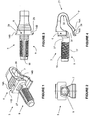
- a clip member 3 which is part of the assembly of line fastener 1.
- the clip member has a main body 6 and depending from the main body is a clipping tongue 7.
- the clipping tongue exists as a recurved extension 21 from the main body 6 and forms an elastic hinge 22 at or near the point of recurving.
- a mounting portion 9 which is patterned 17 for engagement with a complimentary patterned fastener 13 (shown in Figures 8a, b and 9a, b ).
- a complimentary patterned fastener 13 shown in Figures 8a, b and 9a, b
- it may be a clip or other type fit that may be used.
- the upper presenting surface 18 of the mounting portion 9 in the preferred embodiment is flattened. There are several reasons for this. The first reason is to prevent damage to the patterned 17 engagement. A further reason is to allow a stable location for temporarily seating equipment or second member 4 (not shown) on the mounting portion 9.
- stop surfaces 14 On the main body also is shown a number of stop surfaces 14. The purpose of these is to locate behind 15 the aperture 5 when engaged in the first into rack 24. This can best be seen in Figures 10 through 12 .
- stop surface 14a locates on the surface behind 15 the aperture 5.
- the stop surface 14b located at front 16 of the aperture 5 in the first member 2 or rack 24.
- this creates an initial engagement of the clip member 3 with the surfaces in front 16 and behind 15 of the aperture 5 to substantially prevent withdrawal of the clip member 3 from the aperture 5 without further bending or hinging of the clipping tongue 7.
- FIG. 1 In the preferred embodiment of the clip member 3, there is also present a scallop 27 opening toward the upwardly presenting as shown in Figures 1 and 4 .
- This scallop provides a location for the second member 4 or equipment 25. This provides the initial effect of preventing the second member 4 or equipment 25 from moving outward due to its sitting or its engagement within the scallop and thus provides some temporary security initially and also provides long term security once the fastener 13 is tightened thereon.
- a washer member 10 is shown in Figures 5a through 7b and acts as a planar bearing surface as well as a wedging component to lock the clip member 3 into the aperture 5.
- the washer member 10 presents a substantially planar face 30 which can bear on the back side of the second member 4 or equipment 25.
- a washer aperture 11 Present through the middle region of the washing member 10 is a washer aperture 11. This is dimensioned so as to provide a slight or actual interference fit with the cross section dimensions of the mounting portion 9. It may for example have feathered fingers or similar and engage with the patterning 17. This is done so as to temporarily lock the washer member 10 in place when located on the mounting portion 9 of the clip member 3.
- Extending from the back side surface of the washing member 10 is at least one extension 12.
- the washer and its extensions 12 seeks to oppose the forces on the clip member that try to extract it from the aperture 5.
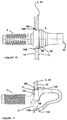
- the purpose of the extensions 12 will be understood when Figure 12 is viewed. These act as a wedge or cam and bear on the lower portions of the main body 6 and the upper portions of the clipping tongue 7 to urge the two apart and therefore locate the engaging surfaces against their surfaces of the aperture 5.
- extensions lock and prevent substantial movement of the clipping tongue 7 relative to the main body 6 so at least when the blind fastener 1 is assembled with the fastener 13 in place, the blind fastener 1 cannot be extracted from the aperture 5 without substantial deformation beyond the normal scope of its use. This extends beyond the normal scope of its use and design load characteristics.
- the back side surface of the washing member 10 also has relief 23 so as to provide as close a fit against the front presenting surfaces of the clip member 3.
- This can be seen in the cross section in Figure 12 .
- a second relief 32 (top and bottom) that allows for a tool or a user's fingernail to prise the washing member 10 away from the clip member 3 when installed thereon. This may be required when the two members have been engaged under force or a long period of time or under other circumstances such as the two stick or are wedged to each other. This may also be due to some partial deformation of the two, whether permanent or temporary.
- There may also be an interference fit between the relief 23 and those surfaces which engages with on the clip member 3 to further hold the washing member 10 to the clip member 3. Therefore the second relief 32 may also be required.
- a further second relief 32 is also shown on the lower surfaces of the washer member 10 in Figures 7a and 7b .
- FIG. 8a through 9b A preferred form of the fastener 13 is shown in Figures 8a through 9b .
- the fastener 13 has an internal pattern 17 that in this case is threaded to match the threading size of the mount portion 9.
- the fastener 13 has surface texturing 19, such as knurling present to increase the friction or contact between a user's fingers and the fastener 13 so as to allow finger tightening to as higher a degree as possible or as desired. Other surface texturing 19 different to that shown can be used and will be understood to be equivalent.
- the fastener 13 has a bearing surface 33 present as shown in Figures 8a and 9b which bears up or butts up against the outer presenting surface of the second member 4 or equipment 25 as would be understood when viewed with Figure
- the first member 2 or rack 24 can be seen in through section in Figures 10 and 11 .
- the aperture 5 through the first member 2 or rack 24 is shown in Figure 14a and the square or rectangular profile is shown in Figure 14c .
- An alternative profile shown in Figure 14b is circular. It will be understood the same principals of the invention can be applied to a clip member 3 whose stop surfaces 14, engagement surfaces 28 and side surfaces 29 are contoured and profiled so as to fit such a circular arcuate or curved aperture 5.
- the first member 2 has a surface behind 15 and a surface in front 16.
- the stop surfaces 14b engage on the surface in front 16 and the stop surfaces 14a engage on the surfaces behind 15 as shown in Figure 11 . Also shown here is the dimensioning between the stop surfaces 14a and 14b so as to be substantially the same as the through thickness from in front 16 to behind 15 of the aperture 5 in the first member 2 (or rack 24).
- the method of installation is such that the elastic hinge 22 end of the clip member 3 is located first into the aperture 5 and thereafter the clip member 3 is pushed through deforming the lower portion of the clipping tongue 7 until the stop surfaces 14a and 14b engage on their respective sides of the aperture 5 and first member 2 and likewise the side surfaces 29 and engaging surfaces 28 engage on their respective opposed regions.
- FIG. 14c The opposed regions for a square or rectangular aperture 5 are shown in Figure 14c as opposing regions 8a for the engagement surfaces 28 and 8b for the side surfaces 29.
- a curved or a circular aperture 5 shown in Figure 14b will have a similar such surfaces.
- FIG 12 there is shown the first member 2 (or rack 24) engaged as shown in Figures 10 and 11 on the clip member 3 and thereafter the washer member 10 is slid into position over the mounting portion 9 thereafter the second member 4 (or equipment 25) is slid over the mounting portion 9 so that the mounting portion engages in the second member aperture 26 (whether fully opened or closed aperture) but under action of gravity or by the user, the second member 4 or equipment 25 sits down to engage the scallop 27. Thereafter the fastener 13 is engaged on the mounting portion 9 and thereafter sandwiches the second member 4, washer 10 and clip member 3 to assemble and hold the equipment 25 to the rack 24.
- Shown in Figure 13 is the equipment rack and specifically shown is the first member 2, which may also be the normally vertically presenting legs of the rack 24 and shown located in place is a piece of equipment 25 and specifically the second member 4. Seen also are a plurality of apertures 5 for mounting of equipment at various heights in the rack.
- the present invention may be supplied as a kit of parts including the equipment 25 (or second member 4) and the blind fastener consisting at least of the clip member 6 and fastener 13. Additionally there may also be supplied the washing member 10.
- the rack 24 (or first member 2) that is supplied in the kit of parts with at least one blind fastener consisting of a clip member 3 and fastener 13 and preferably also the washing member 10.
Landscapes
- Engineering & Computer Science (AREA)
- General Engineering & Computer Science (AREA)
- Mechanical Engineering (AREA)
- Computer Hardware Design (AREA)
- Microelectronics & Electronic Packaging (AREA)
- Connection Of Plates (AREA)
- Roof Covering Using Slabs Or Stiff Sheets (AREA)
- Clamps And Clips (AREA)
Claims (15)
- Fixation en aveugle (1) adaptée pour engager et maintenir un premier élément (2) sur un second élément (4), ladite fixation en aveugle comprenant
un élément de clip (3) adapté pour être installé dans une première ouverture (5) sur ledit premier élément (2), ledit élément de clip (3) ayant
un corps principal (6) et une languette de blocage (7) qui s'étend depuis celui-ci, ladite languette de blocage (7) étant inclinée à l'écart dudit corps, de sorte que, lorsque ladite languette de blocage (7) et ledit corps principal (6) sont situés dans ladite ouverture, ledit corps principal (6) et ladite languette de blocage (7) engagent des zones opposées (8) de ladite ouverture (5), de sorte que, lorsqu'il est engagé, ledit élément de clip (3) ne puisse pas être retiré de ladite ouverture (5), et une partie de montage (9) qui s'étend vers l'extérieur depuis ledit corps principal (6), un élément de rondelle (10) avec une ouverture (11) à l'intérieur pour passer par-dessus ladite partie de montage (9), une fixation (13) destinée à s'engager sur ladite partie de montage (9) afin de fixer ledit élément de clip (3), l'élément de rondelle (10) et ledit second élément (4), sur ledit premier élément (2), ladite partie de montage (9) s'étende dans une partie dudit second élément (4), ou une extension de celui-ci, à fixer, et ladite fixation (13) maintienne ledit ensemble résultant afin de fixer ledit second élément (4) sur ledit premier élément (2), caractérisée en ce que ledit élément de rondelle (10) possède au moins une extension destinée à passer entre ledit corps principal (6) et ladite languette de blocage (7) afin de les séparer et de les pousser contre lesdites zones opposées (8), dans laquelle, pendant l'utilisation, ledit élément de clip (3) et l'élément de rondelle (10) sont montés dans ladite ouverture (11) sur ledit premier élément (2). - Fixation en aveugle (1) selon la revendication 1, dans laquelle ledit corps principal (6) possède au moins une surface d'arrêt (14) dessus destinée à sous-engager les surfaces situées derrière et/ou en face de ladite première ouverture (5).
- Fixation en aveugle (1) selon la revendication 2, dans laquelle ledit corps principal (6) possède une paire desdites surfaces d'arrêt (14) destinées au sous-engagement en face de ladite ouverture (5), de n'importe quel côté dudit corps principal (6).
- Fixation en aveugle (1) selon l'une quelconque des revendications 1 à 3, dans laquelle ladite languette de blocage (7) possède également au moins une surface d'arrêt (14) destinée au sous-engagement en face de et/ou derrière ladite ouverture (5).
- Fixation en aveugle (1) selon l'une quelconque des revendications 1 à 4, dans laquelle ladite rondelle (10) possède deux extensions (12) destinées à être placées sensiblement de n'importe quel côté d'un axe longitudinal dudit élément de clip (3).
- Fixation en aveugle (1) selon l'une quelconque des revendications 1 à 5, dans laquelle ladite partie de montage (9) est gravée afin d'engager ladite fixation dessus.
- Fixation en aveugle (1) selon la revendication 6, dans laquelle une zone de présentation supérieure de ladite partie de montage (9) est plate.
- Fixation en aveugle (1) selon l'une quelconque des revendications 1 à 7, dans laquelle ladite rondelle (10) est ajustée par frottement sur ladite partie de montage (9).
- Fixation en aveugle (1) selon la revendication 8, dans laquelle ledit ajustement par frottement s'effectue via ladite ouverture de rondelle (11).
- Fixation en aveugle (1) selon l'une quelconque des revendications 1 à 9, dans laquelle ladite languette de blocage (7) est une extension ré-incurvée dudit corps principal (6) avec une charnière élastique (22) entre celle-ci et ledit corps principal (6) de façon à permettre ladite inclinaison.
- Fixation en aveugle (1) selon l'une quelconque des revendications 1 à 10, dans laquelle ladite languette de blocage (7) doit être élastiquement déformée afin de permettre auxdites surfaces d'arrêt de s'engager derrière ladite ouverture (11).
- Fixation en aveugle (1) selon l'une quelconque des revendications 1 à 11, dans laquelle ladite rondelle (10) possède un relief (23) entre celle-ci et ledit élément de clip (3) afin de permettre la séparation de ladite rondelle (10) et dudit élément de clip (3), ou un relief (32) sur la périphérie externe destiné à faciliter son retrait de ladite partie de montage (9).
- Fixation en aveugle (1) selon l'une quelconque des revendications 1 à 12, dans laquelle ladite rondelle (10) est munie d'un relief sur un côté tourné vers ledit élément de clip (3) afin d'accueillir des parties de celle-ci en face de l'ouverture dudit premier élément.
- Fixation en aveugle (1) selon l'une quelconque des revendications 1 à 13, dans laquelle ledit élément de clip (3), au moins à l'endroit où il traverse d'avant en arrière ladite ouverture, se conforme à une périphérie interne de ladite ouverture (5).
- Fixation en aveugle (1) selon l'une quelconque des revendications 1 à 14, dans laquelle ledit second élément (4) se place entre ladite rondelle (10) et ladite fixation (13).
Applications Claiming Priority (1)
| Application Number | Priority Date | Filing Date | Title |
|---|---|---|---|
| PCT/NZ2011/000230 WO2013066193A1 (fr) | 2011-10-31 | 2011-10-31 | Perfectionnements apportés ou se rapportant à des éléments de fixation |
Publications (3)
| Publication Number | Publication Date |
|---|---|
| EP2773875A1 EP2773875A1 (fr) | 2014-09-10 |
| EP2773875A4 EP2773875A4 (fr) | 2015-07-29 |
| EP2773875B1 true EP2773875B1 (fr) | 2019-01-09 |
Family
ID=48192425
Family Applications (1)
| Application Number | Title | Priority Date | Filing Date |
|---|---|---|---|
| EP11875195.7A Active EP2773875B1 (fr) | 2011-10-31 | 2011-10-31 | Perfectionnements apportés ou se rapportant à des éléments de fixation |
Country Status (5)
| Country | Link |
|---|---|
| US (1) | US9523379B2 (fr) |
| EP (1) | EP2773875B1 (fr) |
| AU (1) | AU2011380338B2 (fr) |
| NZ (1) | NZ624287A (fr) |
| WO (1) | WO2013066193A1 (fr) |
Families Citing this family (12)
| Publication number | Priority date | Publication date | Assignee | Title |
|---|---|---|---|---|
| CN106557128B (zh) * | 2015-09-29 | 2019-09-20 | 鸿富锦精密电子(天津)有限公司 | 硬盘固定装置及固定件 |
| CN108431433B (zh) | 2015-12-14 | 2021-05-04 | 查特沃斯产品公司 | 卡式螺母紧固件及无工具安装卡式螺母紧固件的方法 |
| CN105952757A (zh) * | 2016-06-27 | 2016-09-21 | 无锡迪奥机械有限公司 | 一种固定有长尾夹的螺栓 |
| CN106763052A (zh) * | 2016-12-16 | 2017-05-31 | 无锡市汤成机电配件厂 | 带嵌入式夹子体的螺钉 |
| US10547145B2 (en) | 2018-02-05 | 2020-01-28 | Chatworth Products, Inc. | Electric receptacle with locking feature |
| US11421720B2 (en) * | 2019-01-15 | 2022-08-23 | Whirlpool Corporation | Retention device for supporting a component and method of use |
| AU2020367697B2 (en) * | 2019-10-18 | 2026-06-25 | Rack Studs Limited | Improvements in, or relating to, fasteners |
| DE102019007332A1 (de) * | 2019-10-22 | 2021-04-22 | Maschinenfabrik Bernard Krone GmbH & Co. KG | Formteil,Verstellsicherung mit dem Formteil,lanwirtschaftliche Arbeitsmaschine mit der Verstellsicherung und Verfahren zum Montieren der Verstellsicherung |
| CN111395545B (zh) * | 2020-04-16 | 2021-06-11 | 中国建筑第八工程局有限公司 | 穿墙拉杆 |
| US11909154B1 (en) | 2021-03-08 | 2024-02-20 | Chatsworth Products, Inc. | Endcap for establishing electrical bonding connection |
| WO2025030197A1 (fr) * | 2023-08-08 | 2025-02-13 | Patchbox Gmbh | Élément de montage pour fixer un module d'équipement à un rail de montage d'un bâti |
| USD1109597S1 (en) | 2024-06-11 | 2026-01-20 | Hoffman Enclosures Inc. | Nut |
Family Cites Families (26)
| Publication number | Priority date | Publication date | Assignee | Title |
|---|---|---|---|---|
| GB1123733A (en) | 1965-05-06 | 1968-08-14 | Boelkow Gmbh | Turn-bolt fastener |
| DE2626140A1 (de) | 1976-06-11 | 1977-12-29 | Itw Ateco Gmbh | Befestigung fuer abdeckplatten |
| US4493580A (en) * | 1982-06-24 | 1985-01-15 | Illinois Tool Works, Inc. | Retaining prong |
| CA1250771A (fr) | 1984-09-21 | 1989-03-07 | Roy L. Warkentin | Dispositif reglable, antirotation pour contenant de fixations |
| JPH0676804B2 (ja) * | 1985-07-15 | 1994-09-28 | 株式会社ニフコ | 2枚のパネルを接面状に止着するための留め具 |
| DE4309973C2 (de) | 1993-03-26 | 1995-02-09 | Bosch Gmbh Robert | Montagesystem zum Verbinden einer Baugruppe mit einem Baugruppenträger |
| DE9405831U1 (de) | 1994-04-07 | 1994-06-09 | Knürr-Mechanik für die Elektronik AG, 81829 München | Halteelement für Fachböden |
| US6353542B1 (en) | 2000-01-31 | 2002-03-05 | William Craig Smith | Rack mounting bracket for mounting heavy unbalanced equipment |
| US20010046426A1 (en) * | 2000-03-27 | 2001-11-29 | Lubera Daniel J. | Resilient clip fastener |
| JP4025483B2 (ja) | 2000-04-11 | 2007-12-19 | ティーオーエー株式会社 | 電子機器用筐体の取付け具 |
| US6746193B1 (en) | 2000-11-15 | 2004-06-08 | International Business Machines Corporation | Clip assembly for use with rack-mounted equipment |
| US6594870B1 (en) | 2001-01-22 | 2003-07-22 | Johnson Controls Technology Company | Panel fastener |
| US6538894B1 (en) | 2001-02-08 | 2003-03-25 | Unisys Corporation | Front insertion fastener system |
| DE20107949U1 (de) * | 2001-05-11 | 2001-10-04 | Böllhoff GmbH, 33649 Bielefeld | Steckkupplung |
| US6682282B2 (en) | 2001-09-28 | 2004-01-27 | Hewlett-Packard Development Company, L.P. | Rack mount panel fastener with interchangeable thread size |
| US7073231B2 (en) * | 2002-09-13 | 2006-07-11 | Southco, Inc. | Tether clip system |
| US6952863B2 (en) * | 2002-09-13 | 2005-10-11 | Southco, Inc. | Tether clip system |
| US7017239B2 (en) * | 2002-12-17 | 2006-03-28 | Illinois Tool Works Inc. | Component connection system |
| US6955512B2 (en) | 2003-07-21 | 2005-10-18 | Hewlett-Packard Development Company, L.P. | Mounting device for securing an electronic device to an equipment rack |
| US20050196230A1 (en) | 2004-01-16 | 2005-09-08 | Pentair Electronic Packaging Co. | Universal rack mounting connector and assembly |
| US20070145220A1 (en) | 2005-12-28 | 2007-06-28 | International Business Machines Corporation | Mountings for rack mounted device |
| JP4757659B2 (ja) | 2006-02-23 | 2011-08-24 | 三菱電機株式会社 | 締結構造 |
| US7731142B2 (en) | 2007-12-28 | 2010-06-08 | King Slide Works Co., Ltd. | Tool-less mounting slide bracket |
| EP2099273A1 (fr) | 2008-03-03 | 2009-09-09 | Schroff GmbH | Module électronique enfichable destiné à la réception dans un support de composants |
| JP4444357B1 (ja) | 2008-11-20 | 2010-03-31 | 株式会社東芝 | 締め付け固定装置、モジュール取り付け構造および情報処理装置 |
| US8769779B2 (en) * | 2011-03-24 | 2014-07-08 | Ford Global Technologies, Llc | Inertia locking hidden pushpin |
-
2011
- 2011-10-31 EP EP11875195.7A patent/EP2773875B1/fr active Active
- 2011-10-31 WO PCT/NZ2011/000230 patent/WO2013066193A1/fr not_active Ceased
- 2011-10-31 NZ NZ624287A patent/NZ624287A/en unknown
- 2011-10-31 AU AU2011380338A patent/AU2011380338B2/en active Active
- 2011-10-31 US US14/355,122 patent/US9523379B2/en active Active
Non-Patent Citations (1)
| Title |
|---|
| None * |
Also Published As
| Publication number | Publication date |
|---|---|
| AU2011380338A1 (en) | 2014-05-22 |
| WO2013066193A1 (fr) | 2013-05-10 |
| EP2773875A1 (fr) | 2014-09-10 |
| US20140366335A1 (en) | 2014-12-18 |
| NZ624287A (en) | 2016-12-23 |
| AU2011380338B2 (en) | 2017-04-20 |
| US9523379B2 (en) | 2016-12-20 |
| EP2773875A4 (fr) | 2015-07-29 |
Similar Documents
| Publication | Publication Date | Title |
|---|---|---|
| US9523379B2 (en) | Fasteners | |
| US4802716A (en) | Fitting assembly for connecting the sidewall of a drawer to the rear wall thereof | |
| CA2061981C (fr) | Systeme d'attache a alignement automatique | |
| US20110262243A1 (en) | Self-contained twist fastener for installation and service access | |
| CA3000959A1 (fr) | Rail a crochet | |
| US20100205888A1 (en) | Connector for panels or panel-like components | |
| US20090080999A1 (en) | Toolless mechanical fastener | |
| WO2007135510A1 (fr) | Pièce d'assemblage pour panneaux ou composants similaires à des panneaux | |
| CN102404947A (zh) | 服务器机柜 | |
| EP0971572A1 (fr) | Dispositif comprenant deux éléments et un mécanisme pour les fixer ensemble | |
| CA2810174C (fr) | Garniture en coin pour panneau | |
| US12467496B2 (en) | In, or relating to, fasteners | |
| US7338241B2 (en) | Fastener receptacle | |
| CN216951204U (zh) | 一种螺钉结构及机柜 | |
| US6865774B2 (en) | Caster device | |
| US7007347B2 (en) | Drawer pull | |
| US12320161B2 (en) | Anti-theft perforated wall board lock | |
| GB2440678A (en) | A fastener for panels | |
| AU2008241009B2 (en) | Drawer dishwasher installation kit assembly | |
| CN220810681U (zh) | 立库背网固定件 | |
| US8756764B2 (en) | Removable side hinge with temporary holding feature for a home appliance | |
| EP3773072B1 (fr) | Élément crochet pour meuble modulaire | |
| US20180149080A1 (en) | Stud-engaging engine cover pocket plug | |
| GB2338983A (en) | A clip for fixing kitchen furniture to a substructure |
Legal Events
| Date | Code | Title | Description |
|---|---|---|---|
| PUAI | Public reference made under article 153(3) epc to a published international application that has entered the european phase |
Free format text: ORIGINAL CODE: 0009012 |
|
| 17P | Request for examination filed |
Effective date: 20140528 |
|
| AK | Designated contracting states |
Kind code of ref document: A1 Designated state(s): AL AT BE BG CH CY CZ DE DK EE ES FI FR GB GR HR HU IE IS IT LI LT LU LV MC MK MT NL NO PL PT RO RS SE SI SK SM TR |
|
| DAX | Request for extension of the european patent (deleted) | ||
| RA4 | Supplementary search report drawn up and despatched (corrected) |
Effective date: 20150629 |
|
| RIC1 | Information provided on ipc code assigned before grant |
Ipc: F16B 5/06 20060101ALI20150623BHEP Ipc: F16B 13/04 20060101AFI20150623BHEP |
|
| 17Q | First examination report despatched |
Effective date: 20160630 |
|
| STAA | Information on the status of an ep patent application or granted ep patent |
Free format text: STATUS: EXAMINATION IS IN PROGRESS |
|
| RAP3 | Party data changed (applicant data changed or rights of an application transferred) |
Owner name: RACK STUDS LIMITED |
|
| GRAP | Despatch of communication of intention to grant a patent |
Free format text: ORIGINAL CODE: EPIDOSNIGR1 |
|
| STAA | Information on the status of an ep patent application or granted ep patent |
Free format text: STATUS: GRANT OF PATENT IS INTENDED |
|
| INTG | Intention to grant announced |
Effective date: 20180406 |
|
| GRAS | Grant fee paid |
Free format text: ORIGINAL CODE: EPIDOSNIGR3 |
|
| GRAA | (expected) grant |
Free format text: ORIGINAL CODE: 0009210 |
|
| STAA | Information on the status of an ep patent application or granted ep patent |
Free format text: STATUS: THE PATENT HAS BEEN GRANTED |
|
| AK | Designated contracting states |
Kind code of ref document: B1 Designated state(s): AL AT BE BG CH CY CZ DE DK EE ES FI FR GB GR HR HU IE IS IT LI LT LU LV MC MK MT NL NO PL PT RO RS SE SI SK SM TR |
|
| REG | Reference to a national code |
Ref country code: GB Ref legal event code: FG4D |
|
| REG | Reference to a national code |
Ref country code: CH Ref legal event code: EP Ref country code: AT Ref legal event code: REF Ref document number: 1087669 Country of ref document: AT Kind code of ref document: T Effective date: 20190115 |
|
| REG | Reference to a national code |
Ref country code: DE Ref legal event code: R096 Ref document number: 602011055677 Country of ref document: DE |
|
| REG | Reference to a national code |
Ref country code: IE Ref legal event code: FG4D |
|
| REG | Reference to a national code |
Ref country code: NL Ref legal event code: FP |
|
| REG | Reference to a national code |
Ref country code: LT Ref legal event code: MG4D |
|
| REG | Reference to a national code |
Ref country code: AT Ref legal event code: MK05 Ref document number: 1087669 Country of ref document: AT Kind code of ref document: T Effective date: 20190109 |
|
| PG25 | Lapsed in a contracting state [announced via postgrant information from national office to epo] |
Ref country code: PL Free format text: LAPSE BECAUSE OF FAILURE TO SUBMIT A TRANSLATION OF THE DESCRIPTION OR TO PAY THE FEE WITHIN THE PRESCRIBED TIME-LIMIT Effective date: 20190109 Ref country code: SE Free format text: LAPSE BECAUSE OF FAILURE TO SUBMIT A TRANSLATION OF THE DESCRIPTION OR TO PAY THE FEE WITHIN THE PRESCRIBED TIME-LIMIT Effective date: 20190109 Ref country code: ES Free format text: LAPSE BECAUSE OF FAILURE TO SUBMIT A TRANSLATION OF THE DESCRIPTION OR TO PAY THE FEE WITHIN THE PRESCRIBED TIME-LIMIT Effective date: 20190109 Ref country code: LT Free format text: LAPSE BECAUSE OF FAILURE TO SUBMIT A TRANSLATION OF THE DESCRIPTION OR TO PAY THE FEE WITHIN THE PRESCRIBED TIME-LIMIT Effective date: 20190109 Ref country code: NO Free format text: LAPSE BECAUSE OF FAILURE TO SUBMIT A TRANSLATION OF THE DESCRIPTION OR TO PAY THE FEE WITHIN THE PRESCRIBED TIME-LIMIT Effective date: 20190409 Ref country code: PT Free format text: LAPSE BECAUSE OF FAILURE TO SUBMIT A TRANSLATION OF THE DESCRIPTION OR TO PAY THE FEE WITHIN THE PRESCRIBED TIME-LIMIT Effective date: 20190509 Ref country code: FI Free format text: LAPSE BECAUSE OF FAILURE TO SUBMIT A TRANSLATION OF THE DESCRIPTION OR TO PAY THE FEE WITHIN THE PRESCRIBED TIME-LIMIT Effective date: 20190109 |
|
| PG25 | Lapsed in a contracting state [announced via postgrant information from national office to epo] |
Ref country code: GR Free format text: LAPSE BECAUSE OF FAILURE TO SUBMIT A TRANSLATION OF THE DESCRIPTION OR TO PAY THE FEE WITHIN THE PRESCRIBED TIME-LIMIT Effective date: 20190410 Ref country code: IS Free format text: LAPSE BECAUSE OF FAILURE TO SUBMIT A TRANSLATION OF THE DESCRIPTION OR TO PAY THE FEE WITHIN THE PRESCRIBED TIME-LIMIT Effective date: 20190509 Ref country code: RS Free format text: LAPSE BECAUSE OF FAILURE TO SUBMIT A TRANSLATION OF THE DESCRIPTION OR TO PAY THE FEE WITHIN THE PRESCRIBED TIME-LIMIT Effective date: 20190109 Ref country code: BG Free format text: LAPSE BECAUSE OF FAILURE TO SUBMIT A TRANSLATION OF THE DESCRIPTION OR TO PAY THE FEE WITHIN THE PRESCRIBED TIME-LIMIT Effective date: 20190409 Ref country code: HR Free format text: LAPSE BECAUSE OF FAILURE TO SUBMIT A TRANSLATION OF THE DESCRIPTION OR TO PAY THE FEE WITHIN THE PRESCRIBED TIME-LIMIT Effective date: 20190109 Ref country code: LV Free format text: LAPSE BECAUSE OF FAILURE TO SUBMIT A TRANSLATION OF THE DESCRIPTION OR TO PAY THE FEE WITHIN THE PRESCRIBED TIME-LIMIT Effective date: 20190109 |
|
| REG | Reference to a national code |
Ref country code: DE Ref legal event code: R097 Ref document number: 602011055677 Country of ref document: DE |
|
| PG25 | Lapsed in a contracting state [announced via postgrant information from national office to epo] |
Ref country code: AL Free format text: LAPSE BECAUSE OF FAILURE TO SUBMIT A TRANSLATION OF THE DESCRIPTION OR TO PAY THE FEE WITHIN THE PRESCRIBED TIME-LIMIT Effective date: 20190109 Ref country code: SK Free format text: LAPSE BECAUSE OF FAILURE TO SUBMIT A TRANSLATION OF THE DESCRIPTION OR TO PAY THE FEE WITHIN THE PRESCRIBED TIME-LIMIT Effective date: 20190109 Ref country code: EE Free format text: LAPSE BECAUSE OF FAILURE TO SUBMIT A TRANSLATION OF THE DESCRIPTION OR TO PAY THE FEE WITHIN THE PRESCRIBED TIME-LIMIT Effective date: 20190109 Ref country code: DK Free format text: LAPSE BECAUSE OF FAILURE TO SUBMIT A TRANSLATION OF THE DESCRIPTION OR TO PAY THE FEE WITHIN THE PRESCRIBED TIME-LIMIT Effective date: 20190109 Ref country code: AT Free format text: LAPSE BECAUSE OF FAILURE TO SUBMIT A TRANSLATION OF THE DESCRIPTION OR TO PAY THE FEE WITHIN THE PRESCRIBED TIME-LIMIT Effective date: 20190109 Ref country code: RO Free format text: LAPSE BECAUSE OF FAILURE TO SUBMIT A TRANSLATION OF THE DESCRIPTION OR TO PAY THE FEE WITHIN THE PRESCRIBED TIME-LIMIT Effective date: 20190109 Ref country code: IT Free format text: LAPSE BECAUSE OF FAILURE TO SUBMIT A TRANSLATION OF THE DESCRIPTION OR TO PAY THE FEE WITHIN THE PRESCRIBED TIME-LIMIT Effective date: 20190109 Ref country code: CZ Free format text: LAPSE BECAUSE OF FAILURE TO SUBMIT A TRANSLATION OF THE DESCRIPTION OR TO PAY THE FEE WITHIN THE PRESCRIBED TIME-LIMIT Effective date: 20190109 |
|
| PLBE | No opposition filed within time limit |
Free format text: ORIGINAL CODE: 0009261 |
|
| STAA | Information on the status of an ep patent application or granted ep patent |
Free format text: STATUS: NO OPPOSITION FILED WITHIN TIME LIMIT |
|
| PG25 | Lapsed in a contracting state [announced via postgrant information from national office to epo] |
Ref country code: SM Free format text: LAPSE BECAUSE OF FAILURE TO SUBMIT A TRANSLATION OF THE DESCRIPTION OR TO PAY THE FEE WITHIN THE PRESCRIBED TIME-LIMIT Effective date: 20190109 |
|
| 26N | No opposition filed |
Effective date: 20191010 |
|
| PG25 | Lapsed in a contracting state [announced via postgrant information from national office to epo] |
Ref country code: SI Free format text: LAPSE BECAUSE OF FAILURE TO SUBMIT A TRANSLATION OF THE DESCRIPTION OR TO PAY THE FEE WITHIN THE PRESCRIBED TIME-LIMIT Effective date: 20190109 |
|
| PG25 | Lapsed in a contracting state [announced via postgrant information from national office to epo] |
Ref country code: TR Free format text: LAPSE BECAUSE OF FAILURE TO SUBMIT A TRANSLATION OF THE DESCRIPTION OR TO PAY THE FEE WITHIN THE PRESCRIBED TIME-LIMIT Effective date: 20190109 |
|
| PG25 | Lapsed in a contracting state [announced via postgrant information from national office to epo] |
Ref country code: MC Free format text: LAPSE BECAUSE OF FAILURE TO SUBMIT A TRANSLATION OF THE DESCRIPTION OR TO PAY THE FEE WITHIN THE PRESCRIBED TIME-LIMIT Effective date: 20190109 |
|
| REG | Reference to a national code |
Ref country code: CH Ref legal event code: PL |
|
| PG25 | Lapsed in a contracting state [announced via postgrant information from national office to epo] |
Ref country code: LI Free format text: LAPSE BECAUSE OF NON-PAYMENT OF DUE FEES Effective date: 20191031 Ref country code: CH Free format text: LAPSE BECAUSE OF NON-PAYMENT OF DUE FEES Effective date: 20191031 Ref country code: LU Free format text: LAPSE BECAUSE OF NON-PAYMENT OF DUE FEES Effective date: 20191031 |
|
| REG | Reference to a national code |
Ref country code: BE Ref legal event code: MM Effective date: 20191031 |
|
| PG25 | Lapsed in a contracting state [announced via postgrant information from national office to epo] |
Ref country code: BE Free format text: LAPSE BECAUSE OF NON-PAYMENT OF DUE FEES Effective date: 20191031 |
|
| PG25 | Lapsed in a contracting state [announced via postgrant information from national office to epo] |
Ref country code: CY Free format text: LAPSE BECAUSE OF FAILURE TO SUBMIT A TRANSLATION OF THE DESCRIPTION OR TO PAY THE FEE WITHIN THE PRESCRIBED TIME-LIMIT Effective date: 20190109 |
|
| PG25 | Lapsed in a contracting state [announced via postgrant information from national office to epo] |
Ref country code: HU Free format text: LAPSE BECAUSE OF FAILURE TO SUBMIT A TRANSLATION OF THE DESCRIPTION OR TO PAY THE FEE WITHIN THE PRESCRIBED TIME-LIMIT; INVALID AB INITIO Effective date: 20111031 Ref country code: MT Free format text: LAPSE BECAUSE OF FAILURE TO SUBMIT A TRANSLATION OF THE DESCRIPTION OR TO PAY THE FEE WITHIN THE PRESCRIBED TIME-LIMIT Effective date: 20190109 |
|
| PG25 | Lapsed in a contracting state [announced via postgrant information from national office to epo] |
Ref country code: MK Free format text: LAPSE BECAUSE OF FAILURE TO SUBMIT A TRANSLATION OF THE DESCRIPTION OR TO PAY THE FEE WITHIN THE PRESCRIBED TIME-LIMIT Effective date: 20190109 |
|
| PGFP | Annual fee paid to national office [announced via postgrant information from national office to epo] |
Ref country code: FR Payment date: 20250929 Year of fee payment: 15 |
|
| PGFP | Annual fee paid to national office [announced via postgrant information from national office to epo] |
Ref country code: NL Payment date: 20251026 Year of fee payment: 15 |
|
| PGFP | Annual fee paid to national office [announced via postgrant information from national office to epo] |
Ref country code: DE Payment date: 20251028 Year of fee payment: 15 |
|
| PGFP | Annual fee paid to national office [announced via postgrant information from national office to epo] |
Ref country code: GB Payment date: 20251006 Year of fee payment: 15 |
|
| PGFP | Annual fee paid to national office [announced via postgrant information from national office to epo] |
Ref country code: IE Payment date: 20251006 Year of fee payment: 15 |