EP2774523B1 - Robot nettoyeur - Google Patents
Robot nettoyeur Download PDFInfo
- Publication number
- EP2774523B1 EP2774523B1 EP14150867.1A EP14150867A EP2774523B1 EP 2774523 B1 EP2774523 B1 EP 2774523B1 EP 14150867 A EP14150867 A EP 14150867A EP 2774523 B1 EP2774523 B1 EP 2774523B1
- Authority
- EP
- European Patent Office
- Prior art keywords
- obstacle
- drive unit
- base
- robot cleaner
- controller
- Prior art date
- Legal status (The legal status is an assumption and is not a legal conclusion. Google has not performed a legal analysis and makes no representation as to the accuracy of the status listed.)
- Active
Links
Images


Classifications
-
- G—PHYSICS
- G05—CONTROLLING; REGULATING
- G05D—SYSTEMS FOR CONTROLLING OR REGULATING NON-ELECTRIC VARIABLES
- G05D1/00—Control of position, course, altitude or attitude of land, water, air or space vehicles, e.g. using automatic pilots
- G05D1/02—Control of position or course in two dimensions
- G05D1/021—Control of position or course in two dimensions specially adapted to land vehicles
- G05D1/0231—Control of position or course in two dimensions specially adapted to land vehicles using optical position detecting means
- G05D1/0238—Control of position or course in two dimensions specially adapted to land vehicles using optical position detecting means using obstacle or wall sensors
- G05D1/024—Control of position or course in two dimensions specially adapted to land vehicles using optical position detecting means using obstacle or wall sensors in combination with a laser
-
- A—HUMAN NECESSITIES
- A47—FURNITURE; DOMESTIC ARTICLES OR APPLIANCES; COFFEE MILLS; SPICE MILLS; SUCTION CLEANERS IN GENERAL
- A47L—DOMESTIC WASHING OR CLEANING; SUCTION CLEANERS IN GENERAL
- A47L9/00—Details or accessories of suction cleaners, e.g. mechanical means for controlling the suction or for effecting pulsating action; Storing devices specially adapted to suction cleaners or parts thereof; Carrying-vehicles specially adapted for suction cleaners
- A47L9/28—Installation of the electric equipment, e.g. adaptation or attachment to the suction cleaner; Controlling suction cleaners by electric means
-
- B—PERFORMING OPERATIONS; TRANSPORTING
- B25—HAND TOOLS; PORTABLE POWER-DRIVEN TOOLS; MANIPULATORS
- B25J—MANIPULATORS; CHAMBERS PROVIDED WITH MANIPULATION DEVICES
- B25J9/00—Program-controlled manipulators
- B25J9/0003—Home robots, i.e. small robots for domestic use
-
- B—PERFORMING OPERATIONS; TRANSPORTING
- B25—HAND TOOLS; PORTABLE POWER-DRIVEN TOOLS; MANIPULATORS
- B25J—MANIPULATORS; CHAMBERS PROVIDED WITH MANIPULATION DEVICES
- B25J13/00—Controls for manipulators
- B25J13/08—Controls for manipulators by means of sensing devices, e.g. viewing or touching devices
-
- B—PERFORMING OPERATIONS; TRANSPORTING
- B25—HAND TOOLS; PORTABLE POWER-DRIVEN TOOLS; MANIPULATORS
- B25J—MANIPULATORS; CHAMBERS PROVIDED WITH MANIPULATION DEVICES
- B25J9/00—Program-controlled manipulators
- B25J9/16—Program controls
-
- G—PHYSICS
- G01—MEASURING; TESTING
- G01D—MEASURING NOT SPECIALLY ADAPTED FOR A SPECIFIC VARIABLE; ARRANGEMENTS FOR MEASURING TWO OR MORE VARIABLES NOT COVERED IN A SINGLE OTHER SUBCLASS; TARIFF METERING APPARATUS; MEASURING OR TESTING NOT OTHERWISE PROVIDED FOR
- G01D1/00—Measuring arrangements giving results other than momentary value of variable, of general application
- G01D1/02—Measuring arrangements giving results other than momentary value of variable, of general application giving mean values, e.g. root means square values
-
- A—HUMAN NECESSITIES
- A47—FURNITURE; DOMESTIC ARTICLES OR APPLIANCES; COFFEE MILLS; SPICE MILLS; SUCTION CLEANERS IN GENERAL
- A47L—DOMESTIC WASHING OR CLEANING; SUCTION CLEANERS IN GENERAL
- A47L2201/00—Robotic cleaning machines, i.e. with automatic control of the travelling movement or the cleaning operation
- A47L2201/04—Automatic control of the travelling movement; Automatic obstacle detection
-
- Y—GENERAL TAGGING OF NEW TECHNOLOGICAL DEVELOPMENTS; GENERAL TAGGING OF CROSS-SECTIONAL TECHNOLOGIES SPANNING OVER SEVERAL SECTIONS OF THE IPC; TECHNICAL SUBJECTS COVERED BY FORMER USPC CROSS-REFERENCE ART COLLECTIONS [XRACs] AND DIGESTS
- Y10—TECHNICAL SUBJECTS COVERED BY FORMER USPC
- Y10S—TECHNICAL SUBJECTS COVERED BY FORMER USPC CROSS-REFERENCE ART COLLECTIONS [XRACs] AND DIGESTS
- Y10S901/00—Robots
- Y10S901/01—Mobile robot
-
- Y—GENERAL TAGGING OF NEW TECHNOLOGICAL DEVELOPMENTS; GENERAL TAGGING OF CROSS-SECTIONAL TECHNOLOGIES SPANNING OVER SEVERAL SECTIONS OF THE IPC; TECHNICAL SUBJECTS COVERED BY FORMER USPC CROSS-REFERENCE ART COLLECTIONS [XRACs] AND DIGESTS
- Y10—TECHNICAL SUBJECTS COVERED BY FORMER USPC
- Y10S—TECHNICAL SUBJECTS COVERED BY FORMER USPC CROSS-REFERENCE ART COLLECTIONS [XRACs] AND DIGESTS
- Y10S901/00—Robots
- Y10S901/46—Sensing device
- Y10S901/47—Optical
Definitions
- the present disclosure relates to a robot cleaner.
- a robot cleaner is an apparatus that automatically cleans a target area without a user's manipulation by traveling on its own accord and suctioning foreign substances such as dust from the floor.
- robot cleaners sense distances from obstacles such as furniture, office fixtures and walls within a target area to be cleaned, and avoid those obstacles by mapping the target area and controlling the driving of its left wheel and right wheel.
- the traveling distance of the robot cleaner is measured by a controller using sensors to observe a ceiling or floor, and the distance from an obstacle is calculated based on those observation.
- this method adopts indirectly estimating the distance from the obstacle based on the traveling distance of the robot cleaner, when the traveling distance of the robot cleaner is not accurately measured due to unevenness of the floor, for example, a distance error from the obstacle inevitably occurs.
- the distance measurement method mainly used in such robot cleaners uses infrared rays or ultrasonic waves. Thus, when the obstacle scatters much of the infrared rays or ultrasonic waves, a significant error may occur in the distance measurement.
- protruding obstacles such as thresholds and obstacles such as desks or beds having a certain space thereunder are three-dimensionally disposed in the area to be cleaned, but typical robot cleaners cannot recognize such obstacle situations.
- DE 10 2011 053 975 A1 relates to obstacle recognition for a self-driven device.
- US 2005/0166354 A1 relates to an autonomous vacuum cleaner.
- one object is to provide a robot cleaner which can accurately recognize the obstacle situation in an area to be cleaned.
- a robot cleaner including: a main body; a light transmitting unit emitting light; an image sensor that senses the light emitted from the light transmitting unit and reflected or scattered by an obstacle; a base supporting the light transmitting unit and the image sensor and rotatably and vertically movably disposed in the main body; a rotation drive unit for rotating the base; and an elevation drive unit allowing the base to retract and protract from the main body.
- a robot cleaner including: a main body; a location sensor rotatably and vertically movably disposed in the main body to sense a location of an obstacle by emitting light to the obstacle; a rotation drive unit rotating the location sensor; and an elevation drive unit allowing the location sensor to rise and fall.
- the light transmitting unit may emit light to the obstacle through a front side of the main body, and when the elevation drive unit disposes the base at a second location, the light transmitting unit may emit light to the obstacle from an upper side of the main body.
- the robot cleaner may further comprising a controller to control at least one of the rotation drive unit and the elevation drive unit.
- the controller may perform at least one of a first obstacle sensing control by controlling the rotation unit to rotate the base at the first location and a second obstacle sensing control by controlling the elevation drive unit to raise the base to the second location and controlling the rotation drive unit to rotate the base.
- the controller may control the elevation drive unit to retract the base such that the base is housed in the main body when the obstacle is sensed by controller through the second obstacle sensing control.
- the robot cleaner may further comprise a traveling drive unit to allow the main body to travel, wherein after performing the first obstacle sensing control and the second obstacle sensing control, the controller can control the traveling drive unit such that the main body is capable of traveling.
- the controller may three-dimensionally map an obstacle situation within an area to be cleaned based on a rotational angle of the base rotated by the rotation drive unit, a height raised by the elevation drive unit, and a distance from the obstacle, obtained from a location of a spot formed on the image sensor.
- the controller may control the traveling drive unit such that the main body avoids, crosses, or passes the obstacle, based on the mapped obstacle situation.
- the controller may perform the second obstacle sensing control when a plurality of obstacles are sensed within an area sensed by the controller through the first obstacle sensing control.
- the controller may control the traveling drive unit so as to travel avoiding, crossing, or passing between the two straight line components according to a height of a section between the two straight line components.
- the rotation drive unit may turn the base within a certain angle range, 360 degrees or more than 360 degrees.
- the light transmitting unit may comprise a laser diode emitting a laser beam.
- the main body may be provided with a transparent member to pass light emitted from the light transmitting unit when the elevation drive unit retracts the base into the main body.
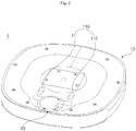
- FIG. 1 is a perspective view illustrating a robot cleaner according to an embodiment of the present invention.
- FIG. 2 is a view illustrating an undersurface of the robot cleaner of FIG. 1 .
- FIG 3 is an exploded perspective view illustrating the robot cleaner of FIG. 1 .
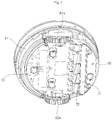
- FIG. 4 is a view illustrating a location sensor of FIG. 3 .
- FIG. 5 is an exploded perspective view illustrating the location sensor of FIG. 4 .
- FIG. 6 is a view illustrating a retracted location of the location sensor and FIG. 6B is a view illustrating a protracted location of the location sensor, respectively.
- FIG. 7 is a view illustrating a control relationship among main units of a robot cleaner according to an embodiment of the present invention.
- a robot cleaner 1 may include a main body 10, a location sensor 20, a rotation drive unit 40, an elevation drive unit 50, and a controller 90.
- the main body 10 may travel around an area (hereinafter, referred to as "cleaning area") to be cleaned to suction foreign substances such as dust or garbage through a suctioning unit 70.
- cleaning area an area to be cleaned to suction foreign substances such as dust or garbage through a suctioning unit 70.
- the suctioning unit 70 may include a suctioning fan 72 disposed in the main body 10 to generate a suctioning force and a suctioning inlet 71 for suctioning air flow generated by the rotation of the suctioning fan 72. Also, the suctioning unit 70 may further include a filter (not shown) for filtering foreign substances among air suctioned through the suctioning inlet 71 and a foreign substance container (not shown) for collecting foreign substances filtered by the filter.
- the robot cleaner 1 may further include a traveling drive unit 60 for driving the left wheel 61a and the right wheel 62a, and may further include a left wheel drive unit 61 for driving the left wheel and a right wheel drive unit 62 (reference number 62 of FIG. 3 indicates the right wheel drive unit disposed at the opposite side of the left wheel drive unit 61) for driving the right wheel 62a. Since the operation of the left wheel drive unit 61 and the right wheel drive unit 62 is independently controlled by the controller 90, the main body 10 may move forward and backward or turn around.
- the controller 90 may control the rotational speed of the left wheel drive unit 61 and the right wheel drive unit 62 to differ from each other.
- the motion of the main body 10 by the control of the controller 90 enables avoidance or turning with respect to obstacles.
- the robot cleaner 1 may further include at least one auxiliary wheel 13 to stably support the main body 10.
- the main body 10 may include a lower body 11 that houses the rotation drive unit 40, the elevation drive unit 50, and the traveling drive unit 60, and an upper body 12 that covers the lower body 11.
- the location sensor 20 may retract and protract through an elevation aperture 12a formed in the upper body 12.
- a transparent member 32 may be disposed on a path along which light emitted from a light-transmitting unit 21 of the location sensor 20 or light received in a light-receiving unit 23 travels.
- the transparent member 32 may be fixed on the main body 10.
- the main body 10 may have an opening at the front side thereof.
- the transparent member 32 may be fixed by a transparent member frame 31 installed in the opening.
- the transparent member frame 31 may include a first frame member 31a and a second frame member 31b.
- the first frame member 31a and the second frame member 31b may have a coupling groove which the transparent member 32 is inserted into, respectively.
- the transparent member frame 31 may have a receiving groove 34 concaved toward the transparent member 32 to surround the location sensor 20.
- the receiving groove 34 may be formed in at least one of the first frame member 31a and the second frame member 31b.
- FIG. 6A illustrates the location sensor 20 that is at a retracted location.
- Light emitted from the light-transmitting unit 21 may travel toward the front side of the main body 10 through the transparent member 32 described later, and light reflected or scattered by obstacles may travel toward the transparent member 32 to be received by the light-receiving unit 22.
- FIG. 6B illustrates the location sensor 20 that is at a protracted location.
- the location sensor 20 may upwardly protrude from the main body 10 through the elevation aperture 12a, such that the light-transmitting unit 21 and the light-receiving unit 22 may be located at the upper side of the main body 10.
- the location sensor 20 may sense the location or distance of obstacles by emitting light to the obstacles.
- the location sensor 20 may be rotatably and vertically movably disposed in the main body 10.
- the location sensor 20 may further include a base 23 in addition to the light-transmitting unit 21 and the light-receiving unit 22.
- the light-transmitting unit 21 may include a light source that emits light and a collimate lens that refracts light (L1 of FIGS. 4 and 5 ) emitted from the light source so as to travel in parallel.
- the light source may include a light emitting element, e.g., an infrared or visible ray light emitting diode (LED) that emits infrared rays or visible rays.
- the light source may be a light emitting element that emits a laser beam.
- a laser diode (LD) 210 will be exemplified as the light source.
- the light source 210 using a laser beam may enable accurate measurement compared to other lights due to the monochromatic, directionality, and collimation characteristics of a laser beam.
- infrared rays or visible rays may vary in measurement accuracy according to the ambient environmental factors such as color or texture of a subject.
- the light-receiving unit 22 may include an image sensor 220 on which a spot of light (L2 of FIGS. 4 and 5 ) reflected or scattered by obstacles is formed.
- the image sensor 220 may be an assembly of a plurality of unit pixels that are arranged in a matrix form of m X n.
- the unit pixel may be implemented with various kinds of light receiving elements such as cadmium sulfide cell (CdS), photo diode, photo transistor, solar cell, and photoelectric tube. These light receiving elements may convert optical signals into electric signals.
- CMOS complementary metal-oxide semiconductor
- the light receiving unit 22 may include a light receiving lens 230. Light reflected or scattered by obstacles may travel through the light receiving lens 230 to form an image on the image sensor 220.
- the light receiving lens 230 may include a plurality of lenses.
- the base 23 may support the light transmitting unit 21 and the light receiving unit 22, and may be rotatably and vertically movably disposed at the main body 10.
- the light transmitting unit 21 and the image sensor 220 may be disposed at certain interval from each other on the base 23.
- the rotation drive unit 40 which rotates the base 23, may include a motor 41 for providing a torque and power transmission members such as belt and/or gear which deliver the torque of the motor 41 to rotate the base 23.
- the power transmission members are illustrated as including a pulley 42 connected to a shaft of the motor 41 and a belt 43 delivering the torque of the motor 41 between the pulley 42 and the base 23, but the present invention is not limited thereto.
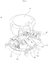
- a supporter 25 may be further provided to support the location sensor 20.
- the base 23 may be rotatably supported by the supporter 25.
- the supporter 25 may be fixed on the lower body 11 by coupling members such as screw or bolt.
- the elevation drive unit 50 described later may allow the base 23 to retract and protract from the main body 10, but the present invention is not limited thereto.
- the supporter 25 may be vertically movable with respect to the lower body 11 by the elevation drive unit 50.
- a base cover 24 may be coupled to the base 23, and may rotate together with the base 23.
- a light transmitting passage 21a through which light emitted from the light transmitting unit 21 passes and a light receiving passage 22a through which light received in the light receiving unit 22 passes may be formed between the base cover 24 and the base 23.
- the elevation drive unit 50 may allow the location sensor 20 to retract and protract from the main body 10.
- the elevation drive unit 50 may include a linear or rotational motor (not shown).
- a power transmission unit may be provided to perform power transmission or conversion between the elevation drive unit 50 and the location sensor 20.
- the power transmission unit may be implemented with members such as gear, pulley, and/or belt.
- the power transmission unit may include a drive pinion rotated by the motor, and a rack is fixedly disposed in the base 23 to engage with the drive pinion.
- the controller 90 may control the operation of the rotation drive unit 40 and the elevation drive unit 50. According to embodiments, the controller 90 may perform the control of components such as the light source 210, the image sensor 220, and the traveling drive unit 60, and/or other components constituting the robot cleaner 1.
- the controller 90 may include a microprocessor that processes electric signals inputted from the image sensor 220.
- the controller 90 may include only one controller.
- the robot cleaner 1 may include a plurality of controllers for controlling each component. In this case, the controller 90 may be defined as a part or all of the plurality of controllers. The controllers need only to be electrically connected to each other in terms of transmission/reception of signals. The spatial disposition between the controllers may be irrelevant to the definition of the controller 90.
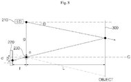
- FIG. 8 is a view illustrating a principle of measuring a distance from an object.
- the basic principle of sensing the location of an object using the location sensor 20 may be based on a triangulation method.
- Light emitted from the light source 210 may have a certain angle ⁇ with respect to the main axis C that is orthogonal from the center surface of the light receiving lens 230.
- the angle ⁇ may be closely related with the accuracy of the distance measurement from the object. If the angle ⁇ is too small, it may be difficult to measure a distance from an object at a close range. On the other hand, if the angle ⁇ is too large, it may be difficult to measure a distance from an object at a long range. Accordingly, the angle ⁇ needs to have an appropriate value such that an object located at a range from about 0.1 m to about 4 m can be measured.
- the image sensor 220 may be disposed such that it is spaced from the light source 210.
- the light receiving lens 230 may be disposed between the image sensor 220 and the object or obstacle 300.
- the object distance L can be expressed as Equation 1 below.
- f is a focal length
- g is an interval between the light source 210 and the light receiving lens 230
- ⁇ is an angle between light emitted from the light source 210 and the main axis C of the light receiving lens 230
- p is a length a center O of the image sensor 220 to a spot of the image sensor 220 where light reflected or scattered by the object is detected.
- FIGS. 9A, 9B, and 9C are views illustrating three exemplary spot distributions formed on an image sensor of a location sensor.
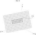
- FIG. 10 is a view illustrating three-dimensional mapping based on location information acquired by the image sensor of FIGS. 9A, 9B, and 9C .
- the row corresponds to the rotational angle ⁇ of the base 23, and the column corresponds to the rise height H of the elevation drive unit 50.
- the respective pixels of the image sensor 220 indicate the obstacle distribution situation in the cleaning area.
- the location information of the respective pixels constituting the image sensor 220 may include distances from obstacles corresponding to each pixel as well as coordinates on the matrix. Accordingly, the three-dimensional location information of the obstacles corresponding to the respective pixels can be acquired by the location information of the respective pixels.
- each column of the spot coordinates in the matrix may correspond to the rotational angle ⁇ of the base 23.
- the rotation of the base 23 may be considered as turning within a certain range, or may be considered as 360 degrees or more rotation.
- the rotation drive unit 40 may continuously rotate the base 23 in one direction.
- the location information used for the mapping of the cleaning area may be obtained from a section corresponding to the profile of the transparent member 32, for example, section between 0 degree to 180 degrees.
- the controller 90 may control the rotation drive unit 40 such that the base 23 rotates at least 360 degrees in one embodiment.
- the obstacle situation of the 360 degree full range around the robot cleaner 1 can be scanned.
- the height of the base 23 may vary with the operation of the elevation drive unit 50, that is, the elevation drive unit may operate in several heights, and the base 23 may be rotated by the rotation drive unit 40 at each height. Accordingly, each row of the spot coordinates on the matrix may correspond to the height H of the base 23 at which the elevation drive unit 50 has elevated the base 23.
- spots are distributed over three rows in FIG. 9A .
- the spots in each row may be spots formed on the image sensor 220 at three different heights at which the base 23 is elevated by the operation of the elevation drive unit 50.
- FIG. 9A shows the arrangement of the spots when obstacles exist at the upper and lower part within the cleaning area.
- FIGS. 9B and 9C show a scan result of the cleaning area when the base 23 is allowed to retract and/or protract by the operation of the elevation drive unit 50 and then is rotated by the rotation drive unit 40.
- FIG. 9B shows a situation where obstacles are mainly distributed at the lower part in the cleaning area compared to FIG. 9A
- FIG. 9C shows a situation where obstacles are mainly distributed at the upper part in the cleaning area compared to FIG. 9A .
- the location sensor 20 can scan the cleaning area while elevating and rotating with respect to the main body 10.
- the coordinates of the spots formed on the image sensor 220 may correspond to the retracted & protracted height H of the base 23 in row, and may correspond to the rotational angle ⁇ of the base 23 in column.
- the controller 90 can three-dimensionally map the obstacle distribution situation in the cleaning area from the coordinates of the spots and the distances from the obstacles corresponding to each spot in accordance with Equation (1) described above.
- the height H of an obstacle, rotational angle ⁇ , and the object distance L corresponding to each spot will be referred to as location information.
- the controller 90 can map the obstacle distribution situation in the cleaning area, based on the location information.
- FIG. 10 shows mapping of the coordinate [ ⁇ , ⁇ 2, L] of each pixel on X-Y-Z space, and three-dimensionally shows the obstacle situation in the cleaning area.
- the location on Z-axis is assigned according to the object distance L corresponding to each pixel, it can be shown that X-Y plane where pixels are located is distorted in the Z-axis direction.
- the base 23 may vertically move according to the operation of the elevation drive unit 50.
- the condition where the base 23 retracts to is defined as a first location
- the condition where the base 23 protracts to is defined as a second location.
- the location of the base 23 is not necessarily limited to the two locations.
- the operation of the elevation drive unit 50 may be controlled such that location of the base 23 can be subdivided between the lowest retracted location and the highest protracted location, enabling the sensing of obstacles at each location between the lowest retracted location and the highest protracted location.
- FIGS. 9A, 9B, 9C , and 10 show the distribution of the spot when ranges covering three or more rows are scanned. This means that the obstacles are sensed at three or more locations where the heights of the base 23 are different from each other.
- the base 23 may be housed in the main body 10 at a first location.
- light emitted from the light source 210 may travel toward obstacles through the front side of the main body 10.
- the main body 10 may have an opening at the front side thereof to allow light emitted from the light source 210 to pass through.
- the opening may be provided with a transparent member 32 that passes the light.
- Light emitted to obstacle at the first location may travel in a substantially horizontal direction.
- the base 23 When the base 23 is at the second location, light emitted from the light source 210 may travel toward obstacles from the upper side of the main body 10.
- the traveling direction of light may be substantially parallel to the traveling direction at the first location. Accordingly, since obstacles sensed by light emitted when the base 23 is at the second location are at higher locations than those sensed at the first location, three-dimensional obstacle information for the cleaning area may be obtained.
- the controller 90 may perform at least one of a first obstacle sensing control of rotating the base 23 by controlling the rotation drive unit 40 at the first location and a second obstacle sensing control of rotating the base 23 by controlling the rotation drive unit 40 after raising the base 23 to the second location by controlling the elevation drive unit 50.
- the first obstacle sensing control may be to sense the location of obstacles distributed at a relatively lower location in the cleaning area
- the second obstacle sensing control may be to sense the location of obstacles distributed at a relatively higher location than the first obstacle sensing control.
- the location information acquired by the first obstacle sensing control and the location information acquired by the second obstacle sensing control may include information regarding the same obstacle on a plane.
- the location information acquired by the second obstacle sensing control may indicate that the obstacle exists at a certain location on the plane while the location information acquired by the first obstacle sensing control indicates that the obstacle does not exist at a certain location on the plane.
- this may be a case where a certain space (not sensed at the first location) exists under a bed frame (obstacle sensed at the second location) supporting a bed.
- the controller 90 may control the traveling driving unit 60 based on the obstacle situation in the cleaning area, i.e., ambient obstacle situation acquired by the mapping or the location information acquired by the image sensor 220.
- FIG. 9A illustrates the height of an obstacle higher than a certain height.
- the controller 90 may control the traveling drive unit 60 so as to avoid the obstacle (hereinafter, referred to as 'avoidance traveling'), which corresponds to a case where the height of the obstacle is too high for the robot cleaner 1 to cross the obstacle.
- FIG. 9B illustrates the height of an obstacle lower than a certain height.
- the controller 90 may control the traveling drive unit 60 so as to cross the obstacle (hereinafter, referred to as 'cross traveling').
- FIG. 9C assumes a situation where an obstacle does not exist at a lower part of the space to be cleaned even though an obstacle is sensed at an upper part thereof (e.g., bed).
- the controller 90 may control the traveling drive unit 60 such that the robot cleaner 1 passes the space when the space under the obstacle is sufficiently large for the main body 10 to pass (hereinafter, referred to as 'passing traveling').
- the controller 90 may control the traveling drive unit 60 to perform the avoidance traveling.
- the controller 90 may control the elevation drive unit 50 such that the base 23 is housed in the main body to avoid the interference by the upper obstacle.
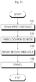
- FIG. 11 is a flowchart illustrating a method of controlling a robot cleaner according to an embodiment of the present invention.
- the controller 90 may sense the location of obstacles by controlling the rotation drive unit 40 such that the base 23 is rotated while being at the first location (first obstacle sensing; S11). If an obstacle is sensed upon first obstacle sensing, the controller 90 may control the elevation drive unit 50 such that the base 23 rises to the second location (rising of location sensor; S12), and may re-sense the location of the obstacle by controlling the rotation drive unit 40 such that the base 23 is rotated at the second location (second obstacle sensing; S13). Thereafter, the controller 90 may map the obstacle situation in the cleaning area based on the obstacle sensing results at the first and second locations, and may perform traveling of the robot cleaner 1 based on the mapping result (traveling; S14).
- the traveling in operation S14 may include avoidance traveling, overcoming traveling, and passing traveling according to the obstacle situation.
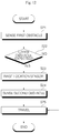
- FIG. 12 is a flowchart illustrating a method of controlling a robot cleaner according to another embodiment of the present invention.
- FIGS. 13A and 13B are views illustrating two exemplary obstacle situations sensed within a cleaning area.
- the controller 90 may sense the location of obstacles by controlling the rotation drive unit 40 such that the base 23 is rotated while being at the first location (first obstacle sensing; S21).
- FIG. 9A and 9B Two situations of FIG. 9A and 9B can be assumed as examples in which an obstacle exists within a range sensed by the first obstacle sensing.
- FIG. 13A illustrates a case where four or more obstacles PI, P2, P3 and P4 are sensed to be distributed in a certain range S through an ambient obstacle situation mapped by the first obstacle sensing. This may mainly occur in a case where furniture such as desk, chair, table, and bed supported by four or legs exist within the cleaning area. This sensing result may correspond to a case where an upper obstacle (e.g., bed frame supporting the mattress) is expected to exist ('Yes' of S22).
- the controller 90 may control the elevation drive unit 50 such that the base 23 rises to the second location (raising location sensor; S23), and then may control the rotation drive unit 40 such that the base 23 is rotated at the second location to re-sense the location of the obstacle (second obstacle sensing; S24).
- the controller 90 may map the obstacle situation in the cleaning area based on the obstacle sensing results at the first and second locations and may perform traveling of the robot cleaner 1 based on the mapping result (traveling; S25).
- the traveling in operation S25 may include avoidance traveling, cross traveling, and passing traveling according to the obstacle situation.
- the controller 90 may control the traveling drive unit 60 according to the height of a section W3 between the two straight line components W1 and W2.
- FIG. 13B corresponds to a case where a door between walls is opened.
- the two straight line components W1 and W2 correspond to the walls, and the section W3 between the two straight line components W1 and W2 corresponds to a threshold.
- the controller 90 may control the traveling drive unit 60 according to the height of the threshold.
- the controller 90 may control the traveling drive unit 60 so as to perform the passing traveling or the cross traveling, and otherwise, the controller 90 may control the traveling drive unit 60 so as to perform the avoidance traveling.
- the robot cleaner 1 may further include an upward distance sensor 110 that is disposed on the upper part of the main body 10, and may emit light upward from the upper side of the main body 10 to measure a distance from an obstacle.
- an upward distance sensor 110 that is disposed on the upper part of the main body 10, and may emit light upward from the upper side of the main body 10 to measure a distance from an obstacle.
- the upward distance sensor 110 may include a light-transmitting unit 111 disposed on the upper part of the main body 10 at a certain interval and a light-receiving unit 112 to receive light reflected or scattered by obstacles. As described with reference to FIG. 8 , the upward distance sensor 110 may be implemented with a sensor measuring a distance from an object using a triangulation method or a sensor measuring a distance from an object according to the amount of light received on the light-receiving unit 112.
- a method of controlling the robot cleaner 1 in a case where an obstacle is sensed to exist within a certain distance over the main body 10 when the location sensor 20 protrudes from the main body 10 by a certain height This assumption may consider a case where the robot cleaner 1 passes under a bed.
- the controller 50 may check an extra space under the bed based on the distance sensed by the upward distance sensor 110, and thus may control the height of the location sensor 20 by the control of the elevation drive unit 50.
- the controller 50 may control the elevation drive unit 50 such that the location sensor further rises, and may perform obstacle sensing while rotating the base 23 by again controlling the rotation drive unit 40 at a height where the location sensor 20 is placed.
- the maximum rising height of the location sensor 20 may be within the measurement distance sensed by the upward distance sensor 110.
- FIG. 14 is a flowchart illustrating a method of controlling a robot cleaner according to still another embodiment of the present invention.
- the robot cleaner 1 may sense and map the obstacle situation within the cleaning area before the traveling of the robot cleaner 1, and then may perform traveling based thereon.
- the sensing and mapping of the obstacle situation may be first performed when the location sensor 20 upwardly protrudes from the main body 10 (see FIG. 6B ).
- the height of the location sensor 20 may be adjusted according to the ambient obstacle situation that is sensed.
- controller 90 may control the elevation drive unit 50 such that the location sensor 20 rises to a location (hereinafter, referred to as 'first location') where the main body 10 upwardly protrudes (S31).
- the controller 90 may rotate the rotation drive unit 40 such that the location sensor 20 senses the location of obstacles while rotating at the first location.
- the base 23 may rotate 360 degrees or more, scanning the whole region around the robot cleaner 1 in terms of angle (first obstacle sensing; S32).
- the rising height of the location sensor 20 may vary, and the ambient obstacle situation may be sensed by the rotation of the base 23 at each height.
- three-dimensional obstacle sensing can be performed in the vertical direction of the cleaning area (see FIGS. 9A, 9B, 9C , and 10 ).
- the controller 90 may allow the location sensor 20 to be housed at the second location in the main body 10 by controlling the elevation drive unit 50 (S34).
- the controller 90 may perform the second obstacle sensing by controlling the rotation drive unit 40 such that the location sensor 20 rotates at the second location (S35).
- the location sensor 20 may scan a limited range with respect to an area corresponding to the transparent member 32 or the opening at the front side of the main body 10, but the present invention is not limited thereto.
- the location sensor 20 may scan the whole region around the robot cleaner 1 while rotating in place through the driving control of the left wheel 61a and the right wheel 62a upon second obstacle sensing.
- the controller 90 may control the traveling of the robot cleaner 1 (S36). That is, the controller 90 may control the traveling of the robot cleaner 1 based on the obstacle situation obtained from the first obstacle sensing (S32) in which the obstacle situation for the whole region around the robot cleaner 1 in terms of angle can be sensed, and in this case, when an obstacle is sensed by the first obstacle sensing (S32), the second obstacle sensing (S35) may be performed to again check whether or not there is a space for the robot cleaner 1 to pass under the sensed obstacle.
- the controller 90 may control the robot cleaner 1 to pass under the obstacle or clean the area under the obstacle.
- the robot cleaner according to the embodiment of the present invention has an effect of accurately scanning the obstacle situation in the cleaning area.
- the obstacle distribution situation in the cleaning area can be three-dimensionally scanned, and based thereon, appropriate avoidance or overcoming traveling for obstacles can be performed.
- the robot cleaner according to the embodiment of the present invention has an effect of accurately scanning the obstacle distribution situation in the cleaning area, as well as the distance from the obstacles.
- a method of controlling a robot cleaner according to an embodiment of the present invention can also be embodied as computer readable codes on a computer readable recording medium.
- the computer readable recording medium is any data storage device that can store data which can be thereafter read by a computer system. Examples of the computer readable recording medium include read-only memory (ROM), random-access memory (RAM), CD-ROMs, magnetic tapes, floppy disks, optical data storage devices, and carrier waves such as data transmission through the Internet.
- the computer readable recording medium can also be distributed over network coupled computer systems so that the computer readable code is stored and executed in a distributed fashion.
Landscapes
- Engineering & Computer Science (AREA)
- Physics & Mathematics (AREA)
- Mechanical Engineering (AREA)
- Robotics (AREA)
- General Physics & Mathematics (AREA)
- Radar, Positioning & Navigation (AREA)
- Optics & Photonics (AREA)
- Electromagnetism (AREA)
- Aviation & Aerospace Engineering (AREA)
- Remote Sensing (AREA)
- Automation & Control Theory (AREA)
- Human Computer Interaction (AREA)
- Control Of Position, Course, Altitude, Or Attitude Of Moving Bodies (AREA)
- Electric Vacuum Cleaner (AREA)
- Nozzles For Electric Vacuum Cleaners (AREA)
Claims (13)
- Robot nettoyeur comportant :un corps principal (10) ;une unité de transmission de lumière (21) qui émet de la lumière ;un capteur d'image (220) qui détecte la lumière réfléchie ou diffusée par un obstacle provenant de la lumière émise à partir de l'unité de transmission de lumière (21) ;caractérisé parune base (23) supportant l'unité de transmission de lumière (21) et le capteur d'image (220) et disposée de façon à pouvoir tourner et se déplacer verticalement dans le corps principal (10) ;une unité d'entraînement en rotation (40) qui fait tourner la base (23) ; etune unité d'entraînement en élévation (50) qui permet à la base (23) de se rétracter et de s'étendre à partir du corps principal (10).
- Robot nettoyeur selon la revendication 1, dans lequel lorsque l'unité d'entraînement en élévation (50) dispose la base (23) à un première emplacement, l'unité de transmission de lumière (21) émet de la lumière vers l'obstacle à travers un côté avant du corps principal (10), et lorsque l'unité d'entraînement en élévation (50) dispose la base (23) à un second emplacement, l'unité de transmission de lumière (21) émet de la lumière vers l'obstacle depuis un côté supérieur du corps principal (10).
- Robot nettoyeur selon la revendication 2, comportant en outre une commande (90) pour commander au moins une unité parmi l'unité d'entraînement en rotation (40) et l'unité d'entraînement en élévation (50),
dans lequel la commande (90) exécute au moins une commande parmi une première commande de détection d'obstacle en commandant l'unité d'entraînement en rotation (40) de manière à faire tourner la base (23) au premier emplacement, et une seconde commande de détection d'obstacle en commandant l'unité d'entraînement en élévation (50) pour lever la base (23) jusqu'au second emplacement et en commandant l'unité d'entraînement en rotation (40) de manière à faire tourner la base. - Robot nettoyeur selon la revendication 3, dans lequel la commande (90) commande l'unité d'entraînement en élévation (50) pour rétracter la base de telle sorte que la base (23) est reçue dans le corps principal (10) lorsque l'obstacle est détecté par la commande (90) via la seconde commande de détection d'obstacle.
- Robot nettoyeur selon la revendication 3, comportant en outre une unité d'entraînement en déplacement (60) pour permettre au corps principal (10) de se déplacer,
dans lequel après l'exécution de la première commande de détection d'obstacle et de la seconde commande de détection d'obstacle, la commande (90) peut commander l'unité d'entraînement en déplacement (60) de telle sorte que le corps principal (10) est capable de se déplacer. - Robot nettoyeur selon la revendication 5, dans lequel la commande (90) cartographie de manière tridimensionnelle une situation d'obstacle à l'intérieur d'une zone à nettoyer sur la base d'un angle de rotation de la base (23) mise en rotation par l'unité d'entraînement en rotation (40), d'une hauteur levée par l'unité d'entraînement en élévation (50), et d'une distance par rapport à l'obstacle, obtenus à partir d'un emplacement d'un spot formé sur le capteur d'image (220).
- Robot nettoyeur selon la revendication 6, dans lequel la commande (90) commande l'unité d'entraînement en déplacement (60) de telle sorte que le corps principal (10) évite, croise ou franchit l'obstacle, sur la base de la situation d'obstacle cartographiée.
- Robot nettoyeur selon la revendication 6, dans lequel la commande (90) exécute la seconde commande de détection d'obstacle lorsqu'une pluralité d'obstacles est détectée à l'intérieur une zone détectée par la commande (90) via la première commande de détection d'obstacle.
- Robot nettoyeur selon la revendication 6, dans lequel lorsque deux composants en ligne droite espacés l'un de l'autre à un certain intervalle sur la même ligne sont détectés par la commande (90) via la première commande de détection d'obstacle, la commande (90) commande l'unité d'entraînement en déplacement (60) de manière à se déplacer en évitant, en croisant ou en passant entre les deux composants en ligne droite en fonction d'une hauteur d'une section entre les deux composants de ligne droite.
- Robot nettoyeur selon la revendication 1, dans lequel l'unité d'entraînement en rotation (40) fait tourner la base (23) sur une certaine plage angulaire, à 360 degrés ou à plus de 360 degrés.
- Robot nettoyeur selon la revendication 1, dans lequel l'unité de transmission de lumière (21) comporte une diode laser (210) émettant un faisceau laser.
- Robot nettoyeur selon la revendication 1, dans lequel le corps principal (10) est pourvu d'un élément transparent (32) pour laisser passer la lumière émise à partir de l'unité de transmission de lumière (21) lorsque l'unité d'entraînement en élévation (50) rétracte la base (23) dans le corps principal (10).
- Robot nettoyeur selon la revendication 1, comportant en outre une lentille de réception de lumière, dans lequel la lentille de réception de lumière (230) est disposée entre le capteur d'image (220) et l'obstacle, et lorsqu'une distance entre l'obstacle et la lentille de réception de lumière (230) est définie comme distance L, la distance L est déterminée par :

Applications Claiming Priority (1)
| Application Number | Priority Date | Filing Date | Title |
|---|---|---|---|
| KR1020130023564A KR101450569B1 (ko) | 2013-03-05 | 2013-03-05 | 로봇 청소기 |
Publications (3)
| Publication Number | Publication Date |
|---|---|
| EP2774523A2 EP2774523A2 (fr) | 2014-09-10 |
| EP2774523A3 EP2774523A3 (fr) | 2014-12-24 |
| EP2774523B1 true EP2774523B1 (fr) | 2020-01-08 |
Family
ID=49920204
Family Applications (1)
| Application Number | Title | Priority Date | Filing Date |
|---|---|---|---|
| EP14150867.1A Active EP2774523B1 (fr) | 2013-03-05 | 2014-01-13 | Robot nettoyeur |
Country Status (4)
| Country | Link |
|---|---|
| US (1) | US9283670B2 (fr) |
| EP (1) | EP2774523B1 (fr) |
| KR (1) | KR101450569B1 (fr) |
| CN (1) | CN104027041B (fr) |
Cited By (1)
| Publication number | Priority date | Publication date | Assignee | Title |
|---|---|---|---|---|
| WO2023180031A1 (fr) * | 2022-03-21 | 2023-09-28 | BSH Hausgeräte GmbH | Robot nettoyeur |
Families Citing this family (65)
| Publication number | Priority date | Publication date | Assignee | Title |
|---|---|---|---|---|
| KR20160048492A (ko) * | 2014-10-24 | 2016-05-04 | 엘지전자 주식회사 | 로봇 청소기 및 이의 제어 방법 |
| KR102328252B1 (ko) * | 2015-02-13 | 2021-11-19 | 삼성전자주식회사 | 청소 로봇 및 그 제어방법 |
| CN106137057B (zh) * | 2015-04-15 | 2018-10-19 | 小米科技有限责任公司 | 清洁机器人及机器人防碰撞方法 |
| US9746854B2 (en) * | 2015-04-24 | 2017-08-29 | Autonomous Solutions, Inc. | System and method for controlling a vehicle |
| US10667664B2 (en) * | 2015-04-24 | 2020-06-02 | Avidbots Corp. | Apparatus and methods for semi-autonomous cleaning of surfaces |
| DE102015106536B4 (de) * | 2015-04-28 | 2016-11-10 | Vorwerk & Co. Interholding Gmbh | Haushaltsroboter und Verfahren zum Betreiben eines Haushaltsroboters |
| DE102015109775B3 (de) | 2015-06-18 | 2016-09-22 | RobArt GmbH | Optischer Triangulationssensor zur Entfernungsmessung |
| CN106323230B (zh) * | 2015-06-30 | 2019-05-14 | 芋头科技(杭州)有限公司 | 一种障碍物识别装置及障碍物识别方法 |
| CN106406300B (zh) * | 2015-07-28 | 2020-04-07 | 智棋科技有限公司 | 清洁装置及其控制方法 |
| DE102015114883A1 (de) | 2015-09-04 | 2017-03-09 | RobArt GmbH | Identifizierung und Lokalisierung einer Basisstation eines autonomen mobilen Roboters |
| CN106502241A (zh) * | 2015-09-07 | 2017-03-15 | 北醒(北京)光子科技有限公司 | 一种扫地机器人智能避障及定位系统 |
| CN105380573B (zh) * | 2015-10-28 | 2017-12-05 | 珠海格力电器股份有限公司 | 用于智能吸尘器寻找充电设备的装置、方法及智能吸尘器 |
| DE102015119501A1 (de) | 2015-11-11 | 2017-05-11 | RobArt GmbH | Unterteilung von Karten für die Roboternavigation |
| DE102015119865B4 (de) | 2015-11-17 | 2023-12-21 | RobArt GmbH | Robotergestützte Bearbeitung einer Oberfläche mittels eines Roboters |
| CN105372669A (zh) * | 2015-12-04 | 2016-03-02 | 大族激光科技产业集团股份有限公司 | 一种激光测距装置 |
| DE102015121666B3 (de) | 2015-12-11 | 2017-05-24 | RobArt GmbH | Fernsteuerung eines mobilen, autonomen Roboters |
| DE102016102644A1 (de) | 2016-02-15 | 2017-08-17 | RobArt GmbH | Verfahren zur Steuerung eines autonomen mobilen Roboters |
| CN105982611A (zh) * | 2016-04-14 | 2016-10-05 | 北京小米移动软件有限公司 | 自主清洁设备 |
| WO2018024897A1 (fr) | 2016-08-05 | 2018-02-08 | RobArt GmbH | Procédé de commande d'un robot mobile autonome |
| AU2017316091B2 (en) * | 2016-08-25 | 2020-10-29 | Lg Electronics Inc. | Mobile robot and control method therefor |
| KR101952414B1 (ko) * | 2016-10-25 | 2019-02-26 | 엘지전자 주식회사 | 청소기 및 그 제어방법 |
| US10962647B2 (en) | 2016-11-30 | 2021-03-30 | Yujin Robot Co., Ltd. | Lidar apparatus based on time of flight and moving object |
| KR102035018B1 (ko) * | 2016-12-06 | 2019-10-22 | 주식회사 유진로봇 | 청소 기능 제어 장치 및 이를 구비하는 청소 로봇 |
| TWI626427B (zh) * | 2016-12-28 | 2018-06-11 | 合盈光電科技股份有限公司 | 適用於機器人之監測系統 |
| WO2018132632A1 (fr) | 2017-01-13 | 2018-07-19 | Diversey, Inc. | Balayage tridimensionnel utilisant des capteurs de distance plans fixes |
| CN106667380B (zh) * | 2017-01-18 | 2022-06-10 | 浙江汉脑数码科技有限公司 | 一种多功能智能扫地机器人 |
| WO2018143620A2 (fr) * | 2017-02-03 | 2018-08-09 | Samsung Electronics Co., Ltd. | Robot nettoyeur et son procédé de commande |
| JP2020509500A (ja) | 2017-03-02 | 2020-03-26 | ロブアート ゲーエムベーハーROBART GmbH | 自律移動ロボットの制御方法 |
| KR101984101B1 (ko) * | 2017-03-06 | 2019-05-30 | 엘지전자 주식회사 | 청소기 및 그 제어방법 |
| WO2018165522A1 (fr) * | 2017-03-10 | 2018-09-13 | Diversey, Inc. | Capteurs de proximité à hauteur variable sur des véhicules autonomes |
| DE102017109219A1 (de) | 2017-04-28 | 2018-10-31 | RobArt GmbH | Verfahren für die Roboternavigation |
| US11579298B2 (en) | 2017-09-20 | 2023-02-14 | Yujin Robot Co., Ltd. | Hybrid sensor and compact Lidar sensor |
| JP6655804B2 (ja) * | 2017-11-10 | 2020-02-26 | パナソニックIpマネジメント株式会社 | 移動ロボット、及び、移動ロボットの制御方法 |
| CN107997693A (zh) * | 2017-12-20 | 2018-05-08 | 苏州燕云网络技术有限公司 | 扫地机控制方法及扫地机 |
| CN108030447B (zh) * | 2017-12-29 | 2023-10-31 | 美的集团电子商务有限公司 | 扫地机器人及其建立地图的方法和控制方法 |
| US11009882B2 (en) * | 2018-01-12 | 2021-05-18 | Pixart Imaging Inc. | Method, system for obstacle detection and a sensor subsystem |
| WO2019195483A1 (fr) | 2018-04-03 | 2019-10-10 | Sharkninja Operating Llc | Système de capteurs de temps de vol destiné à une navigation robotisée et procédés de localisation mettant en œuvre un tel système |
| CN110353571A (zh) * | 2018-04-11 | 2019-10-22 | 雅视特科技(杭州)有限公司 | 一种多功能扫地机器人 |
| US11874399B2 (en) | 2018-05-16 | 2024-01-16 | Yujin Robot Co., Ltd. | 3D scanning LIDAR sensor |
| DE102018117191A1 (de) | 2018-07-17 | 2020-01-23 | Miele & Cie. Kg | Saugroboter, Ladestation für einen Saugroboter und Verfahren zum Betreiben eines Saugroboters |
| DE102018117192A1 (de) | 2018-07-17 | 2020-01-23 | Miele & Cie. Kg | Saugroboter, Ladestation für einen Saugroboter und Verfahren zum Betreiben eines Saugroboters |
| JP2020010982A (ja) * | 2018-07-20 | 2020-01-23 | パナソニックIpマネジメント株式会社 | 自走式掃除機 |
| GB2576494B (en) | 2018-08-06 | 2022-03-23 | Dyson Technology Ltd | A mobile robot and method of controlling thereof |
| KR102203457B1 (ko) * | 2018-08-31 | 2021-01-15 | (주)디알젬 | 엑스선 촬영장치 및 그 제어방법 |
| KR102521942B1 (ko) * | 2018-09-27 | 2023-04-14 | 엘지전자 주식회사 | 레이저 다이오드 구동회로 및 그것의 동작방법과, 이를 포함하는 로봇 청소기 |
| US11141863B2 (en) * | 2018-10-11 | 2021-10-12 | Pixart Imaging Inc. | Cleaning robot capable of detecting 2D depth information and operating method thereof |
| CN109480698A (zh) * | 2018-11-23 | 2019-03-19 | 广州富港万嘉智能科技有限公司 | 餐桌清扫机器人 |
| KR102117868B1 (ko) * | 2019-02-28 | 2020-06-04 | 한국생산기술연구원 | 높이 조절이 가능한 라이다 구동부 및 이를 이용한 로봇 청소기 |
| TWI683197B (zh) | 2019-03-19 | 2020-01-21 | 東元電機股份有限公司 | 移動平台圖資校正系統 |
| KR102791416B1 (ko) | 2019-06-04 | 2025-04-08 | 삼성전자주식회사 | 로봇청소기 |
| JP7369592B2 (ja) * | 2019-10-30 | 2023-10-26 | 株式会社マキタ | 検出装置及びロボット集塵機 |
| KR102290612B1 (ko) * | 2019-11-21 | 2021-08-20 | 한국생산기술연구원 | 로봇청소기의 라이다 회전장치 및 이의 회전각도 보정방법 |
| CN111158369B (zh) * | 2019-12-31 | 2025-07-01 | 佛山市云米电器科技有限公司 | 一种扫地机器人及其检测控制清扫的方法 |
| US12157233B2 (en) * | 2020-04-17 | 2024-12-03 | Brain Corporation | Systems and methods for quantitatively measuring wheel slippage in differential drive robots |
| KR20220019930A (ko) * | 2020-08-11 | 2022-02-18 | 삼성전자주식회사 | 로봇 및 그 제어 방법 |
| KR20220029824A (ko) | 2020-08-28 | 2022-03-10 | 삼성전자주식회사 | 청소 로봇 및 그 제어 방법 |
| CN112515544B (zh) | 2020-09-11 | 2025-07-11 | 深圳银星智能集团股份有限公司 | 智能机器人 |
| DE102021202514B4 (de) | 2021-03-15 | 2023-03-02 | BSH Hausgeräte GmbH | Mobiles, selbstfahrendes Gerät |
| CN113384192A (zh) * | 2021-06-21 | 2021-09-14 | 同温层(深圳)机器人科技有限公司 | 一种用于扫地机器人的智能方向调整侦测装置 |
| CN113974502A (zh) * | 2021-10-22 | 2022-01-28 | 追觅创新科技(苏州)有限公司 | 一种移动越障机构及清洁件及清洁装置 |
| CN116661432A (zh) * | 2022-02-21 | 2023-08-29 | 追觅创新科技(苏州)有限公司 | 自移动设备、自移动设备的控制方法、设备及存储介质 |
| CN116919257A (zh) * | 2022-04-08 | 2023-10-24 | 北京石头世纪科技股份有限公司 | 清洁机器人 |
| CN116919258A (zh) * | 2022-04-08 | 2023-10-24 | 北京石头世纪科技股份有限公司 | 清洁机器人 |
| CN223554780U (zh) * | 2024-09-30 | 2025-11-18 | 北京石头世纪科技股份有限公司 | 一种检测装置、清洁设备以及清洁系统 |
| CN223529372U (zh) * | 2024-10-09 | 2025-11-11 | 北京小米移动软件有限公司 | 升降组件及清洁设备 |
Family Cites Families (12)
| Publication number | Priority date | Publication date | Assignee | Title |
|---|---|---|---|---|
| KR20020038296A (ko) * | 2000-11-17 | 2002-05-23 | 이충전 | 모빌로봇의 장애물 감지장치 및 감지방법 |
| KR20040003555A (ko) | 2002-07-03 | 2004-01-13 | 위니아만도 주식회사 | 에어컨 컨트롤부 표시창의 체결구조 |
| KR100492588B1 (ko) * | 2003-01-23 | 2005-06-03 | 엘지전자 주식회사 | 자동 주행 청소기의 위치정보 인식장치 |
| JP2005211364A (ja) | 2004-01-30 | 2005-08-11 | Funai Electric Co Ltd | 自走式掃除機 |
| EP2806326B1 (fr) | 2005-09-02 | 2016-06-29 | Neato Robotics, Inc. | Dispositif robotique multifonction |
| KR100738888B1 (ko) * | 2005-10-27 | 2007-07-12 | 엘지전자 주식회사 | 로봇 청소기에 장착된 카메라의 제어 장치 및 방법 |
| KR20080050954A (ko) | 2006-12-04 | 2008-06-10 | 한국전자통신연구원 | 청소 장치 및 그 운영 방법 |
| JP2009056217A (ja) | 2007-09-03 | 2009-03-19 | Panasonic Corp | 電気掃除機 |
| KR101487778B1 (ko) * | 2010-05-11 | 2015-01-29 | 삼성전자 주식회사 | 센싱 시스템 및 이를 갖춘 이동 로봇 |
| DE102011053975B4 (de) | 2010-10-05 | 2022-09-15 | Vorwerk & Co. Interholding Gmbh | Selbsttätig verfahrbares Reinigungsgerät zur Abreinigung von Fußböden |
| CN101983609A (zh) | 2010-11-12 | 2011-03-09 | 西安融慧专利产品开发咨询有限责任公司 | 基于家用智能吸尘器的智能防盗方法 |
| US9020641B2 (en) | 2012-06-07 | 2015-04-28 | Samsung Electronics Co., Ltd. | Obstacle sensing module and cleaning robot including the same |
-
2013
- 2013-03-05 KR KR1020130023564A patent/KR101450569B1/ko not_active Expired - Fee Related
- 2013-09-24 US US14/035,109 patent/US9283670B2/en active Active
-
2014
- 2014-01-13 EP EP14150867.1A patent/EP2774523B1/fr active Active
- 2014-01-29 CN CN201410044002.0A patent/CN104027041B/zh not_active Expired - Fee Related
Non-Patent Citations (1)
| Title |
|---|
| None * |
Cited By (1)
| Publication number | Priority date | Publication date | Assignee | Title |
|---|---|---|---|---|
| WO2023180031A1 (fr) * | 2022-03-21 | 2023-09-28 | BSH Hausgeräte GmbH | Robot nettoyeur |
Also Published As
| Publication number | Publication date |
|---|---|
| CN104027041B (zh) | 2017-09-01 |
| US20140257564A1 (en) | 2014-09-11 |
| US9283670B2 (en) | 2016-03-15 |
| EP2774523A2 (fr) | 2014-09-10 |
| KR20140109175A (ko) | 2014-09-15 |
| KR101450569B1 (ko) | 2014-10-14 |
| EP2774523A3 (fr) | 2014-12-24 |
| CN104027041A (zh) | 2014-09-10 |
Similar Documents
| Publication | Publication Date | Title |
|---|---|---|
| EP2774523B1 (fr) | Robot nettoyeur | |
| EP2774524B1 (fr) | Robot nettoyeur | |
| US9180596B2 (en) | Robot cleaner and method of operating the same | |
| RU2719222C1 (ru) | Робот-пылесос | |
| KR102326479B1 (ko) | 청소 로봇 및 그 제어 방법 | |
| CN112153928B (zh) | 清扫机及其控制方法 | |
| US20130204483A1 (en) | Robot cleaner | |
| US12059115B2 (en) | Cleaner and method for controlling same | |
| KR101917116B1 (ko) | 로봇 청소기 | |
| KR102811007B1 (ko) | 청소기에서 swir 검출을 활용하기 위한 시스템 및 방법 | |
| KR102430113B1 (ko) | 로봇 청소기 |
Legal Events
| Date | Code | Title | Description |
|---|---|---|---|
| PUAI | Public reference made under article 153(3) epc to a published international application that has entered the european phase |
Free format text: ORIGINAL CODE: 0009012 |
|
| 17P | Request for examination filed |
Effective date: 20140113 |
|
| AK | Designated contracting states |
Kind code of ref document: A2 Designated state(s): AL AT BE BG CH CY CZ DE DK EE ES FI FR GB GR HR HU IE IS IT LI LT LU LV MC MK MT NL NO PL PT RO RS SE SI SK SM TR |
|
| AX | Request for extension of the european patent |
Extension state: BA ME |
|
| PUAL | Search report despatched |
Free format text: ORIGINAL CODE: 0009013 |
|
| AK | Designated contracting states |
Kind code of ref document: A3 Designated state(s): AL AT BE BG CH CY CZ DE DK EE ES FI FR GB GR HR HU IE IS IT LI LT LU LV MC MK MT NL NO PL PT RO RS SE SI SK SM TR |
|
| AX | Request for extension of the european patent |
Extension state: BA ME |
|
| RIC1 | Information provided on ipc code assigned before grant |
Ipc: B25J 9/00 20060101ALI20141117BHEP Ipc: A47L 9/00 20060101AFI20141117BHEP |
|
| R17P | Request for examination filed (corrected) |
Effective date: 20150603 |
|
| RBV | Designated contracting states (corrected) |
Designated state(s): AL AT BE BG CH CY CZ DE DK EE ES FI FR GB GR HR HU IE IS IT LI LT LU LV MC MK MT NL NO PL PT RO RS SE SI SK SM TR |
|
| GRAP | Despatch of communication of intention to grant a patent |
Free format text: ORIGINAL CODE: EPIDOSNIGR1 |
|
| STAA | Information on the status of an ep patent application or granted ep patent |
Free format text: STATUS: GRANT OF PATENT IS INTENDED |
|
| INTG | Intention to grant announced |
Effective date: 20190729 |
|
| RAP1 | Party data changed (applicant data changed or rights of an application transferred) |
Owner name: LG ELECTRONICS INC. |
|
| GRAS | Grant fee paid |
Free format text: ORIGINAL CODE: EPIDOSNIGR3 |
|
| GRAA | (expected) grant |
Free format text: ORIGINAL CODE: 0009210 |
|
| STAA | Information on the status of an ep patent application or granted ep patent |
Free format text: STATUS: THE PATENT HAS BEEN GRANTED |
|
| AK | Designated contracting states |
Kind code of ref document: B1 Designated state(s): AL AT BE BG CH CY CZ DE DK EE ES FI FR GB GR HR HU IE IS IT LI LT LU LV MC MK MT NL NO PL PT RO RS SE SI SK SM TR |
|
| REG | Reference to a national code |
Ref country code: GB Ref legal event code: FG4D |
|
| REG | Reference to a national code |
Ref country code: CH Ref legal event code: EP |
|
| REG | Reference to a national code |
Ref country code: DE Ref legal event code: R096 Ref document number: 602014059571 Country of ref document: DE |
|
| REG | Reference to a national code |
Ref country code: IE Ref legal event code: FG4D |
|
| REG | Reference to a national code |
Ref country code: AT Ref legal event code: REF Ref document number: 1221618 Country of ref document: AT Kind code of ref document: T Effective date: 20200215 |
|
| PGFP | Annual fee paid to national office [announced via postgrant information from national office to epo] |
Ref country code: GB Payment date: 20200227 Year of fee payment: 7 |
|
| REG | Reference to a national code |
Ref country code: NL Ref legal event code: MP Effective date: 20200108 |
|
| PGFP | Annual fee paid to national office [announced via postgrant information from national office to epo] |
Ref country code: FR Payment date: 20200227 Year of fee payment: 7 |
|
| REG | Reference to a national code |
Ref country code: LT Ref legal event code: MG4D |
|
| PG25 | Lapsed in a contracting state [announced via postgrant information from national office to epo] |
Ref country code: PT Free format text: LAPSE BECAUSE OF FAILURE TO SUBMIT A TRANSLATION OF THE DESCRIPTION OR TO PAY THE FEE WITHIN THE PRESCRIBED TIME-LIMIT Effective date: 20200531 Ref country code: NO Free format text: LAPSE BECAUSE OF FAILURE TO SUBMIT A TRANSLATION OF THE DESCRIPTION OR TO PAY THE FEE WITHIN THE PRESCRIBED TIME-LIMIT Effective date: 20200408 Ref country code: FI Free format text: LAPSE BECAUSE OF FAILURE TO SUBMIT A TRANSLATION OF THE DESCRIPTION OR TO PAY THE FEE WITHIN THE PRESCRIBED TIME-LIMIT Effective date: 20200108 Ref country code: LT Free format text: LAPSE BECAUSE OF FAILURE TO SUBMIT A TRANSLATION OF THE DESCRIPTION OR TO PAY THE FEE WITHIN THE PRESCRIBED TIME-LIMIT Effective date: 20200108 Ref country code: NL Free format text: LAPSE BECAUSE OF FAILURE TO SUBMIT A TRANSLATION OF THE DESCRIPTION OR TO PAY THE FEE WITHIN THE PRESCRIBED TIME-LIMIT Effective date: 20200108 Ref country code: RS Free format text: LAPSE BECAUSE OF FAILURE TO SUBMIT A TRANSLATION OF THE DESCRIPTION OR TO PAY THE FEE WITHIN THE PRESCRIBED TIME-LIMIT Effective date: 20200108 |
|
| PG25 | Lapsed in a contracting state [announced via postgrant information from national office to epo] |
Ref country code: BG Free format text: LAPSE BECAUSE OF FAILURE TO SUBMIT A TRANSLATION OF THE DESCRIPTION OR TO PAY THE FEE WITHIN THE PRESCRIBED TIME-LIMIT Effective date: 20200408 Ref country code: IS Free format text: LAPSE BECAUSE OF FAILURE TO SUBMIT A TRANSLATION OF THE DESCRIPTION OR TO PAY THE FEE WITHIN THE PRESCRIBED TIME-LIMIT Effective date: 20200508 Ref country code: GR Free format text: LAPSE BECAUSE OF FAILURE TO SUBMIT A TRANSLATION OF THE DESCRIPTION OR TO PAY THE FEE WITHIN THE PRESCRIBED TIME-LIMIT Effective date: 20200409 Ref country code: HR Free format text: LAPSE BECAUSE OF FAILURE TO SUBMIT A TRANSLATION OF THE DESCRIPTION OR TO PAY THE FEE WITHIN THE PRESCRIBED TIME-LIMIT Effective date: 20200108 Ref country code: SE Free format text: LAPSE BECAUSE OF FAILURE TO SUBMIT A TRANSLATION OF THE DESCRIPTION OR TO PAY THE FEE WITHIN THE PRESCRIBED TIME-LIMIT Effective date: 20200108 Ref country code: LV Free format text: LAPSE BECAUSE OF FAILURE TO SUBMIT A TRANSLATION OF THE DESCRIPTION OR TO PAY THE FEE WITHIN THE PRESCRIBED TIME-LIMIT Effective date: 20200108 |
|
| REG | Reference to a national code |
Ref country code: CH Ref legal event code: PL |
|
| REG | Reference to a national code |
Ref country code: DE Ref legal event code: R097 Ref document number: 602014059571 Country of ref document: DE |
|
| REG | Reference to a national code |
Ref country code: BE Ref legal event code: MM Effective date: 20200131 |
|
| PG25 | Lapsed in a contracting state [announced via postgrant information from national office to epo] |
Ref country code: DK Free format text: LAPSE BECAUSE OF FAILURE TO SUBMIT A TRANSLATION OF THE DESCRIPTION OR TO PAY THE FEE WITHIN THE PRESCRIBED TIME-LIMIT Effective date: 20200108 Ref country code: SM Free format text: LAPSE BECAUSE OF FAILURE TO SUBMIT A TRANSLATION OF THE DESCRIPTION OR TO PAY THE FEE WITHIN THE PRESCRIBED TIME-LIMIT Effective date: 20200108 Ref country code: EE Free format text: LAPSE BECAUSE OF FAILURE TO SUBMIT A TRANSLATION OF THE DESCRIPTION OR TO PAY THE FEE WITHIN THE PRESCRIBED TIME-LIMIT Effective date: 20200108 Ref country code: MC Free format text: LAPSE BECAUSE OF FAILURE TO SUBMIT A TRANSLATION OF THE DESCRIPTION OR TO PAY THE FEE WITHIN THE PRESCRIBED TIME-LIMIT Effective date: 20200108 Ref country code: ES Free format text: LAPSE BECAUSE OF FAILURE TO SUBMIT A TRANSLATION OF THE DESCRIPTION OR TO PAY THE FEE WITHIN THE PRESCRIBED TIME-LIMIT Effective date: 20200108 Ref country code: CZ Free format text: LAPSE BECAUSE OF FAILURE TO SUBMIT A TRANSLATION OF THE DESCRIPTION OR TO PAY THE FEE WITHIN THE PRESCRIBED TIME-LIMIT Effective date: 20200108 Ref country code: LU Free format text: LAPSE BECAUSE OF NON-PAYMENT OF DUE FEES Effective date: 20200113 Ref country code: RO Free format text: LAPSE BECAUSE OF FAILURE TO SUBMIT A TRANSLATION OF THE DESCRIPTION OR TO PAY THE FEE WITHIN THE PRESCRIBED TIME-LIMIT Effective date: 20200108 Ref country code: SK Free format text: LAPSE BECAUSE OF FAILURE TO SUBMIT A TRANSLATION OF THE DESCRIPTION OR TO PAY THE FEE WITHIN THE PRESCRIBED TIME-LIMIT Effective date: 20200108 |
|
| PLBE | No opposition filed within time limit |
Free format text: ORIGINAL CODE: 0009261 |
|
| STAA | Information on the status of an ep patent application or granted ep patent |
Free format text: STATUS: NO OPPOSITION FILED WITHIN TIME LIMIT |
|
| REG | Reference to a national code |
Ref country code: AT Ref legal event code: MK05 Ref document number: 1221618 Country of ref document: AT Kind code of ref document: T Effective date: 20200108 |
|
| PG25 | Lapsed in a contracting state [announced via postgrant information from national office to epo] |
Ref country code: BE Free format text: LAPSE BECAUSE OF NON-PAYMENT OF DUE FEES Effective date: 20200131 Ref country code: CH Free format text: LAPSE BECAUSE OF NON-PAYMENT OF DUE FEES Effective date: 20200131 Ref country code: LI Free format text: LAPSE BECAUSE OF NON-PAYMENT OF DUE FEES Effective date: 20200131 |
|
| 26N | No opposition filed |
Effective date: 20201009 |
|
| PG25 | Lapsed in a contracting state [announced via postgrant information from national office to epo] |
Ref country code: IE Free format text: LAPSE BECAUSE OF NON-PAYMENT OF DUE FEES Effective date: 20200113 Ref country code: IT Free format text: LAPSE BECAUSE OF FAILURE TO SUBMIT A TRANSLATION OF THE DESCRIPTION OR TO PAY THE FEE WITHIN THE PRESCRIBED TIME-LIMIT Effective date: 20200108 Ref country code: AT Free format text: LAPSE BECAUSE OF FAILURE TO SUBMIT A TRANSLATION OF THE DESCRIPTION OR TO PAY THE FEE WITHIN THE PRESCRIBED TIME-LIMIT Effective date: 20200108 |
|
| PG25 | Lapsed in a contracting state [announced via postgrant information from national office to epo] |
Ref country code: PL Free format text: LAPSE BECAUSE OF FAILURE TO SUBMIT A TRANSLATION OF THE DESCRIPTION OR TO PAY THE FEE WITHIN THE PRESCRIBED TIME-LIMIT Effective date: 20200108 Ref country code: SI Free format text: LAPSE BECAUSE OF FAILURE TO SUBMIT A TRANSLATION OF THE DESCRIPTION OR TO PAY THE FEE WITHIN THE PRESCRIBED TIME-LIMIT Effective date: 20200108 |
|
| GBPC | Gb: european patent ceased through non-payment of renewal fee |
Effective date: 20210113 |
|
| PG25 | Lapsed in a contracting state [announced via postgrant information from national office to epo] |
Ref country code: FR Free format text: LAPSE BECAUSE OF NON-PAYMENT OF DUE FEES Effective date: 20210131 |
|
| PG25 | Lapsed in a contracting state [announced via postgrant information from national office to epo] |
Ref country code: GB Free format text: LAPSE BECAUSE OF NON-PAYMENT OF DUE FEES Effective date: 20210113 |
|
| PGFP | Annual fee paid to national office [announced via postgrant information from national office to epo] |
Ref country code: DE Payment date: 20211206 Year of fee payment: 9 |
|
| PG25 | Lapsed in a contracting state [announced via postgrant information from national office to epo] |
Ref country code: TR Free format text: LAPSE BECAUSE OF FAILURE TO SUBMIT A TRANSLATION OF THE DESCRIPTION OR TO PAY THE FEE WITHIN THE PRESCRIBED TIME-LIMIT Effective date: 20200108 Ref country code: MT Free format text: LAPSE BECAUSE OF FAILURE TO SUBMIT A TRANSLATION OF THE DESCRIPTION OR TO PAY THE FEE WITHIN THE PRESCRIBED TIME-LIMIT Effective date: 20200108 Ref country code: CY Free format text: LAPSE BECAUSE OF FAILURE TO SUBMIT A TRANSLATION OF THE DESCRIPTION OR TO PAY THE FEE WITHIN THE PRESCRIBED TIME-LIMIT Effective date: 20200108 |
|
| PG25 | Lapsed in a contracting state [announced via postgrant information from national office to epo] |
Ref country code: MK Free format text: LAPSE BECAUSE OF FAILURE TO SUBMIT A TRANSLATION OF THE DESCRIPTION OR TO PAY THE FEE WITHIN THE PRESCRIBED TIME-LIMIT Effective date: 20200108 Ref country code: AL Free format text: LAPSE BECAUSE OF FAILURE TO SUBMIT A TRANSLATION OF THE DESCRIPTION OR TO PAY THE FEE WITHIN THE PRESCRIBED TIME-LIMIT Effective date: 20200108 |
|
| REG | Reference to a national code |
Ref country code: DE Ref legal event code: R119 Ref document number: 602014059571 Country of ref document: DE |
|
| PG25 | Lapsed in a contracting state [announced via postgrant information from national office to epo] |
Ref country code: DE Free format text: LAPSE BECAUSE OF NON-PAYMENT OF DUE FEES Effective date: 20230801 |