EP2774538B1 - Procédé de détection d'un analyte à l'aide d'un capteur avec catalyseur Mn2O3 - Google Patents
Procédé de détection d'un analyte à l'aide d'un capteur avec catalyseur Mn2O3 Download PDFInfo
- Publication number
- EP2774538B1 EP2774538B1 EP13157968.2A EP13157968A EP2774538B1 EP 2774538 B1 EP2774538 B1 EP 2774538B1 EP 13157968 A EP13157968 A EP 13157968A EP 2774538 B1 EP2774538 B1 EP 2774538B1
- Authority
- EP
- European Patent Office
- Prior art keywords
- sensor
- range
- electrode
- substrate
- working electrode
- Prior art date
- Legal status (The legal status is an assumption and is not a legal conclusion. Google has not performed a legal analysis and makes no representation as to the accuracy of the status listed.)
- Active
Links
Images

Classifications
-
- G—PHYSICS
- G01—MEASURING; TESTING
- G01N—INVESTIGATING OR ANALYSING MATERIALS BY DETERMINING THEIR CHEMICAL OR PHYSICAL PROPERTIES
- G01N27/00—Investigating or analysing materials by the use of electric, electrochemical, or magnetic means
- G01N27/26—Investigating or analysing materials by the use of electric, electrochemical, or magnetic means by investigating electrochemical variables; by using electrolysis or electrophoresis
- G01N27/28—Electrolytic cell components
- G01N27/30—Electrodes, e.g. test electrodes; Half-cells
- G01N27/327—Biochemical electrodes, e.g. electrical or mechanical details for in vitro measurements
- G01N27/3271—Amperometric enzyme electrodes for analytes in body fluids, e.g. glucose in blood
-
- C—CHEMISTRY; METALLURGY
- C12—BIOCHEMISTRY; BEER; SPIRITS; WINE; VINEGAR; MICROBIOLOGY; ENZYMOLOGY; MUTATION OR GENETIC ENGINEERING
- C12Q—MEASURING OR TESTING PROCESSES INVOLVING ENZYMES, NUCLEIC ACIDS OR MICROORGANISMS; COMPOSITIONS OR TEST PAPERS THEREFOR; PROCESSES OF PREPARING SUCH COMPOSITIONS; CONDITION-RESPONSIVE CONTROL IN MICROBIOLOGICAL OR ENZYMOLOGICAL PROCESSES
- C12Q1/00—Measuring or testing processes involving enzymes, nucleic acids or microorganisms; Compositions therefor; Processes of preparing such compositions
- C12Q1/001—Enzyme electrodes
- C12Q1/005—Enzyme electrodes involving specific analytes or enzymes
- C12Q1/006—Enzyme electrodes involving specific analytes or enzymes for glucose
-
- A—HUMAN NECESSITIES
- A61—MEDICAL OR VETERINARY SCIENCE; HYGIENE
- A61B—DIAGNOSIS; SURGERY; IDENTIFICATION
- A61B5/00—Measuring for diagnostic purposes; Identification of persons
- A61B5/145—Measuring characteristics of blood in vivo, e.g. gas concentration or pH-value ; Measuring characteristics of body fluids or tissues, e.g. interstitial fluid or cerebral tissue
- A61B5/1468—Measuring characteristics of blood in vivo, e.g. gas concentration or pH-value ; Measuring characteristics of body fluids or tissues, e.g. interstitial fluid or cerebral tissue using chemical or electrochemical methods, e.g. by polarographic means
- A61B5/1486—Measuring characteristics of blood in vivo, e.g. gas concentration or pH-value ; Measuring characteristics of body fluids or tissues, e.g. interstitial fluid or cerebral tissue using chemical or electrochemical methods, e.g. by polarographic means using enzyme electrodes, e.g. with immobilised oxidase
-
- C—CHEMISTRY; METALLURGY
- C12—BIOCHEMISTRY; BEER; SPIRITS; WINE; VINEGAR; MICROBIOLOGY; ENZYMOLOGY; MUTATION OR GENETIC ENGINEERING
- C12Q—MEASURING OR TESTING PROCESSES INVOLVING ENZYMES, NUCLEIC ACIDS OR MICROORGANISMS; COMPOSITIONS OR TEST PAPERS THEREFOR; PROCESSES OF PREPARING SUCH COMPOSITIONS; CONDITION-RESPONSIVE CONTROL IN MICROBIOLOGICAL OR ENZYMOLOGICAL PROCESSES
- C12Q1/00—Measuring or testing processes involving enzymes, nucleic acids or microorganisms; Compositions therefor; Processes of preparing such compositions
- C12Q1/001—Enzyme electrodes
- C12Q1/004—Enzyme electrodes mediator-assisted
-
- G—PHYSICS
- G01—MEASURING; TESTING
- G01N—INVESTIGATING OR ANALYSING MATERIALS BY DETERMINING THEIR CHEMICAL OR PHYSICAL PROPERTIES
- G01N27/00—Investigating or analysing materials by the use of electric, electrochemical, or magnetic means
- G01N27/26—Investigating or analysing materials by the use of electric, electrochemical, or magnetic means by investigating electrochemical variables; by using electrolysis or electrophoresis
- G01N27/28—Electrolytic cell components
- G01N27/30—Electrodes, e.g. test electrodes; Half-cells
- G01N27/327—Biochemical electrodes, e.g. electrical or mechanical details for in vitro measurements
- G01N27/3271—Amperometric enzyme electrodes for analytes in body fluids, e.g. glucose in blood
- G01N27/3272—Test elements therefor, i.e. disposable laminated substrates with electrodes, reagent and channels
-
- G—PHYSICS
- G01—MEASURING; TESTING
- G01N—INVESTIGATING OR ANALYSING MATERIALS BY DETERMINING THEIR CHEMICAL OR PHYSICAL PROPERTIES
- G01N33/00—Investigating or analysing materials by specific methods not covered by groups G01N1/00 - G01N31/00
- G01N33/48—Biological material, e.g. blood, urine; Haemocytometers
- G01N33/50—Chemical analysis of biological material, e.g. blood, urine; Testing involving biospecific ligand binding methods; Immunological testing
- G01N33/53—Immunoassay; Biospecific binding assay; Materials therefor
- G01N33/543—Immunoassay; Biospecific binding assay; Materials therefor with an insoluble carrier for immobilising immunochemicals
- G01N33/54366—Apparatus specially adapted for solid-phase testing
- G01N33/54373—Apparatus specially adapted for solid-phase testing involving physiochemical end-point determination, e.g. wave-guides, FETS, gratings
- G01N33/5438—Electrodes
-
- A—HUMAN NECESSITIES
- A61—MEDICAL OR VETERINARY SCIENCE; HYGIENE
- A61B—DIAGNOSIS; SURGERY; IDENTIFICATION
- A61B2562/00—Details of sensors; Constructional details of sensor housings or probes; Accessories for sensors
- A61B2562/12—Manufacturing methods specially adapted for producing sensors for in-vivo measurements
- A61B2562/125—Manufacturing methods specially adapted for producing sensors for in-vivo measurements characterised by the manufacture of electrodes
-
- A—HUMAN NECESSITIES
- A61—MEDICAL OR VETERINARY SCIENCE; HYGIENE
- A61B—DIAGNOSIS; SURGERY; IDENTIFICATION
- A61B2562/00—Details of sensors; Constructional details of sensor housings or probes; Accessories for sensors
- A61B2562/16—Details of sensor housings or probes; Details of structural supports for sensors
- A61B2562/166—Details of sensor housings or probes; Details of structural supports for sensors the sensor is mounted on a specially adapted printed circuit board
-
- A—HUMAN NECESSITIES
- A61—MEDICAL OR VETERINARY SCIENCE; HYGIENE
- A61B—DIAGNOSIS; SURGERY; IDENTIFICATION
- A61B5/00—Measuring for diagnostic purposes; Identification of persons
- A61B5/145—Measuring characteristics of blood in vivo, e.g. gas concentration or pH-value ; Measuring characteristics of body fluids or tissues, e.g. interstitial fluid or cerebral tissue
- A61B5/1468—Measuring characteristics of blood in vivo, e.g. gas concentration or pH-value ; Measuring characteristics of body fluids or tissues, e.g. interstitial fluid or cerebral tissue using chemical or electrochemical methods, e.g. by polarographic means
- A61B5/1486—Measuring characteristics of blood in vivo, e.g. gas concentration or pH-value ; Measuring characteristics of body fluids or tissues, e.g. interstitial fluid or cerebral tissue using chemical or electrochemical methods, e.g. by polarographic means using enzyme electrodes, e.g. with immobilised oxidase
- A61B5/14865—Measuring characteristics of blood in vivo, e.g. gas concentration or pH-value ; Measuring characteristics of body fluids or tissues, e.g. interstitial fluid or cerebral tissue using chemical or electrochemical methods, e.g. by polarographic means using enzyme electrodes, e.g. with immobilised oxidase invasive, e.g. introduced into the body by a catheter or needle or using implanted sensors
Definitions
- the invention relates to a process for detecting an analyte in a sample.
- Sensors and particularly biosensors are used in many technical fields to analyze a sample to determine the concentration of an analyte present in the sample and/or to determine other parameters of the sample.
- Technical fields can be water analysis, especially drinking water, food industry, military and medicine among others.
- the term biosensor generally refers to a sensor for detecting at least one analyte in a sample by using at least one biological detection material.
- the at least one biological detection material may be or may comprise at least one of an enzyme, a receptor and an antibody for the detection.
- the at least one detection reaction may comprise one or more additional components, such as one or more of a catalyst, a co-enzyme, a mediator and a dye.
- the senor and, more preferably, the biosensor may comprise at least one detection material which may be adapted to perform at least one detection reaction with the analyte to be detected and/or which may be adapted to change at least one detectable property in the presence of the analyte, such as an electrical property and/or a physical properties such as a color and/or a reflectance.
- the at least one detection material preferably comprises at least one enzyme, and the detection reaction preferably is or comprises an enzymatic reaction. Often, the product of such an enzymatic reaction is converted to create a detectable moiety. For this conversion, often catalysts are applied.
- the use of metal oxides as catalysts for biosensors is known in the art.
- the catalysts accelerate the conversion reaction of H 2 O 2 , which is built by an analyte specific enzyme.
- the electrode material of a biosensor comprises manganese (IV) oxide (MnO 2 ).
- IV oxide manganese oxide
- FeOOH, Fe 3 O 4 , Fe 2 O 3 , Cr 2 O 3 and V 2 O 5 are mentioned in this document: FeOOH, Fe 3 O 4 , Fe 2 O 3 , Cr 2 O 3 and V 2 O 5 .
- SHAN HUANG ET AL "Glucose Biosensor Using Glucose Oxidase and Electrospun Mn203-Ag Nanofibers", ELECTROANALYSIS, vol. 23, no.
- a glucose sensor comprising a modified glassy carbon electrode (GCE) comprising a mixed layer of Mn 2 O 3 -Ag nanofibers and glucose oxidase superimposing the GCE to form a working electrode.
- GCE modified glassy carbon electrode
- the glucose detection is based on oxygen reduction.
- the sensors are utilized with a voltage of between 350 and 500 mV.
- the risk of these ranges for the working voltage is an undesired reaction of further components in the sample, such as other metabolites or medicaments.
- Metabolites which can be oxidized in the mentioned voltage range of 350 to 500 mV are, among others, uric acid and ascorbic acid.
- a typical example of medicaments which can be oxidized in this voltage range is acetaminophen.
- the oxidation of these components at the electrode leads to an undefined increase of the electrode signal. There is no chance to distinguish the signal resulting from the analyte relevant reaction of the H 2 O 2 and the signal of the undesired reaction of the further components.
- the sensor signal is a mixture of both reactions. As these signals cannot be separated after the detection, the signal of the analyte is overloaded by the signal reflecting the concentration of the further components.
- DODEVSKA T ET AL "Electrocatalytic reduction of hydrogen peroxide on modified graphite electrodes: application to the development of glucose biosensors",ANALYTICAL AND BIOANALYTICAL CHEMISTRY, SPRINGER, BERLIN, DE, vol. 386, no. 5, 12 September 2006 (2006-09-12), pages 1413-1418 , provides methods for operating enzymatic glucose sensors in H 2 O 2 reduction mode.
- An object of the present invention is thus to reduce or even overcome at least one of the disadvantages of the state of the art.
- an object of the present invention to provide a process for detecting an analyte which shows a high specificity towards the analyte and little cross reactivity with other ingredients of the sample besides the analyte.
- the terms “have”, “comprise” or “include” or any arbitrary grammatical variations thereof are used in a non-exclusive way. Thus, these terms may both refer to a situation in which, besides the feature introduced by these terms, no further features are present in the entity described in this context and to a situation in which one or more further features are present.
- the expressions “A has B”, “A comprises B” and “A includes B” may both refer to a situation in which, besides B, no other element is present in A (i.e. a situation in which A solely and exclusively consists of B) and to a situation in which, besides B, one or more further elements are present in entity A, such as element C, elements C and D or even further elements.
- the invention is set out in the appended claim 1 directed to a process for detecting an analyte in a sample.
- Providing the sensor can be achieved by any means the person skilled in the art would select for providing a sensor in a process for detecting an analyte in a sample.
- Providing can be any means to provide at least a part of the sensor to be contacted by a sample or a component that comprises the analyte, such as a body, especially a tissue of a body.
- Examples of providing the sensor are to lay the sensor on a substrate, to contact the sensor to a sample, to insert or implant the sensor into a body, and to fix the sensor to a body comprising the sample.
- To lay the sensor on a substrate can be achieved by laying the sensor on a substrate such as a desk, a foil, or any other substrate in such a way that at least the working electrode can be contacted by a sample. Laying the sensor can also be achieved by fixing at least a part of the sensor to a component, such as a machine, with the aim of contacting at least the working electrode with the analyte or sample.
- Contacting the sensor to a sample is preferably achieved by contacting at least a part of the sensor, especially the working electrode, with the sample.
- the contacting can be achieved by dipping the sensor at least partly into a sample fluid.
- the sample can be applied to the sensor, especially the working electrode, via an applying means.
- the applying means can be selected from the group consisting of pipette, a printer, a sponge or a combination of at least two thereof.
- the contacting can be achieved by contacting at least the working electrode of the sensor to a living body, for example the tissue of a human body.
- Inserting or implanting the sensor into a body is preferably achieved by using an insertion device.
- the insertion device can be arranged to enter into the body of a living body.
- the insertion device preferably provides a tip to enter into the body of a living body.
- the sensor itself can provide a tip at one end to enter the sensor into the tissue of a living body.
- Fixing the sensor to a body can be achieved by fixing the sensor to a tissue of a living body.
- the tissue can be inside or outside of the living body.
- the tissue can be selected from the group consisting of skin or mucosa.
- the skin can be positioned anywhere on the body of the user.
- the mucosa can preferably be positioned inside the nose, inside the mouth or inside the ear.
- Applying a voltage to the working electrode can be achieved by utilizing a device that is able to generate a voltage between the working electrode and a further electrode such as a counter or a reference electrode or both.
- a power source is utilized which supplies direct voltage.
- the device can be selected from the group consisting of a potentiostat, a battery, an accumulator and a power supply unit or a combination of at least two thereof.
- a potentionstat is utilized to supply the voltage to the working electrode.
- the power source can be connected to the contact leads of the sensor, which are described in detail below for the sensor.
- the voltage applied to the working electrode can be regulated by a voltage regulator.
- H 2 O 2 molecules in the sample When contacting the working electrode, to which a voltage is applied, with the sample, H 2 O 2 molecules in the sample will react with the working electrode.
- the reaction of the H 2 O 2 molecules at the working electrode provokes a current flow in the sensor which can be measured by a detection device.
- the measured current is preferably proportional to the amount of H 2 O 2 in the sample.
- the reaction rate of the H 2 O 2 molecules at the working electrode is directly dependent on the diffusion rate of the H 2 O 2 molecules in the sample. That leads to diffusion controlled measurement of the H 2 O 2 molecules and to a specific current measured for a specific H 2 O 2 concentration, also called a diffusion threshold current.
- the measured current signal alters proportional to a H 2 O 2 concentration change in this diffusion controlled voltage range.
- An increase or a decrease of the voltage applied to the working electrode will not alter the reaction rate of the H 2 O 2 molecules in this specific diffusion controlled voltage range.
- the voltage of the working electrode is in a range from 50 to 150 mV if compared to a reference electrode comprising Ag/AgCl with 3 m KCl.
- the counter electrode, the reference electrode or both can comprise graphite.
- the reference or the counter electrode can have a size in a range from 0.1 to 10 mm 2 , or in a range of from 0.5 to 5 mm 2 , or in a range from 1 to 2 mm 2 .
- the counter electrode can have a size, where an additional reference electrode is not necessary.
- the counter electrode has a size for which the potential does not change more than 10 mV during an operation of the sensor measuring currents.
- the sensor measures currents in a range from -100 nA to 100 nA, or in a range from -50 nA to 50 nA, or in a range from -20 nA to 20 nA.
- a sensor is a device that is able to detect at least one analyte in a sample.
- the sensor may be adapted to generate a detectable signal and/or to change at least one detectable property when coming into contact with the analyte.
- an analyte is a specific compound or combination of compounds to be detected. The detectable signal correlates with the concentration of the analyte in a reproducible way.
- the sensor is an electrochemical sensor for detecting the at least one analyte.
- electrochemical sensor generally refers to a sensor having at least two sensor electrodes and which is adapted to detect the concentration of the at least one analyte based on at least one measurement of a current .
- the at least two sensor electrodes comprises at least one working electrode, the electrical potential of which varies in accordance with the concentration of the analytes to be detected, and, further, at least one further element, such as at least one reference electrode and/or at least one counter electrode.
- the working electrode comprises a plurality of detection materials.
- the detection material may be part of the first electrode material, may form the first electrode material, or the first electrode material may be part of the detection material.
- a current is measured and used as a measure of the concentration of the analyte.
- the sensor can have any shape that the person skilled in the art would consider suitable for use in the context of the present invention.
- the sensor may be or may comprise one of a strip-shaped sensor, a sensor disk, a sensor tape, a sensor bar and a sensor needle.
- the sensor may comprise one or more test fields, wherein each test field comprises the detection materials.
- the sensor comprises a substrate.
- the substrate can be any substrate that the person skilled in the art would consider suitable for use in the context of the present invention.
- the substrate is one of the form building parts of the sensor, so if not specified differently the specifications for the sensors shape and dimensions also apply for the substrate.
- the substrate and preferably also the sensor can have a shape at least in two dimensions, selected from the group consisting of round, oval, angular or a mixture of at least two thereof.
- the substrate or the sensor can furthermore have a shape selected from the group consisting of a plate, a strip, a tape, a cube, a cuboid, a cone, a ball, a pyramid, a disc, a needle or a mixture of at least two thereof.
- the substrate or the sensor has the shape of a needle or bar.
- the dimensions of the sensor can be any one the person skilled in the art would consider suitable for a sensor for the detection of an analyte.
- the sensor can for example have a length in a range of from 0.1 to 30 cm, or in the range of from 1 to 20 cm, or in a range of from 2 to 10 cm.
- the width of the sensor can be in a range of from 0.1 to 50 mm, or in a range of from 0.5 to 20 mm, or in a range of from 1 to 10 mm.
- the height of the sensor can be in a range of from 0.01 to 100 mm, or in a range of from 0.05 to 10 mm, or in a range of from 0.1 to 5 mm.
- the substrate is a main form building part of the sensor, the dimensions mentioned for the sensor also apply for the dimensions of the substrate.
- the substrate can comprise at least one material that enables the substrate to be superimposed by at least one further material.
- the substrate can be a solid.
- the substrate can be flexible or rigid.
- the substrate is flexible, which means that the substrate may be deformed manually in at least one direction, such as by forces of less than 10 N.
- the material of the substrate can be selected from the group consisting of a glass, a polymer, a ceramic, a paper, a metal oxide and a metal or a combination of at least two thereof.
- the substrate may be or may comprise a multi-layer setup having two or more layers, such as a laminate.
- the material of the substrate comprises a polymer.
- the polymer is preferably selected from the group consisting of a polyethylene, a polypropylene, a polystyrene, a polyester and a polyimide or a combination of at least two thereof.
- the polymer can have a molecular weight in a range of from 1 000 to 1 000 000 g/mol, or in a range of from 5 000 to 500 000 g/mol, or in a range of from 10 000 to 100 000 g/mol.
- the polymer is selected from the group of a polyimide, for example polybismaleimide (PBMI), polybenzimidazole (PBI), polyoxadiazobenzimidazole (PBO), polyimidesulfone (PISO) and polymethacrylimide (PMI), or a mixture of at least two thereof.
- the substrate can comprise a polymer in a range from 10 to 100 wt.-%, or in a range of from 20 to 95 wt.-%, or in a range of from 30 to 90 wt.-%.
- the mentioned components of the substrate may add up to 100 wt.-%.
- the substrate can have any form or geometry that is suitable for use in a sensor.
- the substrate preferably has the form or geometry as described for the sensor above.
- the thickness or diameter of the substrate can lie in a range of from 0.1 to 10 mm, or in a range of from 0.5 to 5 mm, or preferably in a range of from 1 to 3 mm.
- the substrate can have a horizontal extension, defined as the product of the width and the length, in a range of from 1 mm 2 to 100 cm 2 , or in a range of from 10 mm 2 to 50 cm 2 , or in a range of from 50 mm 2 to 10 cm 2 .
- the sensor or the substrate can have an asymmetrical form.
- the substrate can be L-shaped. The extensions of the longer part of the L can be in the ranges for the rectangular substrate as described before.
- the substrate comprises a sensor surface.
- the sensor surface can be defined as the part of the surface of the substrate that will be superimposed by the conductive material or the electrode material.
- the electrode material may form a detection material and/or may be part of a detection material.
- the conductive material and/or the electrode material may be in direct contact with the substrate.
- at least one intermediate layer may be interposed between the conductive material and/or the electrode material, such as an insulation layer and/or a diffusion barrier.
- the sensor surface can have an area that lies in a range of from 5 to 90 %, or in a range of from 10 to 80 %, or in a range of from 20 to 70 % of the whole surface area of the substrate.
- the sensor surface of the sensor can be provided on any side or surface of the substrate.
- the sensor surface can have any extension of the substrate that is accessible or contactable, at least during the production process, from the outside of the sensor or substrate. Any accessible or contactable surface of the substrate can also be named as outer surface.
- the extension of at least one surface of the sensor can be uniform or consistent in its shape.
- the extension of a surface can be even, tilted or curved.
- the side or surface on which the sensor surface is provided on the substrate can be positioned on the outside of the substrate of the sensor.
- the sensor surface can be the whole or at least a part of the outer surface of the substrate.
- the sensor surface can have any shape which the at least one surface of the substrate provides.
- the shape of the sensor surface can be selected from the group consisting of even, tilted, angular and curved or a mixture of at least two thereof.
- the substrate may have a cuboid extension, wherein the sensor surface may be provided on at least one of the broader sides of the substrate.
- the sensor surface can also be provided on one of the smaller sides of the cuboid.
- the sensor surface can furthermore be provided on more than one surface of the substrate.
- the sensor surface can extend on two or more surfaces of the substrate.
- the sensor surface can have an extension in a range of from 0.05 to 50 cm 2 , or in a range of from 0.1 to 20 cm 2 , or in a range of from 0.2 to 10 cm 2 .
- the conductive material superimposes at least a part of the sensor surface.
- the conductive material can comprise any material that is able to conduct an electrical current.
- the conductive material can comprise at least one conducting material selected from the group consisting of a metal, a semimetal, a conducting polymer and a conducting inorganic material or a mixture of at least two thereof.
- the metal can preferably be selected from the group consisting of gold, silver, platinum, tungsten and palladium or a mixture of at least two thereof.
- the conductive material comprises gold.
- the semimetal can preferably be selected from the group consisting of silicium, boron, alpha tin or a mixture of at least two thereof.
- the conducting polymer can preferably comprise a polymer selected from the group consisting of a polythiophene, a polypyrrole, a polyaniline, a polyacetylene, a polyisothionaphthalene and a poly-p-phenylene and derivatives and mixtures or copolymers of at least two thereof.
- conductive polymers are poly(p-phenylenevinylene), poly(p-phenylene sulphide), poly(3,4-ethylenedioxythiophene) or mixtures of at least two thereof.
- the inorganic material can preferably be selected from the group consisting of an electrically conductive ceramic material, a graphene, graphite or a mixture thereof.
- the conducting inorganic material can preferably be an electrically conductive ceramic material, also called cermet, which comprises a ceramic and a metallic material.
- the ceramic material can preferably comprise one or more elements selected from the group consisting of oxygen, carbon, boron, nitrogen, silicon or a mixture of at least two thereof.
- the ceramic material can be selected from the group consisting of aluminium oxide, particularly Al 2 O 3 ; zirconium oxide, particularly ZrO 2 ; manganese oxide, particularly MgO; zirconium toughened aluminium oxide (ZTA); aluminium nitride; aluminium titanate; a piezoceramic selected from the group consisting of Ba (Zr, Ti)O 3 , Ba (Ce, Ti)O 3 , potassium sodium niobate (PSN), PSN-LiSbO 3 and PSN-LiTaO 3 or a mixture of at least two thereof.
- the metal material of the conducting inorganic material can preferably comprise a metal selected from the group consisting of nickel, molybdenum, a molybdenum alloy, iridium, tantalum, a tantalum alloy, cobalt, a cobalt-chromium alloy, titanium, a titanium alloy, niobium, a niobium alloy, platinum, a platinum alloy, tungsten, a tungsten alloy, steel or a mixture of at least two thereof.
- the electrically conductive ceramic can be selected from the group consisting of tungsten silicide (WSi 2 ), tungsten carbide (WC), titanium nitride (TiN), titanium carbonitride (TiCN), titanium carbide (TiC).
- the conductive material can comprise the conducting material in a range of from 10 to 100 wt.- %, or in a range of from 20 to 100 wt.-%, or in a range of from 30 to 95 wt.-% based on the total weight of the conductive material.
- the conductive material comprises gold in a range of from 50 to 100 wt.-%, or in a range of from 70 to 100 wt.-%, or in a range of from 80 to 100 wt.-%.
- the conductive material superimposes at least a part of the sensor surface of the substrate.
- the conductive material can superimpose the sensor surface in a range of from 5 to 100 %, or in a range of from 10 to 95 %, or in a range of from 20 to 90 % by area.
- the conductive material can superimpose an area of the surface of the substrate in a range of from 0.01 mm 2 to 50 cm 2 , or in a range of from 0.1 mm 2 to 40 cm 2 , or in a range of from 0.5 mm 2 to 10 cm 2 .
- Superimposing of the sensor surface by the conductive material can be achieved by all methods the person skilled in the art would choose for this purpose.
- Superimposing can be achieved for example by one or more deposition techniques, such as one or more deposition techniques selected from the group consisting of printing, spin coating, dispensing, doctor blading, spraying, dripping, laying, coating, impregnating or dipping or a combination of at least two thereof.
- the printing can preferably be selected from the group consisting of offset printing, gravure printing, inkjet printing, screen printing, stencil printing, tampon printing, flexo printing, or a combination thereof.
- the coating can preferably be selected from the group consisting of a chemical vapor deposition, a physical vapor deposition, a chemical and electrochemical coating, a spraying, an optical coating or a combination of at least two thereof.
- the physical vapor deposition can be selected from the group consisting of a cathodic arc deposition, an electron beam physical vapor deposition (EBPVD), an ion plating, an ion beam assisted deposition (IBAD), a magnetron sputtering, a pulsed laser deposition, a sputter deposition, a vacuum deposition, a evaporation deposition like a vacuum evaporation, or a combination of at least two thereof.
- EBPVD electron beam physical vapor deposition
- IBAD ion beam assisted deposition
- magnetron sputtering a pulsed laser deposition
- a sputter deposition a vacuum deposition, a evaporation deposition like a vacuum evaporation, or
- the superimposing is realized by a sputtering process of gold onto the substrate.
- the conductive material By superimposing at least a part of the sensor surface by the conductive material one or more conductive contact leads can be achieved.
- more than one conductive contact lead is provided on the sensor surface.
- three conductive contact leads are applied to the sensor surface by the superimposing process.
- the conductive contact leads can be separated from each other by a width in a range of from 0.1 to 10 mm, or in a range of from 0.3 to 5 mm, or in a range of from 0.5 to 2 mm.
- Each contact lead can build the basis for an electrode.
- the senor may preferably comprise at least two electrodes, wherein at least one working electrode is provided, the working electrode having the conductive material and the first electrode material.
- one or more further electrodes may be provided, such as one or more reference electrodes and/or one or more counter electrodes.
- the one or more further electrodes each may comprise at least one conductive material and/or at least one contact lead and, additionally or optionally, at least one further electrodes material, such as at least one reference material.
- the at least one working electrode and, optionally, the at least one further electrodes may fully or partially be covered by at least one protective layer, such as a membrane, which is permeable for the analyte to be detected and/or for at least one electrolyte of the sample, whereas the first electrode material may be retained and may be prevented from contacting the sample and/or a surrounding body tissue.
- at least one protective layer such as a membrane
- the first electrode material may be retained and may be prevented from contacting the sample and/or a surrounding body tissue.
- the first electrode material forms a working electrode or at least part of a working electrode.
- the first electrode material can comprise at least one material that is able to conduct an electrical current.
- the material that is able to conduct an electrical current is called a conducting material.
- the conducting material may preferably be selected from the group consisting of a metal, a semimetal, a conducting polymer or a mixture of at least two thereof.
- the metal may preferably be selected from the group consisting of gold, silver, platinum, tungsten, palladium or a mixture of at least two thereof.
- the semimetal can preferably be selected from the group consisting of silicium, boron, alpha tin or a mixture of at least two thereof.
- the conducting polymer may preferably comprise a polymer selected from the group consisting of a polythiophene, a polypyrrole, a polyaniline, a polyacetylene, a polyisothionaphthalene and a poly-p-phenylene and derivatives and mixtures or copolymers of at least two thereof.
- conductive polymers are poly(p-phenylenevinylene), poly(p-phenylene sulphide), poly(3,4-ethylenedioxythiophene).
- the inorganic material may preferably be selected from the group consisting of an electrically conductive ceramic material, a graphene, graphite or a mixture thereof.
- the conductive material comprises graphite.
- the analyte can be any compound or element that is of interest to be detected.
- the analyte can be part of a sample.
- the sample normally is a fluid or liquid or a mixture thereof.
- the analyte can be a compound in a sample like a tissue or a body fluid of a patient.
- the body fluid may preferably be selected from the group consisting of blood, serum, plasma, interstitial fluid, urine, saliva, sweat or a combination of at least two thereof.
- the analyte may preferably be selected from the group consisting of glucose, lactose, lactate, uric acid, urea, cholesterol, triglyceride and any other compound in a body fluid of a patient or a combination of at least two thereof.
- glucose lactose
- lactate lactate
- uric acid uric acid
- urea urea
- cholesterol triglyceride
- the sample can be applied at least to the working electrode of the sensor either in vitro or in vivo.
- the sample for the in vitro analysis can have a volume in a range of 0.001 to 10 ml, or in a range of 0.01 to 5 ml, or in a range of from 0.05 to 1 ml.
- the sample for the in vitro analysis can be applied by any means suitable for this purpose. Application of the sample can be selected from the group consisting of pipetting, dipping, dosing and a mixture of at least two thereof.
- at least the working electrode can be brought into contact with a body fluid of a patient.
- the senor may be an implantable sensor, which at least partially is implantable into a body tissue of a user.
- the touching can be a fixation, for example by adhesion, or a contacting of the sensor at least with the working electrode to a region of the body where the working electrode can come into contact with a body fluid, such as sweat or saliva.
- the sensor is introduced under the skin into the interstitial fluid. Therefore, the sensor preferably is biocompatible.
- the first electrode material comprises Mn 2 O 3 particles.
- the Mn 2 O 3 particles can catalyze at least a part of the detection reaction of the analyte or a product of the analyte in a first detection reaction with the detection material.
- a part of the detection reaction can be an electrolysis reaction, achieved according to equation (I):
- the reduction reaction of H 2 O 2 shown in equation (I) is catalyzed by the Mn 2 O 3 particles. It has been found that by using Mn 2 O 3 particles the reduction reaction of H 2 O 2 can be achieved in a voltage range, where a reduction of O 2 does not occur. Thus, the resulting signal is not falsified by a reaction of oxygen at any of the electrodes.
- the detection reaction, in the form of the reduction of H 2 O 2 . can be achieved at the working electrode if a sufficient voltage is applied between the working electrode and the reference and/or counter electrode. This voltage is also called decomposition voltage.
- the decomposition voltage of the equation (I) should be different from the decomposition voltage of the reaction of oxygen (O 2 ), in form of a reduction, at the working electrode.
- the decomposition voltage of a component at the working electrode can amongst other things depend on the material the working electrode comprises. By adding Mn 2 O 3 particles to the first electrode material the decomposition voltage of H 2 O 2 can be shifted to a positive potential range.
- the voltage applied to the working electrode can be selected in a range of from 0.025 to 0.175 V, or in a range of from 0.050 to 0.150 V, or in a range of from 0.100 to 0.130 V if compared to a reference electrode comprising Ag/AgCl with 3 M KCl.
- One positive effect of choosing this range of voltage is the fact that the reaction of H 2 O 2 at the working electrode is specific. That means that, preferably, almost no other component of the sample is oxidized or reduced at the working electrode. By shifting the decomposition voltage to lower voltages, also further reactants can be reduced at the working electrode, such as oxygen as mentioned before.
- the first electrode material superimposing at least a part of the conductive material can also mean that a part of the substrate is also superimposed by the first electrode material.
- Superimposing at least a part of the conductive material by the first electrode material can be achieved by printing, layering, coating, impregnating or dipping or a combination thereof, preferably by printing.
- At least printing is a form of superimposing at least a part of a surface, wherein the first electrode material is applied as a liquid phase and/or as another form of a deformable material, such as a paste.
- the liquid phase and/or paste is applied via an aid onto the sensor surface of the substrate. This can be achieved by different forms of aids.
- the liquid phase and/or paste can, for example, be applied via a nozzle or valve by extruding or spraying. Alternatively or additionally, the liquid phase and/or paste can be applied or printed via a roll or a drum. As printing methods, gravure printing via a roll or ink-jet printing through an opening, e.g. a nozzle or valve, as well as screen printing through a mesh and spin coating are well known. During the superimposing process, pressure can be applied to the liquid phase and/or paste or the substrate. Alternatively, the liquid phase and/or paste is applied using gravity alone.
- the nozzle or valve can operate by a piezo element or a pneumatic valve as they are often used for ink-jet printers. These valves have the property of building portions of the applied liquid phase and/or paste that might preferably be applied under pressure to the surface.
- the portions of the liquid phase and/or paste preferably have a volume in a range of from 0.1 to 500 nl, or preferably in a range of from 1 to 100 nl, or preferably in a range of from 1 0 to 50 nl.
- the surface to be superimposed is fed between two rolls which are in contact with each other.
- One roll is called the impression roll and the other roll is called the gravure roll because the liquid phase and/or paste comes into contact with it.
- the liquid phase and/or paste can be transferred to the sensor surface of the substrate.
- a paste is forced through a mesh onto the surface of the substrate. This can be achieved by gravity alone or alternatively or additional by using a squeegee or doctor knife.
- the described superimposing processes can be repeated several times to superimpose more than one part of the sensor surface.
- the liquid phase or paste can comprise any liquid or solid matter the person skilled in the art would use to carry the first electrode material.
- the liquid phase comprises a liquid that is able to dissolve at least a part of the first electrode material.
- the liquid phase or paste preferably comprises at least one compound selected from the group consisting of an organic compound and an inorganic compound, preferably water; or mixtures thereof.
- the organic compound can be selected from the group consisting of an alcohol, an amine, an ester, an ether, a hydrocarbon, a sulfoxide, a sulfone, a sulfonate, a lactone, a lactam, a nitro compound, a nitrile and an oil or a combination of at least two thereof.
- the liquid phase and/or paste can comprise an organic compound selected from the group consisting of an aliphatic alcohol, an aromatic alcohol, a cyclic alkene alcohol, a glycol ether, an aliphatic hydrocarbon, an aromatic hydrocarbon, a branched hydrocarbon, a benzene, a halogenated hydrocarbon, a glycol ether acetate or a combination of at least two thereof.
- the organic compound of the liquid phase and/or paste is preferably selected from the group consisting of methanol, ethanol, butanol, propanol, acetone, ⁇ -butyrolactone, N-methyl-2-pyrrolidone, acetonitrile, nitromethane, triethylamine, dimethylformamide, heptane, hexane, dimethylsulfoxide, sulfolane, ethylene carbonate, ethylene glycol monobutyl ether, dimethylcarbonate, propyleneglycol methylether acetate, propyleneglycol methylether acetate or a mixture of at least two thereof.
- the liquid phase and/or paste can comprise an organic compound in a range of from 0.1 to 99 wt.-%, or preferably in a range of from 1 to 95 wt.-%, or preferably in a range of from 10 to 90 wt.-%, or preferably in a range of from 20 to 80 wt.-%, each based on the total weight of the liquid phase and/or paste.
- the liquid phase and/or paste generally may comprise one or more solvents and/or binders. Therein, inorganic and/or organic solvents may be used.
- the inorganic compound can be selected from the group consisting of water, an acid and a base, especially hydrochloric acid, nitric acid, sulfuric acid and alkaline lye or mixtures thereof.
- the liquid phase and/or paste can comprise an inorganic compound in a range of from 0.1 to 99 wt.-%, or in a range of from 1 to 95 wt.-%, or in a range of from 10 to 90 wt.-% each based on the weight of the liquid phase and/or paste.
- the mentioned components for the liquid phase and/or paste add up to 100 wt.-%.
- the liquid phase and/or paste can have a viscosity in a range of from 100 to 50000 mPa ⁇ s, or in a range of from 500 to 10000 mPa ⁇ s, or in a range of from 1000 to 5000 mPa ⁇ s.
- the liquid phase and/or paste is dried to form the working electrode. Drying can be established by any method that is suitable for the purpose of the invention.
- the drying can be supported by different drying methods.
- the drying methods can be selected from the group consisting of a heating, a blowing, an irradiation or a combination of at least two thereof.
- the heating can be achieved by the provision of a heating oven or by the supply of a heated surface or by a combination thereof.
- the blowing can be achieved by the supply of a gas flow, for example by heated air.
- the irradiation can be achieved by a UV or an IR lamp.
- the drying can be achieved at a temperature in a range of from 20 to 40 °C, or in a range of from 25 to 35 °C.
- the drying is provided for a time period in a range of from 1 minute to 24 hours, or in a range of 30 minutes to 10 hours, or in a range of 1 hour to 5 hours.
- At least one dot, line or grid of the first electrode material can be formed by the superimposing process.
- the at least one dot or line can have a diameter or width in a range of from 0.01 to 10 mm, or in a range of from 0.05 to 5 mm, or in a range of from 0.1 to 1 mm.
- the lines of the grid can lie in the same ranges as mentioned for the dots.
- the dots or the lines of the grid can have a distance or mesh size in a range of from 0.05 to 10 mm, or in a range of from 0.1 to 5 mm, or in a range of from 0.5 to 3 mm.
- the at least one dot, line or grid formed of first electrode material can form the at least one working electrode or a part thereof.
- the dots or lines in a grid can have the same or differing extensions, especially the same or different width and length.
- the length of the lines of the grid can lie in a range of from 0.01 to 50 mm, or in a range of from 0.05 to 10 mm, or in a range of from 0.1 to 5 mm.
- the height of the dots or lines can be in a range from 0.01 to 10 mm, or in a range of from 0.1 to 5 mm, or in a range of from 0.5 to 2 mm.
- the working electrode forms at least one working electrode pad, wherein the sample is directly or indirectly applicable to the working electrode pad.
- Each working electrode pad is preferably formed by at least one dot, line or grid which each can form a coherent area of the first electrode material. If more than one dot, line or grid of the first electrode material is superimposed on the conductive material, the sensor provides more than one electrode pad. All electrode pads together build the working electrode.
- the sensor can comprise a working electrode with a number of electrode pads in a range of from 1 to 50, or in a range of 2 to 30, or in a range of 5 to 20 electrode pads.
- the senor may fully or partially be covered by at least one protective layer, such as a biocompatible membrane, such as a polymethacrylate membrane, specifically a membrane covering the at least one working electrode pad.
- a protective layer such as a biocompatible membrane, such as a polymethacrylate membrane, specifically a membrane covering the at least one working electrode pad.
- the conductive material of the working electrode pad is electrically connected to at least one electrically conductive contact lead.
- the first electrode material comprises Mn 2 O 3 particles in a range of from 1 to 90 wt.-%, or in a range of from 3 to 80 wt.-% or in a range of from 5 to 50 wt.-% based on the total weight of the first electrode material, preferably in a fully dried state.
- the oxidase is selected from the group consisting of an alcohol oxidase, a glucose oxidase, an uricase, monoamine oxidase, cytochrome P450 oxidase, NADPH oxidase, Xanthine oxidase, L-gulonolactone oxidase, laccase, lysyl oxidase or a mixture of at least two thereof.
- the enzyme is glucose oxidase (GOD).
- the first electrode material is adapted such that H 2 O 2 is generated in the detection reaction.
- the H 2 O 2 can be reduced at the working electrode to generate an electrical current that can be detected.
- the H 2 O 2 is preferably formed in the detection reaction of the analyte with the detection material in a stoichiometric relation. Stoichiometric means in the sense of the invention, that the detection reaction of one analyte molecule delivers a natural number of H 2 O 2 molecules or that the H 2 O 2 molecule that is built during the detection reaction is built from one or more analyte molecules.
- one, two or more H 2 O 2 molecules are formed during the reaction of one analyte molecule. For example, during the reaction of one molecule glucose with the enzyme GOD in an aqueous surrounding one H 2 O 2 is generated according to the equation II:
- the H 2 O 2 molecule can be oxidized at the working electrode.
- a current occurs or may be measured when closing an appropriate electric circuit.
- the current should be conducted from the working electrode to the detection device. This can be achieved by the connection of the first electrode material with the conductive material.
- the conductive material should be able to conduct an electrical current and to be electrically connectable to a detection device.
- the detection device may comprise at least one current measurement device and/or at least one voltage measurement device, such as a potentiometer or potentiostat. Examples of an appropriate measurement setup including a detection device are given in WO 2007/071562 A1 . Other detection devices are feasible.
- the conducting material comprises a component selected from the group consisting of gold, platinum, palladium, silver or a mixture of at least two thereof.
- the conducting material can form the contacting leads.
- the contacting leads can have a thickness in a range of from 10 to 250 ⁇ m, or in a range of from 30 to 180 ⁇ m, or in a range of from 50 to 150 ⁇ m.
- the protective layer is utilized in a biosensor that is introduced into the body, such as a body tissue and/or a blood vessel, of a user, such as a patient.
- the function of the protective layer may be to convert the sensor into a biocompatible device.
- the protective layer may be or may comprise at least one membrane.
- the protective layer can be the layer that comes into contact with parts of a body, like interstitial fluid, blood or tissue of a patient when the sensor is implemented into the body of the patient.
- the protective layer can serve as a biocompatible layer. Therefore the protective layer can comprise at least partly a biocompatible material.
- the protective layer can comprise a biocompatible material in a range of from 50 to 100 wt.-%, or in a range of from 70 to 100 wt.-%, or in a range of from 90 to 100 wt.-% based on the total weight of the protective layer.
- a biocompatible material is a material that does not affect a living body negatively when coming into contact with the living body. To determine whether a material is biocompatible the material can be used in accordance with ISO 10993.
- the protective layer can comprise a polymer and a protein or a mixture thereof.
- the polymer can be selected from the group consisting of a polymethacrylate, a polyurethane (PU), a polyvinyl alcohol (PVA), a polyimide and a cuprophane (CUP) or a mixture of at least two thereof.
- the protective layer comprises poly(2-methacryloyloxyethyl phosphorylcholine-co-n-butyl methacrylate) (MPC).
- MPC poly(2-methacryloyloxyethyl phosphorylcholine-co-n-butyl methacrylate)
- the substrate comprises a biocompatible material.
- the biocompatible material can be the same as mentioned in the context of the protective layer.
- the substrate can comprise the biocompatible layer in a range of from 1 to 100 wt.- %, or in a range of from 30 to 100 wt.-%, or in a range of from 50 to 100 wt.-%.
- the sensor comprises at least one further electrode selected from the group consisting of a reference electrode, a counter electrode and a combined reference and counter electrode.
- the sensor may be a sensor of a two-electrode setup, comprising at least one working electrode and at least one combined counter/reference electrode, or the sensor may be a sensor of a three-electrode setup, comprising at least one working electrode, at least one counter electrode and at least one reference electrode being separate from the counter electrode.
- the further electrode comprises a further electrode material.
- the counter electrode may comprise at least one electrode material, preferably a conductive electrode material such as a metal.
- the metal can be selected from the group consisting of Au, Ag, Pd, Pt or a mixture of at least two thereof.
- the reference electrode can comprise a further electrode material selected from the group consisting of a metal, a metal sulfate and a metal halide or a mixture thereof.
- the metal can be selected from the group consisting of Au, Ni, Ag, Hg, Cu, Pd, Pt or a mixture of at least two thereof.
- the metal halide can be selected from the group consisting of AgCl, AgBr, AgI, Hg 2 Cl 2 , CuSO 4 or a mixture thereof.
- the reference electrode can comprise a mixture of Ag and AgCl in a range of from 1 to 100 wt.-%, or in a range of from 30 to 100 wt.-%, or in a range of from 50 to 100 wt.-% based on the total weight of the reference electrode.
- the counter electrode can comprise the same components as the working electrode, beside the detection material.
- the counter electrode can comprise graphite.
- the counter electrode can have a size, where an additional reference electrode is dispensable.
- the counter electrode has a size for which the potential does not change more than 10 mV during an operation of the sensor measuring currents.
- liquid phase and/or paste is superimposed on a part of the conductive material which superimposes at least a part of the sensor surface on the substrate.
- the liquid phase and/or paste in the form of a paste for forming a working electrode comprises the following components:
- the graphite PE401 comprises:
- the components are mixed twice for 5 minutes in a speed-mixer (Hauschild & Co KG, Germany) at 3000 rpm .
- the mixture is applied to the sensor surface to superimpose at least a part of the conductive material.
- the mixture is vacuum dried for 240 minutes at room temperature
- the liquid phase and/or paste for forming a reference electrode comprises the following components:
- the components are mixed 4 times for 15 seconds in a speed-mixer (Hauschild & Co KG, Germany) at 3000 rpm.
- the mixture is applied to the sensor surface to superimpose at least a part of the conductive material.
- the mixture is dried for 120 minutes at 80 °C at normal pressure.
- the liquid phase and/or paste for forming a counter electrode comprises the following components:
- the graphite PE401 comprises:
- the components are mixed for 5 minutes in a speed-mixer (Hauschild& Co KG, Germany) at 3000 rpm.
- the mixture is applied to the sensor surface to superimpose at least a part of the conductive material.
- the mixture is dried for 120 minutes at 80 °C.
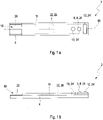
- FIG. 1 a schematic top view of a sensor 2 not according to the invention is shown.
- the sensor 2 comprises a substrate 4 made from a Melinex ® foil from DuPont Teijin Films, Europe.
- the sensor 2 has a rectangular shape; however the sensor 2 can have any form that is suitable to detect an analyte in a sample 26.
- the sensor 2 has a length of 2 cm, a width of 0.5 mm and a height of 0.15 mm in the contacting region 16.
- the height of the rest of the sensor 2 might be greater than 0.15 mm as the electrodes 6, 10, 12 and/or the isolation layer 18 may be thicker in this region of the sensor 2.
- the height of the sensor in the region outside of the contacting region may be in the range from 0.15 to 2 mm.
- each conductive contact lead 28 On a sensor surface 20 of the substrate 4, three conductive contact leads 28 are positioned next to each other with a distance of 0.05 mm each. The width of each conductive contact lead 28 is 0.05 mm. The conductive contact leads 28 build three parallel lines made of gold. At one end of the substrate 4, in figure 1 on the left hand side, a contacting region 16 is positioned. The starting points of the conductive contact leads 28 build a line perpendicular to the left boarder of the substrate 4. The length of each conductive contact lead 28 can vary depending on the electrode they are contacted with. In this example the conductive contact lead 28 in the middle of the sensor 2 is the shortest as it is contacted to the reference electrode 10. The conductive contact leads 28 have a length in a range of 1.5 to 1.9 cm. The longest conductive lead 28 is that contacted to the counter electrode 12. The conductive contact lead 28 contacted with the working electrode 6 provides a curve at the right end of the substrate 4 to reach that the first electrode material 24 can be positioned on the center axis 80 of
- the substrate 4 can expand its width in the contacting region 16 of the sensor 2.
- the contacting region 16 can have a dimension of 0.5 cm in length, 4.5 mm in width and 0.15 mm in height.
- the width of the sensor 2 is broadened in this part of the sensor 2.
- the broadened contacting region 16 of the substrate 4 can be positioned asymmetrically, only on one side of the sensor 2 or symmetrically on both sides of the sensor 2.
- the conductive contact leads 28 might be broader than on the rest of the substrate 4. In the contacting region 16 the conductive contact leads 28 have a width of 1 mm over a length of 0.5 cm. The height stays the same as mentioned above. In the contacting region 16 of the sensor 2 the conductive contact leads 28 end. This is the region where a detection device 52 can be connected with the sensor 2 as shown in figure 5 . On the three conductive leads 28, three different electrode materials 24, 24' are positioned.
- the working electrode 6 comprises a first electrode material 24, in the form of a graphite matrix with glucose oxidase and Mn 2 O 3 .
- the reference electrode 10 comprises a further electrode material 24', in form of an Ag/AgCl and the counter electrode 12 comprises a further electrode material as described in the examples.
- An isolation layer 18 covers the working electrode 6, the reference electrode 10 and the counter electrode 12.
- the isolation layer 18 can also cover most of the substrate 4 and the conductive contact leads 28.
- the height of the isolation layer 18 is in the range of from 0.01 to 0.02 mm.
- one end of each of the conductive contact leads 28 is not covered by the isolation layer 18.
- the isolation layer provides at least one hole for contacting the contact leads 28. This is the part of the sensor 2 that can be contacted by the detection device 52.
- the position of the electrodes 6, 10, 12 can vary. It is not obligatory that the working electrode 6 is positioned in the middle of the three electrodes 6, 10, 12. It is also possible to position the reference electrode 10 or the counter electrode 12 in the middle of the substrate 4. If the sensor 2 was dip coated to cover it with a protective layer, the surface opposite to the illustrated sensor surface 20 is also covered by the protective layer (not shown here).
- the sensor 2 is shown as a side view. Compared to the top view of figure 1a the sensor 2 shown in figure 1a is rotated about the dotted line 80 in the middle of the sensor 2 for 90 °. In this side view the sequence of the materials of the sensor 2 is illustrated.
- the sensor 2 of figure 1b shows a layered structure. At the bottom of the sensor 2 the substrate 4 builds the first layer as base of the sensor 2.
- a layer of a conductive contact lead 28 is positioned on the substrate 2 .
- an isolation layer 18 is positioned, beside the contact region 16 and the part of the conductive material 22 where the first electrode material 24 is positioned to build the working electrode 6, a further electrode material 24' to build the reference electrode 10 and a further electrode material to build the counter electrode 12.
- the conductive contact lead 28 is connected to the further electrode material 24' of the reference electrode 10.
- a further protective layer such as a diffusion membrane, on the whole sensor 2 beside the contacting region 16.
- a protective layer may cover the sensor 2 beside the contacting region 16.
- the protective layer can be a biocompatible material when the sensor should be at least partly introduced into a human body.
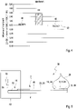
- Figure 2 shows a diagram of measurement values 34, 36 of two sensors at different polarization voltages at a constant concentration of H 2 O 2 as analyte.
- One of the sensors comprised a working electrode 6 of PE401 (Acheson, see examples) and is symbolized by the squares 36.
- the other sensor comprised a working electrode 6 with Mn 2 O 3 comprised 84,6 wt.-% (Acheson PE401), 15,4 wt.-% Mn 2 O 3 , symbolized by the rhombs 34.
- the counter electrodes 12 of both sensors comprised 100 wt.-% of Acheson PE401.
- the reference electrode 10 of both sensors comprised Electrodag 6037SS (Acheson).
- the two sensors with and without Mn 2 O 3 resulting in measurement values 34 and 36 both comprised a similar composition of the counter electrodes 12.
- the two sensors were independently positioned in a 10 mM phosphate buffer pH 7.4 with 147 mM NaCl and 50 ⁇ M H 2 O 2 in a way that the electrodes 6, 10, 12 are dipped into the buffer solution.
- the buffer solution was prepared by solving the mentioned salts in deionized water by Milli-Q Academic (Merck Millipore) for 30 minutes at a temperature of 37 °C before adding the H 2 O 2 .
- the sensors were dipped into the so prepared buffer solution.
- the sensors were contacted by the contacting region to a Gamry potentiostat G300 from Gamry Instruments (USA).
- the power supply was regulated to supply 325 mV (vs Ag/AgCl 3M KCl) between the working and the reference electrode at the start of the measurement. This voltage was fixed for 10 minutes. After that period the voltage was changed for eight times to a further voltage 50 mV less than the foregoing voltage ending at -75 mV. After each change of the voltage a measurement of the current was established for 10 minutes. The current was measured by the detection device. Results for the sensor comprising Mn 2 O 3 and for the sensor without Mn 2 O 3 are shown in Figure 2 .
- the sensor with Mn 2 O 3 represented by measurement values 34 shows a change of current starting from 325 mV to about 175 mV. From 175 mV to 25 mV the sensor with Mn 2 O 3 delivers a constant current in a range of -25 to 40 nA.
- the sensor with Mn 2 O 3 delivers stable current results.
- the increase of the current beyond the 25 mV to negative voltages result in a reaction of the electrode with oxygen O 2 included in the solution.
- Figure 3 shows a diagram of a measurement of a sensor 2 with a working electrode 6 comprising graphite, GOD and Mn 2 O 3 , a reference electrode 10 and a counter electrode 12, all prepared as described in the example section above.
- the sensor 2 was dipped into a buffer solution as prepared for the experiments of Figure 2 without the addition of H 2 O 2 .
- the setup of the measuring system was the same as for the experiments of Figure 2 .
- At a voltage of 125 mV between the working electrode 6 and the reference electrode 10 the current was measured by the detection device. After 25 minute equilibration a current of 0.8 nA was measured. After this measurement the sensor 2 was dipped into a buffer solution as described before with 5 mM Glucose.
- FIG 4 the influence on the measurement results of a sensor as described for Figure 3 by adding different interference materials are shown.
- the first block 40 represents the percentage of interference with the signal when 2 mg/dl ascorbic acid was added to a buffer solution as described for the measurements in Figure 2 and 3 , containing glucose with a concentration of 10 mM. After 25 minute equilibration the current was measured.
- the same buffer was used for the interference measurements of second block 44 representing the disturbance of uric acid with a concentration of 8 mg/dl.
- a third interfering material was acetaminophen in a concentration of 3 mg/dl represented by the third block 46 of the block diagram.
- the interference of uric acid is the greatest.
- an increase of the signal is provoked by adding uric acid to the sample solution.
- the acetaminophen has a decreasing effect on the signal of the sensor.
- the disturbance of ascorbic acid and acetaminophen is in the range of the normal error of measurement.
- the measured error of the sensor has been diminished compared to state of the art sensors.
- FIG 5 a sensor system 50 not according to the present invention is shown.
- a sensor 2 with the same geometry and components as described in Figure 1a and 1b , is positioned with its contacting region 16 into a detector device 52.
- the detector device 52 provides at least one contact 54 for contacting the conductive contact leads 28 that lead to the working electrode 6, the reference electrode 10 and the counter electrode 12.
- each conductive contact lead 28 is contacted by one contact 54 of the detector device 52.
- the detector device 52 is able to deliver and keep a constant voltage between the working electrode 6 and the reference electrode 10.
- the measured current between the working electrode 6 and the counter electrode 12 delivers the measurement signal that is proportional to the analyte concentration, when applying the formulas I and II.
- This current is measured by an electrical detector 56 that measures the current between the electrodes 6 and 12, which is part of the detector device 52.
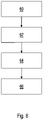
- a scheme of the process for manufacturing a sensor not according to the invention is shown.
- the substrate 4 is provided, wherein the substrate 4 comprises a sensor surface 20.
- Providing the substrate in the first step P1 60 is achieved by unrolling a foil of polyimide which is stored on a roll.
- the foil has a thickness of 0.5 mm.
- One end of the foil is wound around a second roll.
- the distance of the rolls is in a range of from 1 to 100 m. In one example the distance is about 10m.
- the foil has a width of 1 m.
- the shape of the sensor is embossed about 100 fold per meter in the foil.
- a conductive material 22 in form of gold is applied to the sensor surface 22 in the second step P2 62 by a sputtering process.
- the conductive contact leads 28 are formed out of the gold layer by scratching off the superfluous parts of gold.
- the first electrode material 24 is applied to the conductive contact leads 28 in the third step P3 64 to form a working electrode 6 or a working electrode pad 8.
- the first electrode material 24 is applied to the conductive contact leads 28 in a way as described in example 1 above.
- the reference electrode 10 and/or counter electrode 12 are applied to the conductive contact leads 28 as described in examples 2 or 3 above.
- a fifth step P5 can be applied (not shown) to cover at least a part of the sensor 2 with a biocompatible membrane and/or a protective layer. This is achieved according example 4 as described above.
Landscapes
- Health & Medical Sciences (AREA)
- Life Sciences & Earth Sciences (AREA)
- Chemical & Material Sciences (AREA)
- Engineering & Computer Science (AREA)
- Immunology (AREA)
- Physics & Mathematics (AREA)
- Molecular Biology (AREA)
- Organic Chemistry (AREA)
- General Health & Medical Sciences (AREA)
- Analytical Chemistry (AREA)
- Biochemistry (AREA)
- Proteomics, Peptides & Aminoacids (AREA)
- Biophysics (AREA)
- Wood Science & Technology (AREA)
- Zoology (AREA)
- Pathology (AREA)
- Hematology (AREA)
- Biotechnology (AREA)
- Microbiology (AREA)
- Biomedical Technology (AREA)
- Chemical Kinetics & Catalysis (AREA)
- General Physics & Mathematics (AREA)
- Urology & Nephrology (AREA)
- General Engineering & Computer Science (AREA)
- Bioinformatics & Cheminformatics (AREA)
- Genetics & Genomics (AREA)
- Electrochemistry (AREA)
- Heart & Thoracic Surgery (AREA)
- Animal Behavior & Ethology (AREA)
- Food Science & Technology (AREA)
- Medicinal Chemistry (AREA)
- General Chemical & Material Sciences (AREA)
- Optics & Photonics (AREA)
- Emergency Medicine (AREA)
- Medical Informatics (AREA)
- Surgery (AREA)
- Cell Biology (AREA)
- Public Health (AREA)
- Veterinary Medicine (AREA)
- Measurement Of The Respiration, Hearing Ability, Form, And Blood Characteristics Of Living Organisms (AREA)
Claims (1)
- Procédé pour détecter un analyte qui est susceptible de générer du H2O2 dans un échantillon, le procédé comprenant les étapes suivantes :S1. la fourniture d'un capteur (2), le capteur (2) comprenant :a. un matériau conducteur (22) ;b. un premier matériau d'électrode (24) chevauchant au moins une partie du matériau conducteur (22) pour former une électrode de travail (6),dans lequel le premier matériau d'électrode (24) est conçu pour effectuer au moins une réaction de détection lorsque l'analyte est présent dans l'échantillon,
et dans lequel du H2O2 est généré dans la réaction de détection, dans lequel le premier matériau d'électrode comprend des particules de Mn2O3 ; et dans lequel le premier matériau d'électrode comprend en outre une enzyme, dans lequel l'enzyme est une oxydase ;S2. l'application d'une tension à l'électrode de travail (6) ;dans lequel la tension est choisie dans la plage de tension à laquelle le H2O2 dans l'échantillon sera réduit au niveau de l'électrode de travail (6), générant de ce fait un courant électrique,dans lequel la tension est dans une plage de 50 à 150 mV si on compare à une électrode de référence comprenant Ag/AgCl avec 3 M KCl,le procédé comprenant en outre la détection du courant électrique,
dans lequel le courant électrique correspond à une mesure d'une concentration de l'analyte dans l'échantillon.
Priority Applications (7)
| Application Number | Priority Date | Filing Date | Title |
|---|---|---|---|
| ES13157968T ES2922701T3 (es) | 2013-03-06 | 2013-03-06 | Procedimiento para detectar un analito usando un sensor con catalizador de Mn2O3 |
| EP13157968.2A EP2774538B1 (fr) | 2013-03-06 | 2013-03-06 | Procédé de détection d'un analyte à l'aide d'un capteur avec catalyseur Mn2O3 |
| HUE13157968A HUE059358T2 (hu) | 2013-03-06 | 2013-03-06 | Eljárás egy analit érzékelésére Mn2O3 katalizátorral rendelkezõ szenzor használatával |
| CA2839793A CA2839793A1 (fr) | 2013-03-06 | 2014-01-17 | Capteur equipe d'un catalyseur mn2o3 et procede de fabrication dudit capteur |
| RU2014106908/28A RU2577560C2 (ru) | 2013-03-06 | 2014-02-25 | Датчик, содержащий оксид марганца (iii) в качестве катализатора, и способ изготовления датчика |
| US14/199,003 US10330627B2 (en) | 2013-03-06 | 2014-03-06 | Biosensors and biosensor systems with Mn2O3 catalyst as well as methods of making and using the same |
| CN201410080313.2A CN104049014B (zh) | 2013-03-06 | 2014-03-06 | 具有Mn2O3催化剂的传感器及其制造方法 |
Applications Claiming Priority (1)
| Application Number | Priority Date | Filing Date | Title |
|---|---|---|---|
| EP13157968.2A EP2774538B1 (fr) | 2013-03-06 | 2013-03-06 | Procédé de détection d'un analyte à l'aide d'un capteur avec catalyseur Mn2O3 |
Publications (2)
| Publication Number | Publication Date |
|---|---|
| EP2774538A1 EP2774538A1 (fr) | 2014-09-10 |
| EP2774538B1 true EP2774538B1 (fr) | 2022-05-25 |
Family
ID=47900644
Family Applications (1)
| Application Number | Title | Priority Date | Filing Date |
|---|---|---|---|
| EP13157968.2A Active EP2774538B1 (fr) | 2013-03-06 | 2013-03-06 | Procédé de détection d'un analyte à l'aide d'un capteur avec catalyseur Mn2O3 |
Country Status (7)
| Country | Link |
|---|---|
| US (1) | US10330627B2 (fr) |
| EP (1) | EP2774538B1 (fr) |
| CN (1) | CN104049014B (fr) |
| CA (1) | CA2839793A1 (fr) |
| ES (1) | ES2922701T3 (fr) |
| HU (1) | HUE059358T2 (fr) |
| RU (1) | RU2577560C2 (fr) |
Families Citing this family (18)
| Publication number | Priority date | Publication date | Assignee | Title |
|---|---|---|---|---|
| US20150122645A1 (en) * | 2013-11-07 | 2015-05-07 | Medtronic Minimed, Inc. | Enzyme matrices for biosensors |
| CN104655700B (zh) * | 2015-03-17 | 2017-09-22 | 信阳师范学院 | 食品防腐剂电化学传感器及其制备方法与应用 |
| CN104865304A (zh) * | 2015-04-09 | 2015-08-26 | 宁波大学 | 一种基于Mn2O3参比电极的YSZ基HCs气敏传感器 |
| GB201604248D0 (en) * | 2016-03-11 | 2016-04-27 | Augmented Optics Ltd | Electrically conducting hydrophilic co-polymers |
| TWI589870B (zh) * | 2016-05-05 | 2017-07-01 | Vida Biotechnology Co Ltd | Biological test strip with isolated structure and method of use |
| WO2018075824A1 (fr) * | 2016-10-20 | 2018-04-26 | EnLiSense, LLC | Ensemble de détection à configurations multiples et procédés d'utilisation correspondants |
| ES3023573T3 (en) * | 2017-09-18 | 2025-06-02 | Hoffmann La Roche | Electrochemical sensor for detecting at least one analyte |
| RU2698014C2 (ru) * | 2017-12-28 | 2019-08-21 | Федеральное государственное автономное образовательное учреждение высшего образования "Балтийский федеральный университет имени Иммануила Канта" | Датчик температуры для устройства оптогенетического контроля функций мозга |
| US11744492B2 (en) * | 2018-08-29 | 2023-09-05 | Medtronic, Inc. | Electrochemical sensor including multiple work electrodes and common reference electrode |
| CN110244546A (zh) * | 2019-05-29 | 2019-09-17 | 华为技术有限公司 | 用于智能手表的一体结构和智能手表 |
| RU197895U1 (ru) * | 2020-02-05 | 2020-06-04 | Общество с ограниченной ответственностью "МедТехПродукт" | Электрохимический биосенсор для определения концентрации глюкозы в крови |
| MY208843A (en) * | 2020-03-26 | 2025-06-02 | Univ Malaya | An electrochemical sensor for detecting and characterizing a biological material |
| EP4000514A1 (fr) * | 2020-11-12 | 2022-05-25 | Roche Diabetes Care GmbH | Procédé de production d'un capteur d'analyte, capteur d'analyte et son utilisation |
| TWI839631B (zh) * | 2021-08-24 | 2024-04-21 | 國立臺灣大學 | 用以監測過氧化氫之一次性感測元件及其製造方法 |
| US12287305B2 (en) * | 2021-10-06 | 2025-04-29 | The Regents Of The University Of California | Microfluidic sensing devices |
| RU209089U1 (ru) * | 2021-10-22 | 2022-02-01 | Кирилл Владимирович Романенко | Электрохимический биосенсор для определения концентрации глюкозы в крови |
| DE102022204434A1 (de) | 2021-11-26 | 2023-06-01 | Heraeus Deutschland GmbH & Co. KG | Edelmetallbeschichtungen mit kontrollierter morphologie |
| EP4493059A1 (fr) * | 2022-03-18 | 2025-01-22 | DexCom, Inc. | Systèmes de capteurs multi-analytes continus |
Family Cites Families (20)
| Publication number | Priority date | Publication date | Assignee | Title |
|---|---|---|---|---|
| JPS56119837A (en) * | 1980-02-27 | 1981-09-19 | Yazaki Corp | Gas sensor of semiconductor |
| US4679562A (en) * | 1983-02-16 | 1987-07-14 | Cardiac Pacemakers, Inc. | Glucose sensor |
| US5225064A (en) * | 1992-01-15 | 1993-07-06 | Enzyme Technology Research Group, Inc. | Peroxidase colloidal gold oxidase biosensors for mediatorless glucose determination |
| AT397513B (de) | 1992-12-15 | 1994-04-25 | Avl Verbrennungskraft Messtech | Amperometrische enzymelektrode |
| US6706473B1 (en) * | 1996-12-06 | 2004-03-16 | Nanogen, Inc. | Systems and devices for photoelectrophoretic transport and hybridization of oligonucleotides |
| US7813780B2 (en) * | 2005-12-13 | 2010-10-12 | Medtronic Minimed, Inc. | Biosensors and methods for making and using them |
| ES2341963T3 (es) * | 2003-09-30 | 2010-06-30 | F. Hoffmann-La Roche Ag | Detector con biocompatibilidad mejorada. |
| JP4238715B2 (ja) * | 2003-12-15 | 2009-03-18 | 富士ゼロックス株式会社 | 電気化学測定用電極 |
| WO2005099057A1 (fr) * | 2004-03-31 | 2005-10-20 | Nec Corporation | Plaque pour élément émetteur de lumière de semi-conducteur de nitrures, méthode de fabrication de celle-ci et élément émetteur de lumière de semi-conducteur de nitrures obtenu à partir de la plaque |
| US7713392B2 (en) * | 2005-04-15 | 2010-05-11 | Agamatrix, Inc. | Test strip coding and quality measurement |
| US20060270053A1 (en) * | 2005-05-26 | 2006-11-30 | General Electric Company | Apparatus, methods, and systems having gas sensor with catalytic gate and variable bias |
| RU2291417C1 (ru) * | 2005-09-05 | 2007-01-10 | Государственное образовательное учреждение высшего профессионального образования "Московский энергетический институт (технический университет") (ГОУВПО "МЭИ (ТУ)") | Датчик определения концентрации газов |
| ATE433711T1 (de) | 2005-12-19 | 2009-07-15 | Hoffmann La Roche | Sandwichsensor zur ermittlung einer analytkonzentration |
| EP2017350A1 (fr) * | 2007-07-19 | 2009-01-21 | F. Hoffmann-La Roche AG | Capteur électrochimique doté d'une enzyme liée de manière covalente |
| CN101530328B (zh) * | 2009-04-20 | 2013-06-19 | 湖州美奇医疗器械有限公司 | 皮下植入式的葡萄糖传感器及其制作方法 |
| ES2390404T3 (es) * | 2009-05-15 | 2012-11-12 | F.Hoffmann-La Roche Ag | Estabilización de enzima en sensores electroquímicos |
| EP2544582B1 (fr) * | 2010-03-11 | 2017-02-22 | Roche Diabetes Care GmbH | Procédé pour la mesure électrochimique d'une concentration en analyte in vivo et pile à combustible à cet effet |
| US8617372B2 (en) * | 2011-03-11 | 2013-12-31 | Ut-Battelle, Llc | Array-type NH3 sensor |
| SI2697388T1 (sl) * | 2011-03-28 | 2015-07-31 | F. Hoffmann-La Roche Ag | Izboljšan difuzijski sloj za encimski in-vivo senzor |
| CN102920465A (zh) * | 2012-10-26 | 2013-02-13 | 浙江大学 | 葡萄糖传感器 |
-
2013
- 2013-03-06 EP EP13157968.2A patent/EP2774538B1/fr active Active
- 2013-03-06 ES ES13157968T patent/ES2922701T3/es active Active
- 2013-03-06 HU HUE13157968A patent/HUE059358T2/hu unknown
-
2014
- 2014-01-17 CA CA2839793A patent/CA2839793A1/fr not_active Abandoned
- 2014-02-25 RU RU2014106908/28A patent/RU2577560C2/ru not_active IP Right Cessation
- 2014-03-06 US US14/199,003 patent/US10330627B2/en active Active
- 2014-03-06 CN CN201410080313.2A patent/CN104049014B/zh active Active
Non-Patent Citations (1)
| Title |
|---|
| DODEVSKA T ET AL: "Electrocatalytic reduction of hydrogen peroxide on modified graphite electrodes: application to the development of glucose biosensors", ANALYTICAL AND BIOANALYTICAL CHEMISTRY, SPRINGER, BERLIN, DE, vol. 386, no. 5, 12 September 2006 (2006-09-12), pages 1413 - 1418, XP019441133, ISSN: 1618-2650, DOI: 10.1007/S00216-006-0682-0 * |
Also Published As
| Publication number | Publication date |
|---|---|
| US10330627B2 (en) | 2019-06-25 |
| EP2774538A1 (fr) | 2014-09-10 |
| HUE059358T2 (hu) | 2022-11-28 |
| CA2839793A1 (fr) | 2014-09-06 |
| CN104049014B (zh) | 2018-04-27 |
| RU2014106908A (ru) | 2015-08-27 |
| RU2577560C2 (ru) | 2016-03-20 |
| CN104049014A (zh) | 2014-09-17 |
| ES2922701T3 (es) | 2022-09-19 |
| US20140251826A1 (en) | 2014-09-11 |
Similar Documents
| Publication | Publication Date | Title |
|---|---|---|
| EP2774538A1 (fr) | Capteur avec catalyseur Mn2O3 et son procédé de fabrication | |
| EP3032250B1 (fr) | Procédé de mesure de substance et dispositif de mesure employant un biocapteur électrochimique | |
| EP2866024A1 (fr) | Électrode enzymatique | |
| CN107202826B (zh) | 使用电化学式生物传感器的物质测定方法和测定装置 | |
| AU2005295106A1 (en) | Concentration determination in a diffusion barrier layer | |
| WO2005088288A1 (fr) | Biocapteur à nanotube de carbone | |
| CN114269246A (zh) | 用于测量生物信号的包含碳纳米管的电化学生物传感器及其制造方法 | |
| EP3928697A1 (fr) | Capteur d'analyte et procédé de production d'un capteur d'analyte | |
| EP3457121A1 (fr) | Capteur électrochimique et système de capteur pour détecter au moins un analyte | |
| CN102781308B (zh) | 用于体内分析物浓度的电化学测量的方法以及用于该方法的燃料电池 | |
| EP1859048A2 (fr) | Stabilisation d'activite enzymatique de biocapteurs electrochimiques | |
| EP2840144A1 (fr) | Procédé de fabrication d'un élément de détection à sec pour une détermination enzymatique d'un analyte dans un fluide corporel et élément de détection à sec | |
| ES3028841T3 (en) | Galvanically functionalized sensors | |
| US12566149B2 (en) | Electrochemical system and implantable biochemical test chip | |
| EP2696201A1 (fr) | Capteurs de détection électrochimique sélective d'espèces oxygénées et azotées réactives dans des milieux fluides | |
| US12390134B2 (en) | Method of manufacturing a sensor for detecting an analyte in a body fluid | |
| HK1197691B (en) | Sensor with mn203 catalyst and process for manufacturing the same | |
| HK1197691A (en) | Sensor with mn203 catalyst and process for manufacturing the same | |
| HK40093318A (en) | Analyte sensor and a method for producing an analyte sensor | |
| EP2840143A1 (fr) | Procédé de fabrication d'un élément de détection à sec pour une détermination enzymatique d'un analyte dans un fluide corporel et élément de détection à sec | |
| HK40095780A (en) | Electrochemical sensor and sensor system for detecting at least one analyte | |
| KR20230104120A (ko) | 분석물 센서의 적어도 하나의 전극을 제조하기 위한 방법 | |
| HK40003925A (zh) | 电功能化的传感器 | |
| HK1116220A (en) | Stabilizing the activity of pqq-dependent glucose dehydrogenase in electrochemical biosensors |
Legal Events
| Date | Code | Title | Description |
|---|---|---|---|
| PUAI | Public reference made under article 153(3) epc to a published international application that has entered the european phase |
Free format text: ORIGINAL CODE: 0009012 |
|
| 17P | Request for examination filed |
Effective date: 20130306 |
|
| AK | Designated contracting states |
Kind code of ref document: A1 Designated state(s): AL AT BE BG CH CY CZ DE DK EE ES FI FR GB GR HR HU IE IS IT LI LT LU LV MC MK MT NL NO PL PT RO RS SE SI SK SM TR |
|
| AX | Request for extension of the european patent |
Extension state: BA ME |
|
| R17P | Request for examination filed (corrected) |
Effective date: 20150202 |
|
| RBV | Designated contracting states (corrected) |
Designated state(s): AL AT BE BG CH CY CZ DE DK EE ES FI FR GB GR HR HU IE IS IT LI LT LU LV MC MK MT NL NO PL PT RO RS SE SI SK SM TR |
|
| RAP1 | Party data changed (applicant data changed or rights of an application transferred) |
Owner name: ROCHE DIABETES CARE GMBH Owner name: F. HOFFMANN-LA ROCHE AG |
|
| STAA | Information on the status of an ep patent application or granted ep patent |
Free format text: STATUS: EXAMINATION IS IN PROGRESS |
|
| 17Q | First examination report despatched |
Effective date: 20180626 |
|
| REG | Reference to a national code |
Ref country code: DE Ref legal event code: R079 Ref document number: 602013081724 Country of ref document: DE Free format text: PREVIOUS MAIN CLASS: A61B0005145000 Ipc: A61B0005148600 |
|
| GRAP | Despatch of communication of intention to grant a patent |
Free format text: ORIGINAL CODE: EPIDOSNIGR1 |
|
| STAA | Information on the status of an ep patent application or granted ep patent |
Free format text: STATUS: GRANT OF PATENT IS INTENDED |
|
| RIC1 | Information provided on ipc code assigned before grant |
Ipc: C12Q 1/00 20060101ALI20211216BHEP Ipc: G01N 27/327 20060101ALI20211216BHEP Ipc: G01N 33/543 20060101ALI20211216BHEP Ipc: A61B 5/1486 20060101AFI20211216BHEP |
|
| INTG | Intention to grant announced |
Effective date: 20220118 |
|
| GRAS | Grant fee paid |
Free format text: ORIGINAL CODE: EPIDOSNIGR3 |
|
| GRAA | (expected) grant |
Free format text: ORIGINAL CODE: 0009210 |
|
| STAA | Information on the status of an ep patent application or granted ep patent |
Free format text: STATUS: THE PATENT HAS BEEN GRANTED |
|
| AK | Designated contracting states |
Kind code of ref document: B1 Designated state(s): AL AT BE BG CH CY CZ DE DK EE ES FI FR GB GR HR HU IE IS IT LI LT LU LV MC MK MT NL NO PL PT RO RS SE SI SK SM TR |
|
| REG | Reference to a national code |
Ref country code: GB Ref legal event code: FG4D |
|
| REG | Reference to a national code |
Ref country code: CH Ref legal event code: EP |
|
| REG | Reference to a national code |
Ref country code: DE Ref legal event code: R096 Ref document number: 602013081724 Country of ref document: DE |
|
| REG | Reference to a national code |
Ref country code: AT Ref legal event code: REF Ref document number: 1493932 Country of ref document: AT Kind code of ref document: T Effective date: 20220615 |
|
| REG | Reference to a national code |
Ref country code: IE Ref legal event code: FG4D |
|
| REG | Reference to a national code |
Ref country code: FI Ref legal event code: FGE |
|
| REG | Reference to a national code |
Ref country code: LT Ref legal event code: MG9D |
|
| REG | Reference to a national code |
Ref country code: ES Ref legal event code: FG2A Ref document number: 2922701 Country of ref document: ES Kind code of ref document: T3 Effective date: 20220919 |
|
| REG | Reference to a national code |
Ref country code: NL Ref legal event code: MP Effective date: 20220525 |
|
| REG | Reference to a national code |
Ref country code: AT Ref legal event code: MK05 Ref document number: 1493932 Country of ref document: AT Kind code of ref document: T Effective date: 20220525 |
|
| PG25 | Lapsed in a contracting state [announced via postgrant information from national office to epo] |
Ref country code: SE Free format text: LAPSE BECAUSE OF FAILURE TO SUBMIT A TRANSLATION OF THE DESCRIPTION OR TO PAY THE FEE WITHIN THE PRESCRIBED TIME-LIMIT Effective date: 20220525 Ref country code: PT Free format text: LAPSE BECAUSE OF FAILURE TO SUBMIT A TRANSLATION OF THE DESCRIPTION OR TO PAY THE FEE WITHIN THE PRESCRIBED TIME-LIMIT Effective date: 20220926 Ref country code: NO Free format text: LAPSE BECAUSE OF FAILURE TO SUBMIT A TRANSLATION OF THE DESCRIPTION OR TO PAY THE FEE WITHIN THE PRESCRIBED TIME-LIMIT Effective date: 20220825 Ref country code: NL Free format text: LAPSE BECAUSE OF FAILURE TO SUBMIT A TRANSLATION OF THE DESCRIPTION OR TO PAY THE FEE WITHIN THE PRESCRIBED TIME-LIMIT Effective date: 20220525 Ref country code: LT Free format text: LAPSE BECAUSE OF FAILURE TO SUBMIT A TRANSLATION OF THE DESCRIPTION OR TO PAY THE FEE WITHIN THE PRESCRIBED TIME-LIMIT Effective date: 20220525 Ref country code: HR Free format text: LAPSE BECAUSE OF FAILURE TO SUBMIT A TRANSLATION OF THE DESCRIPTION OR TO PAY THE FEE WITHIN THE PRESCRIBED TIME-LIMIT Effective date: 20220525 Ref country code: GR Free format text: LAPSE BECAUSE OF FAILURE TO SUBMIT A TRANSLATION OF THE DESCRIPTION OR TO PAY THE FEE WITHIN THE PRESCRIBED TIME-LIMIT Effective date: 20220826 Ref country code: BG Free format text: LAPSE BECAUSE OF FAILURE TO SUBMIT A TRANSLATION OF THE DESCRIPTION OR TO PAY THE FEE WITHIN THE PRESCRIBED TIME-LIMIT Effective date: 20220825 Ref country code: AT Free format text: LAPSE BECAUSE OF FAILURE TO SUBMIT A TRANSLATION OF THE DESCRIPTION OR TO PAY THE FEE WITHIN THE PRESCRIBED TIME-LIMIT Effective date: 20220525 |
|
| REG | Reference to a national code |
Ref country code: HU Ref legal event code: AG4A Ref document number: E059358 Country of ref document: HU |
|
| PG25 | Lapsed in a contracting state [announced via postgrant information from national office to epo] |
Ref country code: RS Free format text: LAPSE BECAUSE OF FAILURE TO SUBMIT A TRANSLATION OF THE DESCRIPTION OR TO PAY THE FEE WITHIN THE PRESCRIBED TIME-LIMIT Effective date: 20220525 Ref country code: PL Free format text: LAPSE BECAUSE OF FAILURE TO SUBMIT A TRANSLATION OF THE DESCRIPTION OR TO PAY THE FEE WITHIN THE PRESCRIBED TIME-LIMIT Effective date: 20220525 Ref country code: LV Free format text: LAPSE BECAUSE OF FAILURE TO SUBMIT A TRANSLATION OF THE DESCRIPTION OR TO PAY THE FEE WITHIN THE PRESCRIBED TIME-LIMIT Effective date: 20220525 Ref country code: IS Free format text: LAPSE BECAUSE OF FAILURE TO SUBMIT A TRANSLATION OF THE DESCRIPTION OR TO PAY THE FEE WITHIN THE PRESCRIBED TIME-LIMIT Effective date: 20220925 |
|
| PG25 | Lapsed in a contracting state [announced via postgrant information from national office to epo] |
Ref country code: SM Free format text: LAPSE BECAUSE OF FAILURE TO SUBMIT A TRANSLATION OF THE DESCRIPTION OR TO PAY THE FEE WITHIN THE PRESCRIBED TIME-LIMIT Effective date: 20220525 Ref country code: SK Free format text: LAPSE BECAUSE OF FAILURE TO SUBMIT A TRANSLATION OF THE DESCRIPTION OR TO PAY THE FEE WITHIN THE PRESCRIBED TIME-LIMIT Effective date: 20220525 Ref country code: EE Free format text: LAPSE BECAUSE OF FAILURE TO SUBMIT A TRANSLATION OF THE DESCRIPTION OR TO PAY THE FEE WITHIN THE PRESCRIBED TIME-LIMIT Effective date: 20220525 Ref country code: DK Free format text: LAPSE BECAUSE OF FAILURE TO SUBMIT A TRANSLATION OF THE DESCRIPTION OR TO PAY THE FEE WITHIN THE PRESCRIBED TIME-LIMIT Effective date: 20220525 Ref country code: CZ Free format text: LAPSE BECAUSE OF FAILURE TO SUBMIT A TRANSLATION OF THE DESCRIPTION OR TO PAY THE FEE WITHIN THE PRESCRIBED TIME-LIMIT Effective date: 20220525 |
|
| REG | Reference to a national code |
Ref country code: DE Ref legal event code: R097 Ref document number: 602013081724 Country of ref document: DE |
|
| PG25 | Lapsed in a contracting state [announced via postgrant information from national office to epo] |
Ref country code: AL Free format text: LAPSE BECAUSE OF FAILURE TO SUBMIT A TRANSLATION OF THE DESCRIPTION OR TO PAY THE FEE WITHIN THE PRESCRIBED TIME-LIMIT Effective date: 20220525 |
|
| PLBE | No opposition filed within time limit |
Free format text: ORIGINAL CODE: 0009261 |
|
| STAA | Information on the status of an ep patent application or granted ep patent |
Free format text: STATUS: NO OPPOSITION FILED WITHIN TIME LIMIT |
|
| 26N | No opposition filed |
Effective date: 20230228 |
|
| PG25 | Lapsed in a contracting state [announced via postgrant information from national office to epo] |
Ref country code: SI Free format text: LAPSE BECAUSE OF FAILURE TO SUBMIT A TRANSLATION OF THE DESCRIPTION OR TO PAY THE FEE WITHIN THE PRESCRIBED TIME-LIMIT Effective date: 20220525 |
|
| PG25 | Lapsed in a contracting state [announced via postgrant information from national office to epo] |
Ref country code: MC Free format text: LAPSE BECAUSE OF FAILURE TO SUBMIT A TRANSLATION OF THE DESCRIPTION OR TO PAY THE FEE WITHIN THE PRESCRIBED TIME-LIMIT Effective date: 20220525 |
|
| REG | Reference to a national code |
Ref country code: CH Ref legal event code: PL |
|
| REG | Reference to a national code |
Ref country code: BE Ref legal event code: MM Effective date: 20230331 |
|
| PG25 | Lapsed in a contracting state [announced via postgrant information from national office to epo] |
Ref country code: LU Free format text: LAPSE BECAUSE OF NON-PAYMENT OF DUE FEES Effective date: 20230306 |
|
| PG25 | Lapsed in a contracting state [announced via postgrant information from national office to epo] |
Ref country code: LI Free format text: LAPSE BECAUSE OF NON-PAYMENT OF DUE FEES Effective date: 20230331 Ref country code: CH Free format text: LAPSE BECAUSE OF NON-PAYMENT OF DUE FEES Effective date: 20230331 |
|
| PG25 | Lapsed in a contracting state [announced via postgrant information from national office to epo] |
Ref country code: BE Free format text: LAPSE BECAUSE OF NON-PAYMENT OF DUE FEES Effective date: 20230331 |
|
| PG25 | Lapsed in a contracting state [announced via postgrant information from national office to epo] |
Ref country code: BG Free format text: LAPSE BECAUSE OF FAILURE TO SUBMIT A TRANSLATION OF THE DESCRIPTION OR TO PAY THE FEE WITHIN THE PRESCRIBED TIME-LIMIT Effective date: 20220525 |
|
| PG25 | Lapsed in a contracting state [announced via postgrant information from national office to epo] |
Ref country code: BG Free format text: LAPSE BECAUSE OF FAILURE TO SUBMIT A TRANSLATION OF THE DESCRIPTION OR TO PAY THE FEE WITHIN THE PRESCRIBED TIME-LIMIT Effective date: 20220525 |
|
| PG25 | Lapsed in a contracting state [announced via postgrant information from national office to epo] |
Ref country code: CY Free format text: LAPSE BECAUSE OF FAILURE TO SUBMIT A TRANSLATION OF THE DESCRIPTION OR TO PAY THE FEE WITHIN THE PRESCRIBED TIME-LIMIT; INVALID AB INITIO Effective date: 20130306 |
|
| PG25 | Lapsed in a contracting state [announced via postgrant information from national office to epo] |
Ref country code: TR Free format text: LAPSE BECAUSE OF FAILURE TO SUBMIT A TRANSLATION OF THE DESCRIPTION OR TO PAY THE FEE WITHIN THE PRESCRIBED TIME-LIMIT Effective date: 20220525 |
|
| PGFP | Annual fee paid to national office [announced via postgrant information from national office to epo] |
Ref country code: GB Payment date: 20260219 Year of fee payment: 14 |
|
| PGFP | Annual fee paid to national office [announced via postgrant information from national office to epo] |
Ref country code: DE Payment date: 20260219 Year of fee payment: 14 Ref country code: IE Payment date: 20260223 Year of fee payment: 14 |
|
| PGFP | Annual fee paid to national office [announced via postgrant information from national office to epo] |
Ref country code: RO Payment date: 20260302 Year of fee payment: 14 Ref country code: FI Payment date: 20260219 Year of fee payment: 14 Ref country code: IT Payment date: 20260219 Year of fee payment: 14 |
|
| PGFP | Annual fee paid to national office [announced via postgrant information from national office to epo] |
Ref country code: HU Payment date: 20260313 Year of fee payment: 14 |
|
| PGFP | Annual fee paid to national office [announced via postgrant information from national office to epo] |
Ref country code: FR Payment date: 20260220 Year of fee payment: 14 |
|
| PGFP | Annual fee paid to national office [announced via postgrant information from national office to epo] |
Ref country code: ES Payment date: 20260401 Year of fee payment: 14 |