EP2774565A1 - Wirbelverbindungsstange und Wirbelsäulenosteosynthesevorrichtung damit - Google Patents
Wirbelverbindungsstange und Wirbelsäulenosteosynthesevorrichtung damit Download PDFInfo
- Publication number
- EP2774565A1 EP2774565A1 EP14165998.7A EP14165998A EP2774565A1 EP 2774565 A1 EP2774565 A1 EP 2774565A1 EP 14165998 A EP14165998 A EP 14165998A EP 2774565 A1 EP2774565 A1 EP 2774565A1
- Authority
- EP
- European Patent Office
- Prior art keywords
- vertebral
- connecting rod
- spinal
- segment
- hook segment
- Prior art date
- Legal status (The legal status is an assumption and is not a legal conclusion. Google has not performed a legal analysis and makes no representation as to the accuracy of the status listed.)
- Withdrawn
Links
- 239000007943 implant Substances 0.000 claims abstract description 50
- 230000001681 protective effect Effects 0.000 abstract description 31
- 210000000115 thoracic cavity Anatomy 0.000 abstract description 4
- 230000008878 coupling Effects 0.000 description 3
- 238000010168 coupling process Methods 0.000 description 3
- 238000005859 coupling reaction Methods 0.000 description 3
- 210000003041 ligament Anatomy 0.000 description 2
- 238000002513 implantation Methods 0.000 description 1
- 230000002452 interceptive effect Effects 0.000 description 1
- 230000004048 modification Effects 0.000 description 1
- 238000012986 modification Methods 0.000 description 1
- 230000002633 protecting effect Effects 0.000 description 1
- 230000000717 retained effect Effects 0.000 description 1
Images




Classifications
-
- A—HUMAN NECESSITIES
- A61—MEDICAL OR VETERINARY SCIENCE; HYGIENE
- A61B—DIAGNOSIS; SURGERY; IDENTIFICATION
- A61B17/00—Surgical instruments, devices or methods
- A61B17/56—Surgical instruments or methods for treatment of bones or joints; Devices specially adapted therefor
- A61B17/58—Surgical instruments or methods for treatment of bones or joints; Devices specially adapted therefor for osteosynthesis, e.g. bone plates, screws or setting implements
- A61B17/68—Internal fixation devices, including fasteners and spinal fixators, even if a part thereof projects from the skin
- A61B17/70—Spinal positioners or stabilisers, e.g. stabilisers comprising fluid filler in an implant
- A61B17/7001—Screws or hooks combined with longitudinal elements which do not contact vertebrae
- A61B17/7002—Longitudinal elements, e.g. rods
- A61B17/7019—Longitudinal elements having flexible parts, or parts connected together, such that after implantation the elements can move relative to each other
- A61B17/7022—Tethers, i.e. longitudinal elements capable of transmitting tension only, e.g. straps, sutures or cables
-
- A—HUMAN NECESSITIES
- A61—MEDICAL OR VETERINARY SCIENCE; HYGIENE
- A61B—DIAGNOSIS; SURGERY; IDENTIFICATION
- A61B17/00—Surgical instruments, devices or methods
- A61B17/56—Surgical instruments or methods for treatment of bones or joints; Devices specially adapted therefor
- A61B17/58—Surgical instruments or methods for treatment of bones or joints; Devices specially adapted therefor for osteosynthesis, e.g. bone plates, screws or setting implements
- A61B17/68—Internal fixation devices, including fasteners and spinal fixators, even if a part thereof projects from the skin
- A61B17/70—Spinal positioners or stabilisers, e.g. stabilisers comprising fluid filler in an implant
-
- A—HUMAN NECESSITIES
- A61—MEDICAL OR VETERINARY SCIENCE; HYGIENE
- A61B—DIAGNOSIS; SURGERY; IDENTIFICATION
- A61B17/00—Surgical instruments, devices or methods
- A61B17/56—Surgical instruments or methods for treatment of bones or joints; Devices specially adapted therefor
- A61B17/58—Surgical instruments or methods for treatment of bones or joints; Devices specially adapted therefor for osteosynthesis, e.g. bone plates, screws or setting implements
- A61B17/68—Internal fixation devices, including fasteners and spinal fixators, even if a part thereof projects from the skin
- A61B17/70—Spinal positioners or stabilisers, e.g. stabilisers comprising fluid filler in an implant
- A61B17/7001—Screws or hooks combined with longitudinal elements which do not contact vertebrae
- A61B17/7002—Longitudinal elements, e.g. rods
Definitions
- the present invention relates to spinal osteosynthesis devices for interconnecting vertebral bodies such as thoracic vertebrae or lumbar vertebrae, etc., and, more particularly, to a vertebral connecting rod and a spinal osteosynthesis device using the same.
- a spinal osteosynthesis device which includes spinal implants, each of which has a U-shaped engagement recess, anchored to separated vertebral bodies such as thoracic vertebrae, lumbar vertebrae etc., and a vertebral connecting rod which has distal ends rigidly supported by screwing fixture plugs into the respective spinal implants.
- one of the implant having a head portion formed with an L-shaped hooking segment for hanging an interconnecting member such as an artificial ligament, a wire or a cable, etc. , for thereby interconnecting the vertebral bodies such as the lumbar vertebrae.
- one osseous interconnecting structure employing the vertebral rod and another osseous interconnecting structure employing the interconnecting member are located in a series, it has been a usual practice to anchor one of the spinal implants, which rigidly supports the distal ends of the vertebral connecting rod, and another spinal implant, which hangs the interconnecting member, into a common vertebral body in close proximity relationship.
- the spinal implant which rigidly supports the vertebral connecting rod, and the spinal implants, which hangs the interconnecting member, are subjected to mutually interfering with one another while disturbing the operation of a manipulation tool for screwing a fixture plug into the spinal implant.
- Another severe issue is encountered in the above practice in that the presence of the two spinal implants anchored to the common vertebral body exerts a significantly large load thereto.
- the present invention has been made with a view to overcoming the various disadvantages encountered in prior art devices and it is therefore an object of the present invention to provide a vertebral connecting rod and a spinal osteosynthesis device using the same.
- a vertebral connecting rod for interconnecting vertebral bodies which comprises a pin-shaped section rigidly supported by one of spinal implants anchored to the vertebral bodies, and a hooking segment formed on at least one of distal ends of the pin-shaped section, wherein the hook segment serves to hang an interconnecting member hanged to another one of the spinal implants anchored to the vertebral bodies.
- a vertebral connecting rod which further comprises a slip-out protective member engageable with the hook segment for preventing the interconnecting member, which is hanged with the hooking segment, from slipping out from the hook segment.
- a vertebral connecting member wherein the pin-shaped section has at its arbitrary position formed with an engagement convex segment engageable with an engagement concave recess formed in the one of the spinal implants.
- a vertebral connecting rod wherein the hook segment has a U-shaped hanging recess.
- a vertebral connecting rod wherein the U-shaped hanging recess has an entrance portion formed with a pair of engaging protrusions.
- a vertebral connecting rod wherein the pair of engaging protrusions have distal ends formed with outwardly extending minute projections, respectively.
- a vertebral connecting rod wherein the slip-out protective member comprises a slid cap having slide recesses engageable with the minute projections, respectively.
- a vertebral connecting rod wherein the slip-out protective member is coupled to or uncoupled from the minute projections along longitudinal directions thereof.
- a vertebral connecting rod wherein the slip-out protective member is coupled to or uncoupled from the minute projections in a direction perpendicular to a longitudinal axis of the pin-shaped section.
- a vertebral connecting rod wherein the hook segment has a substantially L-shaped configuration.
- a vertebral connecting rod wherein the L-shaped configuration has a distal end formed with an engaging protrusion.
- a vertebral connecting rod wherein the hook segment has a substantially U-shaped configuration.
- a vertebral connecting rod wherein the U-shaped configuration has an entrance portion formed with a protrusion extending in a direction to close the entrance portion.
- a spinal osteosynthesis device for interconnecting vertebral bodies, which comprises a pair of spinal implants adapted to be anchored to the vertebral bodies to be interconnected, a hooking spinal implant adapted to be anchored to the vertebral body, a vertebral connecting rod rigidly supported by the pair of spinal implants and having its one end formed with a hook segment, and an interconnecting member adapted to be hanged between the spinal implant and the hook segment of the vertebral connecting rod.
- FIG. 1 there is shown a vertebral connecting rod 1 of a first preferred embodiment according to the present invention for use in a spinal osteosynthesis device 2 for interconnecting plural vertebral bodies 3, 3, which are spaced from one another, such as thoracic vertebrae, lumbar vertebrae, etc., in a fixed place.
- a spinal osteosynthesis device 2 for interconnecting plural vertebral bodies 3, 3, which are spaced from one another, such as thoracic vertebrae, lumbar vertebrae, etc., in a fixed place.
- the spinal osteosynthesis device 2 includes a pair of spinal implants 5, 5 which are anchored to the vertebral bodies 3, 3, respectively, which are spaced from one another. Distal ends of the vertebral connecting rod 1 are fixedly supported with head portions of respective spinal implants 5, 5 in a unitary structure.
- Each of the spinal implants 5, 5 includes a screw segment which is screwed into and anchored in the vertebral body 3, and the head portion 5a formed at an upper end of the screw segment and having a U-shaped rod engagement recess or rod engagement bores, with the head portion 5a having a threaded end into which a fixture plug is screwed to firmly retain the distal end of the vertebral connecting 1 in the head portion 5a of the spinal implant 5.
- the spinal implant 5 of such a configuration may include a known structure and, therefore, a detailed description of the same is herein omitted for the sake of simplicity.
- the vertebral connecting rod 1 includes an elongated pin-shaped section 7 extending between the adjacent spinal implants 5, 5 and fixedly supported thereby.
- the pin-shaped section 7 has a length that is arbitrarily determined so as to meet a distance between the adjacent vertebral bodies 3, 3 to be interconnected.
- a distal end of the pin-shaped section 7 has a hook segment 11 which hangs one end of an interconnecting member 9, such as an artificial ligament, a wire or a cable, etc. , whose another end engages with a hooking spinal implant 25 anchored to another vertebral body 3.
- the hook segment 11 has a U-shaped hanging recess 13 which extends in substantially perpendicular to an axis of the pin-shaped section 7 for hanging the interconnecting member 9, with the hook segment 11 having a pair of lateral engagement protrusions 17, formed at an entrance of the hanging recess 13, which have minute projections or flanges 15 extending outward from distal ends of the lateral engagement protrusions 17, 17, respectively.
- the vertebral connecting rod 1 also includes a slip-out protective member 19 which engages with the hook segment 11 to prevent the interconnecting member 9 from slipping out from the hanging recess 13 of the hook segment 11.
- the slip-out protective member 19 functions to prevent the interconnecting member 9 from disengaging from the entrance of the hanging recess 13.
- the slip-out protective member 19 is formed in a profile of a slide cap which as a pair of laterally spaced slide recesses 21, 21 which are engageable with the minute projections 15 of the lateral engagement projections 17, 17, respectively.
- the slip-out protective member 19 also has a stopper 23 formed at rearmost ends of the respective slide recesses 21, 21 to be brought into abutting engagement with one side of each minute projections 15.
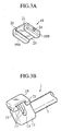
- the slip-out protective member 19 is secured to the hook segment 11 by moving the sip-out protective member 19 in a direction as shown by an arrow X in FIG. 2A and coupling the slip-out protective member 19 to the pair of lateral engagement projections 17, 17 of the hook segment 11 to allow the minute projections 15, 15 to be held in sliding engagement with the slide recesses 21, 21 of the slip-out protective member 19 such that the entrance of the U-shaped hanging recess 13 of the hook segment 11 is closed with the slip-out protective member 19, as viewed in FIG. 3B , for thereby preventing the interconnecting member 9 from disengaging from the U-shaped hanging recess 13.
- the distal ends of the pin-shaped section 7 of the vertebral connecting rod 1 are fixedly retained with the spinal implants 5, 5 anchored to the vertebral bodies 3, 3 for thereby interconnecting the vertebral bodies 3, 3 as a unitary structure.
- the interconnecting member 19 is hanged between the hook segment 11, which is located outward from and closest to one of the spinal implants 5,5, and the hooking spinal implant 25 which is anchored to the vertebral body 3 remaining adjacent to the vertebral body 3 in which one of the spinal implants 5, 5 is anchored as viewed in FIG. 1 .
- the vertebral connecting rod 1 has two functions, namely, a first function to interconnect the vertebral bodies 3, 3 spaced from one another and a second function to hang the interconnecting member 9. Consequently, even in a case where one osseous interconnecting structure employing the vertebral connecting rod 1 and another osseous interconnecting structure employing the interconnecting member 9 are consecutively located, it is unnecessary for the hooking spinal implant 25 to be located in close proximity to the spinal implant 5 which fixedly retains the vertebral connecting rod 1.
- the spinal implants can be mutually spaced from one another and do not interfere with one another, thereby avoiding plural spinal implants to be anchored in a single vertebral body to address the issues encountered in the prior art discussed above.
- slip-out protective member 19 has been described as of the type wherein the slip-out protective member 19 is brought into engagement with or disengagement from the lateral engagement projections 17, 17 in the direction as shown by the arrows X in FIG. 2A , i.e., along their longitudinal directions, a modification may be made such that at least one of the lateral engagement projections 17, 17 and downward flanges 19A, 19B of the slip-out protective member 19 is resiliently formed to provide a deformable property to allow the slip-out protective member 19 from being coupled to or uncoupled from the lateral engagement projections 17, 17 of the hooking segment 11 in a direction as shown by an arrow Y in FIG.
- the slip-out protective member 19 During coupling or uncoupling operation of the slip-out protective member 19 relative to the lateral engagement projections 17, 17, it is highly probable to need an improved operability of the slip-out protective member 19 by manipulating the same with the use of a gripping tool (not shown).
- the downward flanges 19A, 19B of the slip-out protective member 19 have engagement apertures 24, 24, respectively, with which the gripping tool is engageable to be manipulated.
- the gripping tool may be manipulated to allow the slip-out protective member 19 to be coupled to or uncoupled from the lateral engagement projections 17, 17.
- FIG. 4 shows a second preferred embodiment of a vertebral connecting rod 1A according to the present invention.
- the vertebral connecting rod 1A has at its distal end a hook segment 11A having a substantially L-shaped configuration.
- the presence of the L-shaped configuration of the hook segment 11A, formed at the distal end of the pin-shaped section 7, allows the hook segment 11A to have an engaging protrusion 11P which extends in a direction to close an entrance portion of the hook segment 11A to provide a slip-out protecting property to prevent the interconnecting member 9 from slipping out from the hook segment 11A in a more simplified fashion.
- FIG. 5 shows a third preferred embodiment of a vertebral connecting rod 1B according to the present invention.
- the distal end of the pin-shaped section 7 has a U-shaped hook segment 11B which has an entrance portion formed an engaging protrusion 11BP which extends in a direction to close the entrance portion to provide a slip-out protective property to prevent the interconnecting member 9 from slipping out from the hook segment 11B.
- the rod 1B has a spherical-shaped, convex engagement segment 27 formed at a suitable position of the pin-shaped section 7 and adapted to be engageable with a spherical-shaped, concave engagement recess formed in the spinal implant (not shown).
- the convex engagement segment 27 of the rod 1B is brought into engagement with the corresponding concave engagement recess 5' a of the spinal implant 5', allowing the rod 1B to slightly swing in an arbitrary direction.
- the hook segment 11B of the rod 1B it is possible for the hook segment 11B of the rod 1B to be directed toward a tensioned direction of the interconnecting member 9 in an increased amount of freedom while preventing the rod 1B from being dislocated from the spinal implant along the axis of the rod 1B.
- the rod 1B it is easy for the rod 1B to be directed in various directions to meet the tensioned angular direction of the interconnecting member 9 such that after the interconnecting member 9 has been hanged over the hook segment 11B of the rod 1B, the rod 1B can be readily fixed to the spinal implant by turning a stopper screw.
- the presence of the hooking segment formed at the distal end of the pin-shaped section rigidly secured by the spinal implants anchored to the vertebral bodies allows the rod to have the first function to interconnect the separated vertebral bodies and the second function to hang the interconnecting member whereby even in a case where one osseous interconnecting structure employing the rod and another osseous interconnecting structure employing the interconnecting member are consecutively located, the vertebral connecting rod and the spinal osteosynthesis device of the present invention are enabled to meet various situations without causing an implantation of the plural spinal implants in a common vertebral body.
- the presence of the convex engagement segment formed on the pin-shaped section of the rod to be engageable with the corresponding concave engagement recess formed in the spinal implant allows the rod to slightly swing in a direction to meet the tensioned direction of the interconnecting member for thereby suitably adjusting the position of the rod relative to the tensioned state of the interconnecting member.
- both of the distal segments of the rod have the respective hook segments.
Landscapes
- Health & Medical Sciences (AREA)
- Orthopedic Medicine & Surgery (AREA)
- Life Sciences & Earth Sciences (AREA)
- Neurology (AREA)
- Surgery (AREA)
- Heart & Thoracic Surgery (AREA)
- Engineering & Computer Science (AREA)
- Biomedical Technology (AREA)
- Nuclear Medicine, Radiotherapy & Molecular Imaging (AREA)
- Medical Informatics (AREA)
- Molecular Biology (AREA)
- Animal Behavior & Ethology (AREA)
- General Health & Medical Sciences (AREA)
- Public Health (AREA)
- Veterinary Medicine (AREA)
- Surgical Instruments (AREA)
- Prostheses (AREA)
Priority Applications (1)
| Application Number | Priority Date | Filing Date | Title |
|---|---|---|---|
| EP14165998.7A EP2774565A1 (de) | 2000-05-10 | 2001-06-21 | Wirbelverbindungsstange und Wirbelsäulenosteosynthesevorrichtung damit |
Applications Claiming Priority (4)
| Application Number | Priority Date | Filing Date | Title |
|---|---|---|---|
| JP2000137250A JP2001314416A (ja) | 2000-05-10 | 2000-05-10 | 骨接合具用のロッド |
| US09/880,072 US6582434B2 (en) | 2000-05-10 | 2001-06-14 | Vertebral connecting rod and spinal osteosynthesis device using the same |
| EP01114710A EP1269928A1 (de) | 2000-05-10 | 2001-06-21 | Spinale Verbindungsstange und diese benutzende Vorrichtung zur Wirbelsäulenosteosynthese |
| EP14165998.7A EP2774565A1 (de) | 2000-05-10 | 2001-06-21 | Wirbelverbindungsstange und Wirbelsäulenosteosynthesevorrichtung damit |
Related Parent Applications (1)
| Application Number | Title | Priority Date | Filing Date |
|---|---|---|---|
| EP01114710A Division EP1269928A1 (de) | 2000-05-10 | 2001-06-21 | Spinale Verbindungsstange und diese benutzende Vorrichtung zur Wirbelsäulenosteosynthese |
Publications (1)
| Publication Number | Publication Date |
|---|---|
| EP2774565A1 true EP2774565A1 (de) | 2014-09-10 |
Family
ID=27224184
Family Applications (2)
| Application Number | Title | Priority Date | Filing Date |
|---|---|---|---|
| EP01114710A Ceased EP1269928A1 (de) | 2000-05-10 | 2001-06-21 | Spinale Verbindungsstange und diese benutzende Vorrichtung zur Wirbelsäulenosteosynthese |
| EP14165998.7A Withdrawn EP2774565A1 (de) | 2000-05-10 | 2001-06-21 | Wirbelverbindungsstange und Wirbelsäulenosteosynthesevorrichtung damit |
Family Applications Before (1)
| Application Number | Title | Priority Date | Filing Date |
|---|---|---|---|
| EP01114710A Ceased EP1269928A1 (de) | 2000-05-10 | 2001-06-21 | Spinale Verbindungsstange und diese benutzende Vorrichtung zur Wirbelsäulenosteosynthese |
Country Status (3)
| Country | Link |
|---|---|
| US (1) | US6582434B2 (de) |
| EP (2) | EP1269928A1 (de) |
| JP (1) | JP2001314416A (de) |
Families Citing this family (20)
| Publication number | Priority date | Publication date | Assignee | Title |
|---|---|---|---|---|
| US7282064B2 (en) * | 2003-02-11 | 2007-10-16 | Spinefrontier Lls | Apparatus and method for connecting spinal vertebrae |
| US20050080414A1 (en) * | 2003-10-14 | 2005-04-14 | Keyer Thomas R. | Spinal fixation hooks and method of spinal fixation |
| US7967826B2 (en) | 2003-10-21 | 2011-06-28 | Theken Spine, Llc | Connector transfer tool for internal structure stabilization systems |
| ES2269957T3 (es) * | 2003-10-31 | 2007-04-01 | Spinelab Ag | Mecanismo de cierre de tornillos pediculares dpara la fijacion de varillas elasticas. |
| US7214227B2 (en) * | 2004-03-22 | 2007-05-08 | Innovative Spinal Technologies | Closure member for a medical implant device |
| EP1719468A1 (de) * | 2004-12-17 | 2006-11-08 | Zimmer GmbH | Intervertebrales Stabilisierungssystem |
| EP1957010B1 (de) * | 2005-12-06 | 2019-07-31 | Globus Medical, Inc. | Facettengelenkprothesen |
| US20070233069A1 (en) * | 2006-02-27 | 2007-10-04 | Stewart Young | Implant/support member interconnection mechanism |
| US8303628B2 (en) * | 2008-05-14 | 2012-11-06 | Dewey Jonathan M | Spinal stabilization system |
| US8876867B2 (en) * | 2009-06-24 | 2014-11-04 | Zimmer Spine, Inc. | Spinal correction tensioning system |
| AU2011276535B2 (en) | 2010-06-28 | 2015-03-12 | K2M, Inc. | Spinal stabilization system |
| US9545270B2 (en) | 2012-10-15 | 2017-01-17 | K2M, Inc. | Universal rod holder |
| US9168068B2 (en) | 2012-11-13 | 2015-10-27 | K2M, Inc. | Spinal stabilization system |
| US9186182B2 (en) | 2012-11-13 | 2015-11-17 | K2M, Inc. | Spinal stabilization system |
| US9827018B2 (en) | 2012-11-13 | 2017-11-28 | K2M, Inc. | Spinal stabilization system |
| US9801662B2 (en) | 2012-11-13 | 2017-10-31 | K2M, Inc. | Spinal stabilization system |
| US9095378B2 (en) | 2012-11-13 | 2015-08-04 | K2M, Inc. | Spinal stabilization system |
| AU2016200919B2 (en) * | 2015-02-12 | 2020-08-27 | K2M, Inc. | Spinal fixation construct and methods of use |
| US10463403B2 (en) * | 2017-07-31 | 2019-11-05 | Medos International Sarl | Systems and methods for reducing the risk of proximal junctional kyphosis using a bone anchor or other attachment point |
| US10456174B2 (en) | 2017-07-31 | 2019-10-29 | Medos International Sarl | Connectors for use in systems and methods for reducing the risk of proximal junctional kyphosis |
Citations (5)
| Publication number | Priority date | Publication date | Assignee | Title |
|---|---|---|---|---|
| WO1996014022A1 (fr) * | 1994-11-07 | 1996-05-17 | Scient'x S.A.R.L. | Systeme de fixation vertebrale |
| US5562737A (en) * | 1993-11-18 | 1996-10-08 | Henry Graf | Extra-discal intervertebral prosthesis |
| US5704936A (en) * | 1992-04-10 | 1998-01-06 | Eurosurgical | Spinal osteosynthesis device |
| FR2752719A1 (fr) * | 1996-09-04 | 1998-03-06 | Stryker France Sa | Systeme d'osteosynthese pour colonne vertebrale, a repartition de contraintes |
| US5725582A (en) * | 1992-08-19 | 1998-03-10 | Surgicraft Limited | Surgical implants |
Family Cites Families (9)
| Publication number | Priority date | Publication date | Assignee | Title |
|---|---|---|---|---|
| US5102412A (en) * | 1990-06-19 | 1992-04-07 | Chaim Rogozinski | System for instrumentation of the spine in the treatment of spinal deformities |
| FR2672202B1 (fr) * | 1991-02-05 | 1993-07-30 | Safir | Implant chirurgical osseux, notamment pour stabilisateur inter-vertebral. |
| EP0572790B1 (de) * | 1992-06-04 | 1996-02-14 | Synthes AG, Chur | Osteosynthetisches Befestigungselement |
| FR2697744B1 (fr) * | 1992-11-10 | 1995-03-03 | Fabrication Mat Orthopedique S | Instrumentation d'ostéosynthèse rachidienne par voie antérieure. |
| FR2747028B1 (fr) * | 1996-04-09 | 1998-06-26 | Stryker France Sa | Dispositif de fixation d'une tige d'osteosynthese rachidienne orientable a moyens de confirmation de blocage angulaire |
| US5776135A (en) * | 1996-12-23 | 1998-07-07 | Third Millennium Engineering, Llc | Side mounted polyaxial pedicle screw |
| FR2767263B1 (fr) * | 1997-08-13 | 1999-10-01 | Aesculap Jbs | Pince pour systeme d'osteosynthese vertebrale |
| US5989251A (en) * | 1998-06-17 | 1999-11-23 | Surgical Dynamics, Inc. | Apparatus for spinal stabilization |
| US5910142A (en) * | 1998-10-19 | 1999-06-08 | Bones Consulting, Llc | Polyaxial pedicle screw having a rod clamping split ferrule coupling element |
-
2000
- 2000-05-10 JP JP2000137250A patent/JP2001314416A/ja active Pending
-
2001
- 2001-06-14 US US09/880,072 patent/US6582434B2/en not_active Expired - Lifetime
- 2001-06-21 EP EP01114710A patent/EP1269928A1/de not_active Ceased
- 2001-06-21 EP EP14165998.7A patent/EP2774565A1/de not_active Withdrawn
Patent Citations (5)
| Publication number | Priority date | Publication date | Assignee | Title |
|---|---|---|---|---|
| US5704936A (en) * | 1992-04-10 | 1998-01-06 | Eurosurgical | Spinal osteosynthesis device |
| US5725582A (en) * | 1992-08-19 | 1998-03-10 | Surgicraft Limited | Surgical implants |
| US5562737A (en) * | 1993-11-18 | 1996-10-08 | Henry Graf | Extra-discal intervertebral prosthesis |
| WO1996014022A1 (fr) * | 1994-11-07 | 1996-05-17 | Scient'x S.A.R.L. | Systeme de fixation vertebrale |
| FR2752719A1 (fr) * | 1996-09-04 | 1998-03-06 | Stryker France Sa | Systeme d'osteosynthese pour colonne vertebrale, a repartition de contraintes |
Also Published As
| Publication number | Publication date |
|---|---|
| EP1269928A1 (de) | 2003-01-02 |
| US6582434B2 (en) | 2003-06-24 |
| JP2001314416A (ja) | 2001-11-13 |
| US20020193793A1 (en) | 2002-12-19 |
Similar Documents
| Publication | Publication Date | Title |
|---|---|---|
| EP2774565A1 (de) | Wirbelverbindungsstange und Wirbelsäulenosteosynthesevorrichtung damit | |
| EP1693012B1 (de) | Fixationsvorrichtung für die Wirbelsäule | |
| JP4005147B2 (ja) | 骨接合装置用のフック型インプラント | |
| US6860884B2 (en) | Implant for bone connector | |
| US8372119B2 (en) | Dual rod cross connectors and inserter tools | |
| JP2554853B2 (ja) | 脊椎についての相互連結装置及び保持装置 | |
| EP2413823B1 (de) | Orthopädische klemme und extensionsstab | |
| US7572282B2 (en) | Spinal fixation plates and plate extensions | |
| ES2333706T3 (es) | Conjunto y dispositivo de tornillo y barra de fijacion. | |
| US7597707B2 (en) | Pedicle screw with a closure device for the fixing of elastic rod elements | |
| EP1192910A3 (de) | Stange für Halswirbelsäule und Verbindungssystem | |
| US8795337B2 (en) | Apparatus for implementing a spinal fixation system with supplemental fixation | |
| CA2088961A1 (en) | Perpendicular rod connector for spinal fixation device | |
| WO2003099148A3 (en) | Vertebrae bone anchor and cable for coupling it to a rod | |
| ES2156527A1 (es) | Sistema de fijacion vertebral dorso-lumbar y lumbo-sacro. | |
| EP0796593A3 (de) | Verfahren und Instrumentarium für die Einsetzung eines chirurgischen Implantats | |
| CA2516791A1 (en) | Adjustable rod and connector device and method of use | |
| JP2009533088A (ja) | 脊椎接続要素を受け入れるための装置と方法 | |
| EP1138267A3 (de) | Wirbelsäulenimplantat, Antriebswerkzeug und Mutterführung | |
| CN101426438A (zh) | 用于在骨锚中固定延伸的脊柱连接构件的装置 | |
| KR20020036679A (ko) | 뼈 접합용구 및 그 연결부재 | |
| EP0947174A3 (de) | Blockierungsmechanismus zur Fixierung der Wirbelsäule | |
| EP0878170A3 (de) | Querverbindungsklemme für Wirbelsäulestäbe | |
| KR20080004472A (ko) | 래치팅 고정 플레이트 | |
| CN101460108A (zh) | 用于互连脊柱移植装配组合体中的组件的装置 |
Legal Events
| Date | Code | Title | Description |
|---|---|---|---|
| PUAI | Public reference made under article 153(3) epc to a published international application that has entered the european phase |
Free format text: ORIGINAL CODE: 0009012 |
|
| 17P | Request for examination filed |
Effective date: 20140425 |
|
| AC | Divisional application: reference to earlier application |
Ref document number: 1269928 Country of ref document: EP Kind code of ref document: P |
|
| AK | Designated contracting states |
Kind code of ref document: A1 Designated state(s): DE FR |
|
| RIN1 | Information on inventor provided before grant (corrected) |
Inventor name: ORIBE, KAZUYA Inventor name: SATO, KOJI Inventor name: KAWAKAMI, NORIAKI Inventor name: TAKAMIDO, HIROSHI Inventor name: MATSUYAMA, YUKIHIRO |
|
| R17P | Request for examination filed (corrected) |
Effective date: 20150226 |
|
| RBV | Designated contracting states (corrected) |
Designated state(s): DE FR |
|
| STAA | Information on the status of an ep patent application or granted ep patent |
Free format text: STATUS: THE APPLICATION HAS BEEN WITHDRAWN |
|
| 17Q | First examination report despatched |
Effective date: 20170228 |
|
| 18W | Application withdrawn |
Effective date: 20170316 |