EP2774573A1 - Contre-angle médical, en particulier dentaire - Google Patents
Contre-angle médical, en particulier dentaire Download PDFInfo
- Publication number
- EP2774573A1 EP2774573A1 EP13157522.7A EP13157522A EP2774573A1 EP 2774573 A1 EP2774573 A1 EP 2774573A1 EP 13157522 A EP13157522 A EP 13157522A EP 2774573 A1 EP2774573 A1 EP 2774573A1
- Authority
- EP
- European Patent Office
- Prior art keywords
- sleeve
- drive shaft
- bearing
- grip
- grip sleeve
- Prior art date
- Legal status (The legal status is an assumption and is not a legal conclusion. Google has not performed a legal analysis and makes no representation as to the accuracy of the status listed.)
- Granted
Links
Images
Classifications
-
- A—HUMAN NECESSITIES
- A61—MEDICAL OR VETERINARY SCIENCE; HYGIENE
- A61C—DENTISTRY; APPARATUS OR METHODS FOR ORAL OR DENTAL HYGIENE
- A61C1/00—Dental machines for boring or cutting ; General features of dental machines or apparatus, e.g. hand-piece design
- A61C1/08—Machine parts specially adapted for dentistry
- A61C1/18—Flexible shafts; Clutches or the like; Bearings or lubricating arrangements; Drives or transmissions
- A61C1/185—Drives or transmissions
-
- A—HUMAN NECESSITIES
- A61—MEDICAL OR VETERINARY SCIENCE; HYGIENE
- A61C—DENTISTRY; APPARATUS OR METHODS FOR ORAL OR DENTAL HYGIENE
- A61C1/00—Dental machines for boring or cutting ; General features of dental machines or apparatus, e.g. hand-piece design
- A61C1/08—Machine parts specially adapted for dentistry
- A61C1/088—Illuminating devices or attachments
-
- A—HUMAN NECESSITIES
- A61—MEDICAL OR VETERINARY SCIENCE; HYGIENE
- A61C—DENTISTRY; APPARATUS OR METHODS FOR ORAL OR DENTAL HYGIENE
- A61C1/00—Dental machines for boring or cutting ; General features of dental machines or apparatus, e.g. hand-piece design
- A61C1/08—Machine parts specially adapted for dentistry
- A61C1/12—Angle hand-pieces
Definitions
- the present invention relates to a medical, in particular dental, angle piece with a one-piece, hollow grip sleeve having a first sleeve portion and a second sleeve portion which are bent or angled to each other and with a drive train for moving a tool holder with a substantially in the first sleeve portion provided first drive shaft and a substantially provided in the second sleeve portion second drive shaft.
- the angle piece has a one-piece, hollow grip sleeve, in which a base body is received.
- the main body stores the drive shafts with their respective bearing sleeves and bearings and various media lines.
- the one-piece grip sleeve is pushed onto the base body and locked to the base body.
- a one-piece grip sleeve has, in comparison to a multi-part grip sleeve, inter alia, the advantage that no edges or interfaces are present, where dirt can get stuck or contaminants can penetrate into the elbow that no means for connecting the grip sleeve parts are needed or that the interfaces no care agents can escape from the interior of the elbow.
- the structure of the elbow from the patent US 4,278,428 however, it is complicated and time-consuming.
- the present invention is therefore an object of the invention to provide a medical, in particular dental, elbow, while maintaining a one-piece, hollow grip sleeve (with a first sleeve portion and a second sleeve portion, which are bent or angled to each other) and the associated advantages simpler structure and less expensive to produce.
- the medical, in particular dental, angle piece comprising: A one-piece, hollow grip sleeve with a head sleeve-side end collar, a connection-side end collar, an inner peripheral wall and with a first sleeve portion and a second sleeve portion, which are bent or angled to each other, one of the A drive train for moving the tool holder with a substantially provided in the first sleeve portion first drive shaft and a substantially provided in the second sleeve portion second drive shaft, wherein the first drive shaft in a first Bearing sleeve and the second drive shaft in a second bearing sleeve is provided, a first stop, which is intended to determine the position of the first drive shaft in the first sleeve portion and a second stop, which is intended to determine the position of the second drive shaft in the second sleeve portion, wherein the first and the second stop at least On
- the first and second stops thus define or determine the position of the drive shafts in the elbow, in particular the axial (relative to the longitudinal axis (s) of the elbow) position of the drive shafts.
- the two stops in particular also form a guide for the drive shafts and / or the bearing sleeves in which the drive shafts are mounted.
- the one-piece grip sleeve in particular its end collars or inner peripheral wall or integrally formed therewith bearing element, as a supporting element or bearing element, preferably additionally as a guide element for at least the drive train and / or the drive shafts and / or their bearing sleeves, and not only forms an envelope for the main body supporting the drive shafts and the other components, as is known from the prior art.
- the formation of the one-piece grip sleeve as a position of the drive shaft defining element and / or as a supporting element or bearing element is preferably defined by the fact that at least one stop direct or direct contact with at least one bearing sleeve which supports a drive shaft, in particular with a the bearing sleeve provided counter-stop, is provided. It is thus determined by direct contact of the counter-stop with the stop at least the position, in particular the axial position, at least one drive shaft in a sleeve portion.
- the first drive shaft and / or the first bearing sleeve and / or the first sleeve section is / are defined in particular by being arranged closer to the head sleeve than the second drive shaft and / or the second bearing sleeve and / or the second sleeve section.
- the first and / or the second stop are preferably formed in one piece or inseparable with the grip sleeve.
- the first and / or the second stop and / or the Counter-stop is / are formed, for example, as a shoulder, recess, projection, recess, collar or step.
- the first and / or the second stop projects, for example, from the inner peripheral wall of the one-piece grip sleeve into the interior of the hollow, one-piece grip sleeve.
- At least one of the stops is circular or annular in shape and / or extends, for example, along the inner peripheral wall of the one-piece grip sleeve, in particular with a substantially constant radius about a central axis of the first or second sleeve portion.
- the counter stop extends in a circular arc or ring around the outer wall of the bearing sleeve, in particular with a substantially constant radius about a central axis of the bearing sleeve.
- the counter-stop is in particular connected in one piece or inseparably connected to the bearing sleeve and / or produced.
- a medical or dental handle element is referred to in a known manner, which has a grip sleeve and an adjoining head sleeve, wherein the grip sleeve is bent or angled and thus has two sleeve portions which are bent or angled to each other. Due to the bent or angled arrangement of the two sleeve sections, the angle piece and / or the one-piece grip sleeve (in the region of the bend or angle) has a concave upper side and a convex lower side.
- the head sleeve and / or the tool holder received therein have a longitudinal axis (wherein the longitudinal axis of the tool holder is in particular equal to an axis of rotation of a rotatable tool holder), which extends from the side with the receiving opening to the receiving opening opposite side of the head sleeve.
- This longitudinal axis encloses an angle of about 90 ° with the first central axis of the first sleeve portion.
- the grip sleeve In the interior of the grip sleeve are preferably next to the drive train, in particular the two drive shafts and their bearing sleeves, other components, for example one or more media or fluid lines and / or at least one light guide and / or at least one light source and / or at least one electrical (signal ) line and / or at least one sensor arranged. These components are arranged in particular in intermediate spaces between the grip sleeve, in particular its inner peripheral wall, and the drive train, in particular the bearing sleeves.
- the two drive shafts are connected to each other in particular by two gears, wherein in each case a gear is provided on a drive shaft.
- the two drive shafts are interconnected by a transmission, for example by a reduction or transmission gear.
- a further gear is provided on the head sleeve-side end of the first drive shaft, which meshes with a gear connected to the tool holder gear.
- at least one stop is provided to fix the position of at least one of the above-mentioned gears and / or at least part of the gear in the grip sleeve and / or the position of a gear with respect to another gear.
- At least one element for axial and / or radial bearings and / or fastening to the one-piece grip sleeve in particular on the inner peripheral wall of the one-piece grip sleeve or on the integrally formed therewith bearing element, and / or an element for holding , Guiding, passage or passing a media or fluid line or a light guide provided.
- Such elements may include, for example, a projection, a recess, a receptacle, a recess, a groove, a shoulder, a recess, a stop, a flange, etc.
- a clamping element which defines the axial and / or radial position of a drive shaft in a sleeve section by direct contact with a stop on the inner peripheral wall of the one-piece grip sleeve or on the integrally formed therewith bearing element.
- the tensioning element is, for example, detachably connectable to a drive shaft, in particular to a bearing sleeve receiving the drive shaft.
- the clamping element is formed for example as a threaded element, in particular as a nut, with an internal thread which can be screwed onto an external thread of a bearing sleeve.
- the head sleeve is detachable from the grip sleeve, wherein the tensioning element is also provided to brace the head sleeve with the grip sleeve.
- the clamping element is advantageously both for fixing the axial and / or radial position of a drive shaft in the one-piece grip sleeve and the connection and attachment of the head sleeve with the grip sleeve, so that no separate connection device is necessary.
- the first bearing sleeve is designed as a connecting element for connecting and bracing the head sleeve with the grip sleeve.
- the head sleeve is clamped to the grip sleeve by connecting the clamping element with the bearing sleeve or by screwing the clamping element on the bearing sleeve and more preferably by the direct contact of the clamping element produced with the stop on the inner peripheral wall of the one-piece grip sleeve.
- the head sleeve is detachably connectable to the first drive shaft and / or the first bearing sleeve, preferably by means of a connecting device.
- the connecting device comprises, for example, a screw, plug or latching device on the head sleeve, in particular on a sleeve-like extension of the head sleeve, and on the bearing sleeve, in particular on a head sleeve-side end of the bearing sleeve.
- the grip sleeve has at its head sleeve-side end an opening through which the first drive shaft and / or the first bearing sleeve which is in particular connected to the head sleeve / and which form a structural unit, is inserted into the grip sleeve / are.
- the sleeve-like extension of the head sleeve is insertable through the opening at the head sleeve-side end of the grip sleeve and / or in the hollow, one-piece grip sleeve receivable.
- a stop for the head sleeve-side end or the head sleeve-side end collar or stop the one-piece grip sleeve is provided on the head sleeve.
- the grip sleeve has at its connection-side end an opening through which the tensioning element, in particular the threaded element, preferably the nut, can be inserted into the grip sleeve.
- the clamping element is connectable to the inserted into the hollow grip sleeve first bearing sleeve of the first drive shaft, which is particularly preferred and as already described above, the first bearing sleeve with the head sleeve in the grip sleeve is clamped.
- the clamping element is particularly preferably connected to the bearing sleeve such that it bears against a stop on the inner peripheral wall of the grip sleeve, in particular of the first sleeve portion, whereby, as also already described above, the position of the first drive shaft and the bearing sleeve in the first sleeve portion can be fixed, the first drive shaft in the one-piece grip sleeve is fastened and the head sleeve is clamped to the one-piece grip sleeve.
- the tensioning element is disposed entirely within the inner circumferential wall of the hollow grip sleeve.
- the bearing element formed integrally with the first sleeve section or the bearing element formed integrally with the second sleeve section extends from the inner peripheral wall of the hollow grip sleeve into the interior of the grip sleeve and supports or positions, preferably radially, in particular at least one, inside the angle piece provided component, for example, a bearing sleeve of a drive shaft, a media or fluid line, a light guide and / or an electrical conductor.
- a bearing element allows reliable storage of a component arranged in the angle.
- the one-piece formed with the grip sleeve bearing element is formed, for example, as projecting from the inner peripheral wall into the interior of the one-piece grip sleeve extension or projection.
- the longitudinal axis of the head sleeve and / or the tool holder received therein encloses an angle of approximately 90 ° with the first central axis of the first sleeve portion.
- At least one bearing sleeve of a drive shaft has an outer shell with an inner bore, wherein the inner bore is closed by a closure part and wherein in the closure part an opening is provided, through which a drive shaft protrudes.
- a drive shaft and / or a gear is mounted in the bearing sleeve and another drive shaft and / or another gear protrudes through the opening, so that in particular the two drive shafts and / or gears are interconnected or mesh with each other.
- the bearing sleeve is cup-shaped.
- the Inner diameter of the opening smaller than the inner diameter of the inner bore of the bearing sleeve.
- a further bearing sleeve in particular the first bearing sleeve which supports the first drive shaft, and / or a component connected to the further bearing sleeve
- the clamping element which determines the position of a drive shaft by direct contact with a stop provided.
- a receptacle for the sealing element is provided on the clamping element, in particular on its end facing the bearing sleeve with the closure part end.
- a method for producing an angle piece comprises the steps of inserting the first drive shaft, preferably with the first bearing sleeve, into the angle piece, wherein the first stop, in particular the head sleeve side end stop, determines the position of the first drive shaft in the first sleeve portion and in that the second drive shaft, preferably with the second bearing sleeve, is inserted into the angle piece, the second stop determining the position of the second drive shaft in the second sleeve section.
- the first drive shaft and / or the first bearing sleeve is or is connected to the head sleeve prior to insertion into the elbow.
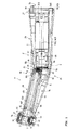
- the first central axis 12A of the first sleeve portion 2A and the second center axis 12B of the second sleeve portion 2B include an obtuse angle of, in particular, about 165 ° -170 °.
- the bend or angle 20 is located approximately in the middle of the elongated, one-piece grip sleeve 2. Due to the bending or angulation 20, the one-piece grip sleeve 2 (in the region of bending or angulation 20) has a concave top 19 and a convex bottom 21. Preferably, the components are inside the grip sleeve 2 only through one of the two openings 13, 17 (see FIG.
- the head sleeve 4 further comprises at least one bearing 29 for rotatably supporting the tool holder 5, a tool receiving opening 28 for inserting and removing the tool into the tool holder 5, a fluid dispenser 30 for dispensing at least one fluid to a treatment site, preferably around the tool receiving opening 28 arranged, and a release device for releasing a tool from the tool holder 5, which has for actuating, for example, a button or a pressure cap 31.
- the head sleeve 4 is releasably connectable to the one-piece grip sleeve 2, wherein the head sleeve 4 has a sleeve-like extension 32 which is inserted into the grip sleeve 2, in particular in the first sleeve portion 2A.
- the head sleeve 4 further includes a longitudinal axis 22 extending from the concave top 19 of the elbow 1 to the convex bottom 21.
- This longitudinal axis 22 is ident or congruent to a rotational axis of the rotatable tool holder 5.
- This longitudinal or rotational axis 22 closes with the first central axis 12A of the first sleeve portion 2A at an angle of about 90 °.
- the longitudinal or rotational axis 22 further includes, with the axis of rotation 16A of the first drive shaft 6A, an angle greater than 90 °, in particular between 91 ° and 93 °.
- the drive train 6 for moving the tool holder 5 in motion comprises a first drive shaft 6A arranged essentially in the first sleeve section 2A and a second drive shaft 6B arranged substantially in the second sleeve section 2B.
- the first drive shaft 6A is received in a first bearing sleeve 7A and the second drive shaft 6B is received in a second bearing sleeve 7B.
- the second drive shaft 6B preferably comprises two shaft parts, which are displaceable relative to each other.
- one shaft part comprises a driver 36B of a coupling device 36 and the other shaft part the gear of the transmission 33.
- connection-side end 2 "of the grip sleeve 2 via a coupling device 36 provided there, which inter alia a coupling tube 36A for receiving a connection part of a drive unit, for example an electric motor, and a in the coupling tube 36A arranged driver 36B at the end of the second drive shaft 6B comprises.
- a coupling device 36 provided there, which inter alia a coupling tube 36A for receiving a connection part of a drive unit, for example an electric motor, and a in the coupling tube 36A arranged driver 36B at the end of the second drive shaft 6B comprises.
- the two drive shafts 6A, 6B and / or the two bearing sleeves 7A, 7B are also arranged at an angle to one another.
- their rotational or longitudinal axes 16A, 16B enclose an angle of about 155 ° - 175 °, in particular of about 160 ° - 170 °.
- the elbow 1 includes at least one first stopper 8A or 8C provided to fix the position of the first drive shaft 6A in the first sleeve portion 2A, and at least one second stopper 8B or 8D provided, the position of the second drive shaft 6B in the second sleeve portion 2B.
- the second stopper 8B is provided, for example, on the inner peripheral wall 3 of the second sleeve portion 2B, and is preferably formed as a ring-shaped or circular shoulder extending along the inner peripheral wall 3 (see also FIG FIG. 2 ).
- the second stopper 8D is provided in particular on the connection-side end collar 2D and / or formed by it.
- a counter-abutment 10 is provided (see also FIG. 4 ), which fixes the position of the second drive shaft 6B in the sleeve portion 2B by direct contact with a stopper 8B, 8D, specifically, fixes the axial position (with respect to the central axis 12B) of the second drive shaft 6B in the sleeve portion 2B.
- the second bearing sleeve 7B and the second drive shaft 6B are thus, in particular as a structural unit, axially inserted through the opening 13 of the angle piece 1 in the one-piece grip sleeve 2 until the counter-stop 10 contacts the second stop 8B, 8D.
- At least one stop 8A-8D has a stop face facing the connection-side end 2 "of the grip sleeve 2, so that the component contacting the at least one stop 8A-8D, in particular the counter-stop 10 or the tensioning element 11, passes through the connection-side end 2" in FIG the grip sleeve 2 can be inserted and, in particular, subsequently brought into contact with the at least one stop 8A-8D.
- the first stop 8A is, as in particular from FIG. 2 can be seen, formed in part from the inner peripheral wall 3 of the first sleeve portion 2A (in particular in the region of the concave upper side 19) and partly from a one-piece with the first sleeve portion 2A formed bearing element 9 or provided on these parts.
- the bearing element 9 described in more detail below comprises a receptacle or bore 9A for receiving and / or supporting at least a part of the first bearing sleeve 7A and / or the first drive shaft 6A.
- the first stop 8A is preferably provided at the end of the bearing element 9, in particular the receptacle 9A, facing away from the head sleeve.
- the first stop 8A is preferably formed as a ring or circular shoulder or step.
- the first stop 8C is provided in particular on the head sleeve-side end collar 2C and / or formed by it.
- the first stopper 8C is provided to fix the position of the first drive shaft 6A in the sleeve portion 2A, specifically, to fix the axial position (with respect to the central axis 12A) of the first drive shaft 6A in the sleeve portion 2A.
- a counter-stop is provided which contacts the first stop or head sleeve-side stopper 8C.
- a tensioning element 11 which fixes the position of the first drive shaft 6A in the sleeve section 2A by direct contact with the stop 8A, in particular additionally or alternatively to the stop 8C.
- the tensioning element 11 comprises in particular a nut with an internal thread which can be screwed onto an external thread of the first bearing sleeve 7A.
- the tensioning element 11 can be screwed onto the first bearing sleeve 7A until it contacts the first stop 8A.
- the first drive shaft 6A is, preferably in common with the first bearing sleeve 7A, through the opening 17 on the head sleeve-side end 2 'and the clamping element 11 can be inserted through the connection-side end 2 "in the one-piece grip sleeve 2.
- the clamping element 11 is in particular substantially first parallel to the axis to the second central axis 12B through the second sleeve portion 2B, then tilted inside the angle 1 and then moved substantially axially parallel to the first central axis 12A and screwed onto the bearing sleeve 7 A.
- the angle 1, in particular the interior of the grip 2 is preferably dimensioned such that the tension element 11 substantially first axially parallel to the second central axis 12B is movable by the second sleeve portion 2B, is pivotable in the interior of the angle piece 1 and substantially axially parallel to the first central axis 12A and can be screwed onto the bearing sleeve 7 A.
- the first bearing sleeve 7A and the clamping element 11 are then in the Inn Eren the one-piece grip sleeve 2 connected to each other.
- the clamping element 11 is further provided for bracing the detachable from the one-piece grip sleeve 2 head sleeve 4 with the grip sleeve 2.
- a connecting element between the clamping element 11 and the head sleeve 4 to the first bearing sleeve 7A is provided, which is connected to the head sleeve 4, preferably releasably connected.
- the tensioning element 11 By connecting or screwing the clamping element 11 on the first bearing sleeve 7A, in particular by the contact between the first stop 8A and the clamping element 11, the head sleeve 4 with the one-piece grip sleeve 2, in particular with the first sleeve portion 2A, connectable, positionable or braced , the tensioning element 11 thus braces or fixes the first drive shaft 6A and / or the first bearing sleeve 7A in the one-piece grip sleeve 2.
- a light guide 15 or at least one media or fluid conduit 39 for delivering a fluid to the treatment site associated with the fluid delivery device 30 is connected, or at least one electrical conductor.
- At least one of these components, for example the light guide 15 or the fluid line 39, is arranged closer to the convex underside 21 of the grip sleeve 2 than the concave upper side 19 of the grip sleeve 2, in particular in the region of the bend or angle 20 of the grip sleeve 2.
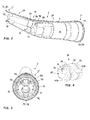
- bearing element 9 integrally with the grip sleeve 2, for example, the first sleeve portion 2A, formed bearing element 9 is particularly in the FIGS. 2 and 3 good to see.
- the bearing element 9 extends from the inner peripheral wall 3 of the hollow grip sleeve 2 into an inner space 14 of the grip sleeve 2.
- the bearing element 9 is, for example, a substantially disc-shaped element with a side surface facing the head sleeve-side end 2 ', one of the connection-side
- the bearing element 9 is in particular integrally or permanently connected to the inner circumferential wall 3 at least over part of its outer circumference or outer edge.
- the bearing element 9 is provided in particular for supporting at least one component provided inside the angle piece 1, for example a drive shaft 6A, a bearing sleeve 7A of a drive shaft 6A, a media or fluid line 39, a light guide 15 and / or an electrical conductor or record.
- the bearing element 9 is particularly preferably provided to store or fix a component provided in the interior of the angle piece 1 radially (with respect to the first central axis 12A) in the angle piece 1, in particular the first drive shaft 6A and / or the bearing sleeve 7A radially Store or fix and thus in particular to ensure a reliable engagement of the gears of the transmission 33.
- At least one receptacle, recess or bore 9A, 9B, 9C is preferably provided on the bearing element 9, in which the component can be arranged, accommodated and / or stored.
- at least one of the bores 9A, 9B, 9C is formed closed at its periphery.
- the two holes 9B are provided for receiving a respective media or fluid line 39.
- at least part of the first stop 8A is provided on the bearing element 9, preferably on the opening 9A for receiving the first bearing sleeve 7A.
- at least part of the clamping element 11 in the bearing element 9, preferably in the opening 9A can be accommodated.
- the bearing element 9, in particular the stop 8A, for contact with the clamping element 11 is formed.
- the FIG. 4 shows the second bearing sleeve 7B for supporting the second drive shaft 6B and in particular provided on the second drive shaft 6B parts of the transmission 33.
- the second bearing sleeve 7B comprises a, preferably substantially cylindrical, outer casing 23 with an inner bore 24, the inner bore 24 being closed by a closure part 25.
- the closure member 25 is preferably a substantially disc-shaped member.
- the closure part 25 is arranged either at one end of the second bearing sleeve 7B, in particular at the head sleeve-side end of the second bearing sleeve 7B, or between the two ends of the second bearing sleeve 7B, in particular in the inner bore 24.
- the closure part 25 is preferably formed as a wall element at one end of the second bearing sleeve 7B, so that the second bearing sleeve 7B in particular has a cup-shaped shape.
- the sealing element 27 is accommodated in a receptacle, for example a groove, which is provided, for example, on the second bearing sleeve 7B, in particular on its head sleeve-side end and / or on the closure part 25.
- the receptacle for the sealing element 27 is provided on the first bearing sleeve 7A or on a component connected thereto, in particular on the tensioning element 11.
- the first bearing sleeve 7A or the clamping element 11 has at one end, in particular at the second layer sleeve 7B facing the end, an opening through which the first drive shaft 6A protrudes.
- the receptacle for the sealing element 27 and / or the sealing element 27 is arranged around this opening. The sealing element 27 thus radially surrounds the opening and / or the first drive shaft 6A with respect to the axis 16A.
- At least one receptacle or recess 40A, 40B for the passage, reception or storage of a media or fluid line 39 or a light guide 15 is preferably provided on the outer side or the outer jacket of the second bearing sleeve 7B in addition to the counter-abutment 10 already described above.
- the receptacles 40A, 40B extend axially along the longitudinal axis of the second bearing sleeve 7B or the second central axis 12B.
- a plurality of projections 42, recesses or grooves radially surrounding the second bearing sleeve 7B can be seen on the outer side or the outer jacket of the second bearing sleeve 7B, for example for supporting or radially positioning the second bearing sleeve 7B on the one-piece grip sleeve 2, in particular their inner peripheral wall 3, are provided.
- angle piece 1 is thus defined with respect to the positioning and support of the drive shafts 6A, 6B particularly preferably characterized in that the axial position of the first drive shaft 6A in the first sleeve portion 2A through the first stop 8C, the axial position of the second drive shaft 6B in the second sleeve portion 2B by the second stopper 8B and the radial bearing or positioning of the first drive shaft 6A in the first sleeve portion 2A by the bearing element 9, in particular the bore 9A, is formed.
- the invention is not limited to the described embodiments, but includes all embodiments that apply or include the principle, analogous principle of operation of the invention. Furthermore, all features of all described and illustrated embodiments can be combined.
Landscapes
- Health & Medical Sciences (AREA)
- Oral & Maxillofacial Surgery (AREA)
- Dentistry (AREA)
- Epidemiology (AREA)
- Life Sciences & Earth Sciences (AREA)
- Animal Behavior & Ethology (AREA)
- General Health & Medical Sciences (AREA)
- Public Health (AREA)
- Veterinary Medicine (AREA)
- Dental Tools And Instruments Or Auxiliary Dental Instruments (AREA)
Priority Applications (2)
| Application Number | Priority Date | Filing Date | Title |
|---|---|---|---|
| EP17151590.1A EP3175816B1 (fr) | 2013-03-04 | 2013-03-04 | Contra-angle médical, en particulier dentaire |
| EP13157522.7A EP2774573B1 (fr) | 2013-03-04 | 2013-03-04 | Contre-angle médical, en particulier dentaire |
Applications Claiming Priority (1)
| Application Number | Priority Date | Filing Date | Title |
|---|---|---|---|
| EP13157522.7A EP2774573B1 (fr) | 2013-03-04 | 2013-03-04 | Contre-angle médical, en particulier dentaire |
Related Child Applications (2)
| Application Number | Title | Priority Date | Filing Date |
|---|---|---|---|
| EP17151590.1A Division EP3175816B1 (fr) | 2013-03-04 | 2013-03-04 | Contra-angle médical, en particulier dentaire |
| EP17151590.1A Division-Into EP3175816B1 (fr) | 2013-03-04 | 2013-03-04 | Contra-angle médical, en particulier dentaire |
Publications (2)
| Publication Number | Publication Date |
|---|---|
| EP2774573A1 true EP2774573A1 (fr) | 2014-09-10 |
| EP2774573B1 EP2774573B1 (fr) | 2017-05-03 |
Family
ID=47779953
Family Applications (2)
| Application Number | Title | Priority Date | Filing Date |
|---|---|---|---|
| EP17151590.1A Active EP3175816B1 (fr) | 2013-03-04 | 2013-03-04 | Contra-angle médical, en particulier dentaire |
| EP13157522.7A Active EP2774573B1 (fr) | 2013-03-04 | 2013-03-04 | Contre-angle médical, en particulier dentaire |
Family Applications Before (1)
| Application Number | Title | Priority Date | Filing Date |
|---|---|---|---|
| EP17151590.1A Active EP3175816B1 (fr) | 2013-03-04 | 2013-03-04 | Contra-angle médical, en particulier dentaire |
Country Status (1)
| Country | Link |
|---|---|
| EP (2) | EP3175816B1 (fr) |
Citations (4)
| Publication number | Priority date | Publication date | Assignee | Title |
|---|---|---|---|---|
| EP0029863A1 (fr) * | 1979-11-29 | 1981-06-10 | Siemens Aktiengesellschaft | Instrument à main dentaire |
| US4278428A (en) | 1978-12-22 | 1981-07-14 | Siemens Aktiengesellschaft | Dental handpiece |
| EP1709933A2 (fr) * | 2005-04-07 | 2006-10-11 | Kaltenbach & Voigt GmbH | Pièce à main médicale avec axe formant un angle |
| DE102011075670A1 (de) * | 2011-05-11 | 2012-11-15 | Kaltenbach & Voigt Gmbh | Zahnärztliches Handinstrument mit länglicher Griffhülse |
Family Cites Families (1)
| Publication number | Priority date | Publication date | Assignee | Title |
|---|---|---|---|---|
| JP5323422B2 (ja) * | 2008-08-21 | 2013-10-23 | 株式会社長田中央研究所 | 治療用モータ |
-
2013
- 2013-03-04 EP EP17151590.1A patent/EP3175816B1/fr active Active
- 2013-03-04 EP EP13157522.7A patent/EP2774573B1/fr active Active
Patent Citations (4)
| Publication number | Priority date | Publication date | Assignee | Title |
|---|---|---|---|---|
| US4278428A (en) | 1978-12-22 | 1981-07-14 | Siemens Aktiengesellschaft | Dental handpiece |
| EP0029863A1 (fr) * | 1979-11-29 | 1981-06-10 | Siemens Aktiengesellschaft | Instrument à main dentaire |
| EP1709933A2 (fr) * | 2005-04-07 | 2006-10-11 | Kaltenbach & Voigt GmbH | Pièce à main médicale avec axe formant un angle |
| DE102011075670A1 (de) * | 2011-05-11 | 2012-11-15 | Kaltenbach & Voigt Gmbh | Zahnärztliches Handinstrument mit länglicher Griffhülse |
Also Published As
| Publication number | Publication date |
|---|---|
| EP3175816B1 (fr) | 2019-02-27 |
| EP2774573B1 (fr) | 2017-05-03 |
| EP3175816A1 (fr) | 2017-06-07 |
Similar Documents
| Publication | Publication Date | Title |
|---|---|---|
| DE3603344C2 (fr) | ||
| DE3500444C2 (de) | Vorrichtung zum Einführen eines Endoskops oder eines chirurgischen Werkzeugs in Körperhöhlen mit einer Zufuhr für ein Spülmedium und einer Absaugung für dieses Spülmedium | |
| DE10065232C2 (de) | Implantat zum Einsetzen zwischen Wirbelkörper sowie Operationsinstrument zur Handhabung des Implantats | |
| DE60123749T2 (de) | Endoskop mit reinigungsvorrichtung für beobachtungsfenster | |
| DE69412552T2 (de) | Medizinisches Instrument zur Behandlung von Sinusitis | |
| DE2938882C2 (de) | Lösbare Kupplung für einen schlauchförmigen Versorgungsanschluß eines Endoskops | |
| DE19859155C2 (de) | Endoskop mit einer Koppeleinrichtung (Video-Coupler) zum Anschluß einer Video-Kamera | |
| DE3802307C2 (fr) | ||
| EP1714606B1 (fr) | Endoscope | |
| EP0369043A1 (fr) | Pièce à main dentaire pourvue de moyens qui permettent une connexion compatible avec divers types d'accouplement rotatif | |
| DE102015113018A1 (de) | Endoskopkopf | |
| EP1900337B1 (fr) | Pièce à main médicale ou dentaire dotée d'une section arrière et avant | |
| DE102013108295B4 (de) | Reinigungsvorrichtung | |
| EP2130485B1 (fr) | Instrument médical | |
| DE202006017173U1 (de) | Uretero-Renoskop | |
| EP2029041B1 (fr) | Pièce à main, en particulier pour applications médicales utilisant un laser | |
| EP3175816B1 (fr) | Contra-angle médical, en particulier dentaire | |
| EP2522297B1 (fr) | Instrument manuel dentaire doté d'une poignée longitudinale | |
| DE4221403C2 (de) | Ärztliches oder zahnärztliches Behandlungsinstrument mit einem angetriebenem Behandlungswerkzeug | |
| DE202004014828U1 (de) | Endoskopisches Instrument | |
| WO2010009720A1 (fr) | Endoscope commandable | |
| DE10107156B4 (de) | Vorrichtung zur therapeutischen Behandlung in Nasennebenhöhlen | |
| WO2004032732A1 (fr) | Resectoscope a arbre externe pouvant etre decouple | |
| EP4358819A1 (fr) | Système d'endoscope | |
| DE3834156A1 (de) | Medizinisches endoskop |
Legal Events
| Date | Code | Title | Description |
|---|---|---|---|
| PUAI | Public reference made under article 153(3) epc to a published international application that has entered the european phase |
Free format text: ORIGINAL CODE: 0009012 |
|
| 17P | Request for examination filed |
Effective date: 20140117 |
|
| AK | Designated contracting states |
Kind code of ref document: A1 Designated state(s): AL AT BE BG CH CY CZ DE DK EE ES FI FR GB GR HR HU IE IS IT LI LT LU LV MC MK MT NL NO PL PT RO RS SE SI SK SM TR |
|
| AX | Request for extension of the european patent |
Extension state: BA ME |
|
| 17Q | First examination report despatched |
Effective date: 20150515 |
|
| RIC1 | Information provided on ipc code assigned before grant |
Ipc: A61C 1/12 20060101ALI20160818BHEP Ipc: A61C 1/18 20060101AFI20160818BHEP |
|
| GRAP | Despatch of communication of intention to grant a patent |
Free format text: ORIGINAL CODE: EPIDOSNIGR1 |
|
| STAA | Information on the status of an ep patent application or granted ep patent |
Free format text: STATUS: GRANT OF PATENT IS INTENDED |
|
| INTG | Intention to grant announced |
Effective date: 20161201 |
|
| GRAJ | Information related to disapproval of communication of intention to grant by the applicant or resumption of examination proceedings by the epo deleted |
Free format text: ORIGINAL CODE: EPIDOSDIGR1 |
|
| STAA | Information on the status of an ep patent application or granted ep patent |
Free format text: STATUS: EXAMINATION IS IN PROGRESS |
|
| GRAJ | Information related to disapproval of communication of intention to grant by the applicant or resumption of examination proceedings by the epo deleted |
Free format text: ORIGINAL CODE: EPIDOSDIGR1 |
|
| GRAP | Despatch of communication of intention to grant a patent |
Free format text: ORIGINAL CODE: EPIDOSNIGR1 |
|
| GRAJ | Information related to disapproval of communication of intention to grant by the applicant or resumption of examination proceedings by the epo deleted |
Free format text: ORIGINAL CODE: EPIDOSDIGR1 |
|
| GRAP | Despatch of communication of intention to grant a patent |
Free format text: ORIGINAL CODE: EPIDOSNIGR1 |
|
| GRAR | Information related to intention to grant a patent recorded |
Free format text: ORIGINAL CODE: EPIDOSNIGR71 |
|
| GRAS | Grant fee paid |
Free format text: ORIGINAL CODE: EPIDOSNIGR3 |
|
| STAA | Information on the status of an ep patent application or granted ep patent |
Free format text: STATUS: GRANT OF PATENT IS INTENDED |
|
| INTC | Intention to grant announced (deleted) | ||
| INTG | Intention to grant announced |
Effective date: 20170125 |
|
| GRAA | (expected) grant |
Free format text: ORIGINAL CODE: 0009210 |
|
| STAA | Information on the status of an ep patent application or granted ep patent |
Free format text: STATUS: THE PATENT HAS BEEN GRANTED |
|
| AK | Designated contracting states |
Kind code of ref document: B1 Designated state(s): AL AT BE BG CH CY CZ DE DK EE ES FI FR GB GR HR HU IE IS IT LI LT LU LV MC MK MT NL NO PL PT RO RS SE SI SK SM TR |
|
| REG | Reference to a national code |
Ref country code: GB Ref legal event code: FG4D Free format text: NOT ENGLISH |
|
| REG | Reference to a national code |
Ref country code: AT Ref legal event code: REF Ref document number: 889104 Country of ref document: AT Kind code of ref document: T Effective date: 20170515 Ref country code: CH Ref legal event code: EP |
|
| REG | Reference to a national code |
Ref country code: IE Ref legal event code: FG4D Free format text: LANGUAGE OF EP DOCUMENT: GERMAN |
|
| REG | Reference to a national code |
Ref country code: DE Ref legal event code: R096 Ref document number: 502013007118 Country of ref document: DE |
|
| REG | Reference to a national code |
Ref country code: NL Ref legal event code: MP Effective date: 20170503 |
|
| REG | Reference to a national code |
Ref country code: LT Ref legal event code: MG4D |
|
| PG25 | Lapsed in a contracting state [announced via postgrant information from national office to epo] |
Ref country code: NO Free format text: LAPSE BECAUSE OF FAILURE TO SUBMIT A TRANSLATION OF THE DESCRIPTION OR TO PAY THE FEE WITHIN THE PRESCRIBED TIME-LIMIT Effective date: 20170803 Ref country code: ES Free format text: LAPSE BECAUSE OF FAILURE TO SUBMIT A TRANSLATION OF THE DESCRIPTION OR TO PAY THE FEE WITHIN THE PRESCRIBED TIME-LIMIT Effective date: 20170503 Ref country code: GR Free format text: LAPSE BECAUSE OF FAILURE TO SUBMIT A TRANSLATION OF THE DESCRIPTION OR TO PAY THE FEE WITHIN THE PRESCRIBED TIME-LIMIT Effective date: 20170804 Ref country code: LT Free format text: LAPSE BECAUSE OF FAILURE TO SUBMIT A TRANSLATION OF THE DESCRIPTION OR TO PAY THE FEE WITHIN THE PRESCRIBED TIME-LIMIT Effective date: 20170503 Ref country code: HR Free format text: LAPSE BECAUSE OF FAILURE TO SUBMIT A TRANSLATION OF THE DESCRIPTION OR TO PAY THE FEE WITHIN THE PRESCRIBED TIME-LIMIT Effective date: 20170503 Ref country code: FI Free format text: LAPSE BECAUSE OF FAILURE TO SUBMIT A TRANSLATION OF THE DESCRIPTION OR TO PAY THE FEE WITHIN THE PRESCRIBED TIME-LIMIT Effective date: 20170503 |
|
| PG25 | Lapsed in a contracting state [announced via postgrant information from national office to epo] |
Ref country code: NL Free format text: LAPSE BECAUSE OF FAILURE TO SUBMIT A TRANSLATION OF THE DESCRIPTION OR TO PAY THE FEE WITHIN THE PRESCRIBED TIME-LIMIT Effective date: 20170503 Ref country code: IS Free format text: LAPSE BECAUSE OF FAILURE TO SUBMIT A TRANSLATION OF THE DESCRIPTION OR TO PAY THE FEE WITHIN THE PRESCRIBED TIME-LIMIT Effective date: 20170903 Ref country code: SE Free format text: LAPSE BECAUSE OF FAILURE TO SUBMIT A TRANSLATION OF THE DESCRIPTION OR TO PAY THE FEE WITHIN THE PRESCRIBED TIME-LIMIT Effective date: 20170503 Ref country code: RS Free format text: LAPSE BECAUSE OF FAILURE TO SUBMIT A TRANSLATION OF THE DESCRIPTION OR TO PAY THE FEE WITHIN THE PRESCRIBED TIME-LIMIT Effective date: 20170503 Ref country code: PL Free format text: LAPSE BECAUSE OF FAILURE TO SUBMIT A TRANSLATION OF THE DESCRIPTION OR TO PAY THE FEE WITHIN THE PRESCRIBED TIME-LIMIT Effective date: 20170503 Ref country code: LV Free format text: LAPSE BECAUSE OF FAILURE TO SUBMIT A TRANSLATION OF THE DESCRIPTION OR TO PAY THE FEE WITHIN THE PRESCRIBED TIME-LIMIT Effective date: 20170503 Ref country code: BG Free format text: LAPSE BECAUSE OF FAILURE TO SUBMIT A TRANSLATION OF THE DESCRIPTION OR TO PAY THE FEE WITHIN THE PRESCRIBED TIME-LIMIT Effective date: 20170803 |
|
| PG25 | Lapsed in a contracting state [announced via postgrant information from national office to epo] |
Ref country code: SK Free format text: LAPSE BECAUSE OF FAILURE TO SUBMIT A TRANSLATION OF THE DESCRIPTION OR TO PAY THE FEE WITHIN THE PRESCRIBED TIME-LIMIT Effective date: 20170503 Ref country code: DK Free format text: LAPSE BECAUSE OF FAILURE TO SUBMIT A TRANSLATION OF THE DESCRIPTION OR TO PAY THE FEE WITHIN THE PRESCRIBED TIME-LIMIT Effective date: 20170503 Ref country code: RO Free format text: LAPSE BECAUSE OF FAILURE TO SUBMIT A TRANSLATION OF THE DESCRIPTION OR TO PAY THE FEE WITHIN THE PRESCRIBED TIME-LIMIT Effective date: 20170503 Ref country code: CZ Free format text: LAPSE BECAUSE OF FAILURE TO SUBMIT A TRANSLATION OF THE DESCRIPTION OR TO PAY THE FEE WITHIN THE PRESCRIBED TIME-LIMIT Effective date: 20170503 Ref country code: EE Free format text: LAPSE BECAUSE OF FAILURE TO SUBMIT A TRANSLATION OF THE DESCRIPTION OR TO PAY THE FEE WITHIN THE PRESCRIBED TIME-LIMIT Effective date: 20170503 |
|
| REG | Reference to a national code |
Ref country code: DE Ref legal event code: R097 Ref document number: 502013007118 Country of ref document: DE |
|
| PG25 | Lapsed in a contracting state [announced via postgrant information from national office to epo] |
Ref country code: SM Free format text: LAPSE BECAUSE OF FAILURE TO SUBMIT A TRANSLATION OF THE DESCRIPTION OR TO PAY THE FEE WITHIN THE PRESCRIBED TIME-LIMIT Effective date: 20170503 |
|
| PLBE | No opposition filed within time limit |
Free format text: ORIGINAL CODE: 0009261 |
|
| STAA | Information on the status of an ep patent application or granted ep patent |
Free format text: STATUS: NO OPPOSITION FILED WITHIN TIME LIMIT |
|
| REG | Reference to a national code |
Ref country code: FR Ref legal event code: PLFP Year of fee payment: 6 |
|
| 26N | No opposition filed |
Effective date: 20180206 |
|
| PG25 | Lapsed in a contracting state [announced via postgrant information from national office to epo] |
Ref country code: SI Free format text: LAPSE BECAUSE OF FAILURE TO SUBMIT A TRANSLATION OF THE DESCRIPTION OR TO PAY THE FEE WITHIN THE PRESCRIBED TIME-LIMIT Effective date: 20170503 |
|
| PG25 | Lapsed in a contracting state [announced via postgrant information from national office to epo] |
Ref country code: MT Free format text: LAPSE BECAUSE OF FAILURE TO SUBMIT A TRANSLATION OF THE DESCRIPTION OR TO PAY THE FEE WITHIN THE PRESCRIBED TIME-LIMIT Effective date: 20170503 |
|
| PG25 | Lapsed in a contracting state [announced via postgrant information from national office to epo] |
Ref country code: MC Free format text: LAPSE BECAUSE OF FAILURE TO SUBMIT A TRANSLATION OF THE DESCRIPTION OR TO PAY THE FEE WITHIN THE PRESCRIBED TIME-LIMIT Effective date: 20170503 |
|
| REG | Reference to a national code |
Ref country code: BE Ref legal event code: MM Effective date: 20180331 |
|
| REG | Reference to a national code |
Ref country code: IE Ref legal event code: MM4A |
|
| PG25 | Lapsed in a contracting state [announced via postgrant information from national office to epo] |
Ref country code: LU Free format text: LAPSE BECAUSE OF NON-PAYMENT OF DUE FEES Effective date: 20180304 |
|
| PG25 | Lapsed in a contracting state [announced via postgrant information from national office to epo] |
Ref country code: IE Free format text: LAPSE BECAUSE OF NON-PAYMENT OF DUE FEES Effective date: 20180304 |
|
| PG25 | Lapsed in a contracting state [announced via postgrant information from national office to epo] |
Ref country code: BE Free format text: LAPSE BECAUSE OF NON-PAYMENT OF DUE FEES Effective date: 20180331 |
|
| REG | Reference to a national code |
Ref country code: AT Ref legal event code: MM01 Ref document number: 889104 Country of ref document: AT Kind code of ref document: T Effective date: 20180304 |
|
| PG25 | Lapsed in a contracting state [announced via postgrant information from national office to epo] |
Ref country code: AT Free format text: LAPSE BECAUSE OF NON-PAYMENT OF DUE FEES Effective date: 20180304 |
|
| PG25 | Lapsed in a contracting state [announced via postgrant information from national office to epo] |
Ref country code: TR Free format text: LAPSE BECAUSE OF FAILURE TO SUBMIT A TRANSLATION OF THE DESCRIPTION OR TO PAY THE FEE WITHIN THE PRESCRIBED TIME-LIMIT Effective date: 20170503 |
|
| PG25 | Lapsed in a contracting state [announced via postgrant information from national office to epo] |
Ref country code: PT Free format text: LAPSE BECAUSE OF FAILURE TO SUBMIT A TRANSLATION OF THE DESCRIPTION OR TO PAY THE FEE WITHIN THE PRESCRIBED TIME-LIMIT Effective date: 20170503 Ref country code: HU Free format text: LAPSE BECAUSE OF FAILURE TO SUBMIT A TRANSLATION OF THE DESCRIPTION OR TO PAY THE FEE WITHIN THE PRESCRIBED TIME-LIMIT; INVALID AB INITIO Effective date: 20130304 |
|
| PG25 | Lapsed in a contracting state [announced via postgrant information from national office to epo] |
Ref country code: MK Free format text: LAPSE BECAUSE OF NON-PAYMENT OF DUE FEES Effective date: 20170503 Ref country code: CY Free format text: LAPSE BECAUSE OF FAILURE TO SUBMIT A TRANSLATION OF THE DESCRIPTION OR TO PAY THE FEE WITHIN THE PRESCRIBED TIME-LIMIT Effective date: 20170503 |
|
| PG25 | Lapsed in a contracting state [announced via postgrant information from national office to epo] |
Ref country code: AL Free format text: LAPSE BECAUSE OF FAILURE TO SUBMIT A TRANSLATION OF THE DESCRIPTION OR TO PAY THE FEE WITHIN THE PRESCRIBED TIME-LIMIT Effective date: 20170503 |
|
| PGFP | Annual fee paid to national office [announced via postgrant information from national office to epo] |
Ref country code: GB Payment date: 20210324 Year of fee payment: 9 |
|
| GBPC | Gb: european patent ceased through non-payment of renewal fee |
Effective date: 20220304 |
|
| PG25 | Lapsed in a contracting state [announced via postgrant information from national office to epo] |
Ref country code: GB Free format text: LAPSE BECAUSE OF NON-PAYMENT OF DUE FEES Effective date: 20220304 |
|
| P01 | Opt-out of the competence of the unified patent court (upc) registered |
Effective date: 20230531 |
|
| PGFP | Annual fee paid to national office [announced via postgrant information from national office to epo] |
Ref country code: CH Payment date: 20250401 Year of fee payment: 13 |
|
| REG | Reference to a national code |
Ref country code: CH Ref legal event code: U11 Free format text: ST27 STATUS EVENT CODE: U-0-0-U10-U11 (AS PROVIDED BY THE NATIONAL OFFICE) Effective date: 20260401 |
|
| PGFP | Annual fee paid to national office [announced via postgrant information from national office to epo] |
Ref country code: DE Payment date: 20260319 Year of fee payment: 14 |
|
| PGFP | Annual fee paid to national office [announced via postgrant information from national office to epo] |
Ref country code: IT Payment date: 20260324 Year of fee payment: 14 |
|
| PGFP | Annual fee paid to national office [announced via postgrant information from national office to epo] |
Ref country code: FR Payment date: 20260320 Year of fee payment: 14 |