EP2774644A1 - Applikator und Verfahren zur Flüssigkeits- und Partikelabgabe - Google Patents
Applikator und Verfahren zur Flüssigkeits- und Partikelabgabe Download PDFInfo
- Publication number
- EP2774644A1 EP2774644A1 EP14158037.3A EP14158037A EP2774644A1 EP 2774644 A1 EP2774644 A1 EP 2774644A1 EP 14158037 A EP14158037 A EP 14158037A EP 2774644 A1 EP2774644 A1 EP 2774644A1
- Authority
- EP
- European Patent Office
- Prior art keywords
- particulate
- mixing
- fluid
- stream
- end portion
- Prior art date
- Legal status (The legal status is an assumption and is not a legal conclusion. Google has not performed a legal analysis and makes no representation as to the accuracy of the status listed.)
- Granted
Links
Images



Classifications
-
- A—HUMAN NECESSITIES
- A61—MEDICAL OR VETERINARY SCIENCE; HYGIENE
- A61M—DEVICES FOR INTRODUCING MEDIA INTO, OR ONTO, THE BODY; DEVICES FOR TRANSDUCING BODY MEDIA OR FOR TAKING MEDIA FROM THE BODY; DEVICES FOR PRODUCING OR ENDING SLEEP OR STUPOR
- A61M37/00—Other apparatus for introducing media into the body; Percutany, i.e. introducing medicines into the body by diffusion through the skin
-
- A—HUMAN NECESSITIES
- A61—MEDICAL OR VETERINARY SCIENCE; HYGIENE
- A61M—DEVICES FOR INTRODUCING MEDIA INTO, OR ONTO, THE BODY; DEVICES FOR TRANSDUCING BODY MEDIA OR FOR TAKING MEDIA FROM THE BODY; DEVICES FOR PRODUCING OR ENDING SLEEP OR STUPOR
- A61M11/00—Sprayers or atomisers specially adapted for therapeutic purposes
- A61M11/06—Sprayers or atomisers specially adapted for therapeutic purposes of the injector type
-
- A—HUMAN NECESSITIES
- A61—MEDICAL OR VETERINARY SCIENCE; HYGIENE
- A61M—DEVICES FOR INTRODUCING MEDIA INTO, OR ONTO, THE BODY; DEVICES FOR TRANSDUCING BODY MEDIA OR FOR TAKING MEDIA FROM THE BODY; DEVICES FOR PRODUCING OR ENDING SLEEP OR STUPOR
- A61M13/00—Insufflators for therapeutic or disinfectant purposes, i.e. devices for blowing a gas, powder or vapour into the body
-
- B—PERFORMING OPERATIONS; TRANSPORTING
- B05—SPRAYING OR ATOMISING IN GENERAL; APPLYING FLUENT MATERIALS TO SURFACES, IN GENERAL
- B05B—SPRAYING APPARATUS; ATOMISING APPARATUS; NOZZLES
- B05B15/00—Details of spraying plant or spraying apparatus not otherwise provided for; Accessories
- B05B15/60—Arrangements for mounting, supporting or holding spraying apparatus
- B05B15/65—Mounting arrangements for fluid connection of the spraying apparatus or its outlets to flow conduits
- B05B15/652—Mounting arrangements for fluid connection of the spraying apparatus or its outlets to flow conduits whereby the jet can be oriented
-
- B—PERFORMING OPERATIONS; TRANSPORTING
- B05—SPRAYING OR ATOMISING IN GENERAL; APPLYING FLUENT MATERIALS TO SURFACES, IN GENERAL
- B05B—SPRAYING APPARATUS; ATOMISING APPARATUS; NOZZLES
- B05B7/00—Spraying apparatus for discharge of liquids or other fluent materials from two or more sources, e.g. of liquid and air, of powder and gas
- B05B7/14—Spraying apparatus for discharge of liquids or other fluent materials from two or more sources, e.g. of liquid and air, of powder and gas designed for spraying particulate materials
- B05B7/1481—Spray pistols or apparatus for discharging particulate material
- B05B7/1486—Spray pistols or apparatus for discharging particulate material for spraying particulate material in dry state
-
- A—HUMAN NECESSITIES
- A61—MEDICAL OR VETERINARY SCIENCE; HYGIENE
- A61M—DEVICES FOR INTRODUCING MEDIA INTO, OR ONTO, THE BODY; DEVICES FOR TRANSDUCING BODY MEDIA OR FOR TAKING MEDIA FROM THE BODY; DEVICES FOR PRODUCING OR ENDING SLEEP OR STUPOR
- A61M11/00—Sprayers or atomisers specially adapted for therapeutic purposes
- A61M11/001—Particle size control
- A61M11/002—Particle size control by flow deviation causing inertial separation of transported particles
-
- A—HUMAN NECESSITIES
- A61—MEDICAL OR VETERINARY SCIENCE; HYGIENE
- A61M—DEVICES FOR INTRODUCING MEDIA INTO, OR ONTO, THE BODY; DEVICES FOR TRANSDUCING BODY MEDIA OR FOR TAKING MEDIA FROM THE BODY; DEVICES FOR PRODUCING OR ENDING SLEEP OR STUPOR
- A61M2202/00—Special media to be introduced, removed or treated
- A61M2202/06—Solids
- A61M2202/064—Powder
-
- A—HUMAN NECESSITIES
- A61—MEDICAL OR VETERINARY SCIENCE; HYGIENE
- A61M—DEVICES FOR INTRODUCING MEDIA INTO, OR ONTO, THE BODY; DEVICES FOR TRANSDUCING BODY MEDIA OR FOR TAKING MEDIA FROM THE BODY; DEVICES FOR PRODUCING OR ENDING SLEEP OR STUPOR
- A61M2206/00—Characteristics of a physical parameter; associated device therefor
- A61M2206/10—Flow characteristics
- A61M2206/14—Static flow deviators in tubes disturbing laminar flow in tubes, e.g. archimedes screws
Definitions
- the present invention relates generally to a mixing tip and method for dispensing a fluid and a particulate from a cannula, and more particularly, to a mixing tip configured for dispensing a gas and a particulate for use in a medical procedure.
- a particulate such as a coagulant particulate may be fluidized with a fluid, such as a gas, and applied onto an anatomical site for reducing the flow of blood by hemostatic clotting.
- the fluidized coagulant particulate and gas are forced along a flow channel of an applicator for delivering the fluidized coagulant to the anatomical site.
- the flow channel is useful for directing the fluidized coagulant particulate during a topical application
- the flow channel may be especially useful for directing the fluidized coagulant particulate into a patient during a laparoscopic application.
- the fluidized coagulant particulate tends to stratify, or separate, from the gas due to an increasing laminar flow along the flow channel. Coagulant particulate, especially if heavy and/or sticky, tends to fall from the laminar flow and gather into a rivulet stream at a bottom of the flow channel.
- the rivulet stream dribbles and/or drools from the applicator while dispensing from the applicator, creating waste and mess near the anatomical site.
- the fluidized coagulant particulate directed toward the anatomical site contains variable concentrations of the coagulant particulate due to the stratification. For example, high concentrations of coagulant particulate may surge from the applicator, while low concentrations may fail to reach the anatomical site altogether. The variable concentrations of coagulant particulate may ultimately lead to wasted coagulant particulate and increased time of application to the anatomical site.
- Traditional attempts for improving the distribution of the fluidized coagulant particulate to uniform density and concentration generally include increasing the amount of gas along the flow channel relative to the coagulant particulate.
- another fluidization chamber may be added for re-fluidizing the coagulant particulate just before being discharged from the applicator. While this may effectively create a uniform density and concentration of coagulant particulate within the gas, the overall density of the coagulant particulate is reduced. Therefore, the use of the additional fluidization chamber dilutes the coagulant particulate and requires additional time and expense to complete.
- An exemplary embodiment of an applicator for dispensing a generally uniform density of a particulate and fluid includes a cannula and a mixing tip.
- the cannula has a distal cannula end portion, a proximal cannula end portion, and a flow channel extending therethrough.
- the mixing tip includes a housing, an inlet, and an outlet.
- the inlet is positioned at a proximal end portion of the housing and configured for attaching to an applicator and receiving a stratified particulate and fluid.
- the outlet is positioned at a distal end portion of the housing.
- the mixing tip also includes a mixing channel and a first fin. The mixing channel extends through the housing from the inlet to the outlet.
- the first fin is positioned within the housing and extends along at least a portion of the mixing channel.
- the first fin is configured in a generally spiral shape about the mixing channel and positioned between the inlet and the outlet for mixing the particulate and the fluid. As such, the first fin distributes the particulate generally uniformly within the fluid for discharge from the outlet.
- the mixing tip is operatively connected to the distal cannula end portion, and the inlet is fluidly connected to the flow channel for receiving the stratified particulate and fluid.
- the mixing tip dispenses a stream of fluid and particulate from the cannula during a medical procedure.
- the stream has a stratified particulate portion having a higher concentration of particulate than the remainder of the stream.
- the method includes directing the stream into the mixing channel of the mixing tip.
- the method also includes rotating the stream along a fluid within the mixing channel to increase turbulence and mixing the stratified particulate portion of the stream with the remainder of the stream to form a mixed stream.
- the mixed stream is mixed such that the particulate has a generally uniform density throughout the mixed stream of the fluid and particulate.
- the method includes discharging the mixed stream from the mixing tip.
- the device 10 includes an applicator 12 having a mixing tip 14.
- the applicator 12 has a cannula 15 and hub 16, which includes a fluid port 18 and a particulate port 20.
- the device 10 also includes the fluid source 22 and a particulate source 24.
- the fluid port 18 is operatively connected to a fluid source 22, which contains the fluid, while the particulate port 20 is operatively connected to the particulate source 24, which contains the particulate.
- the fluid port 18 and particulate port 20 respectively receive the fluid and the particulate from the fluid source 22 and the particulate source 24.
- the hub 16 further includes an outlet port 26 connected to the cannula 15.
- the mixing tip 14 includes an outlet 28 and is also connected to the cannula 15 for discharging and dispensing the fluid and particulate onto an anatomical site, which may be located anywhere on or within a patient. More particularly, the fluid is pressurized at the fluid source 22, which forces the fluid and the particulate along the cannula 15 and through the mixing tip 14. According to an exemplary embodiment, the fluid from the fluid source 22 is a gas and the particulate is a coagulant particulate for dispensing on the anatomical site.
- the applicator 12 is not intended to be limited to the exemplary embodiment described herein.
- the exemplary embodiment of the applicator 12 receives gas and particulate for mixing, discharging, and dispensing
- any fluid such as a liquid or gas, and particulate
- the fluid source 22 may be a gas source or a liquid source.
- the mixing tip 14, the applicator 12, the gas, and the coagulant particulate may be used in a surgical procedure, such as laparoscopic or topical surgery, for improving hemostatic clotting during the procedure.
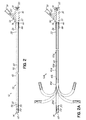
- FIG. 2 shows a cross-section of the mixing tip 14 fluidly connected to the applicator 12.
- the hub 16 further includes a particulate channel 30, a fluid channel 32, and a fluidization chamber 33.
- the particulate channel 30 extends from the particulate port 20 to the fluidization chamber 33.
- the fluid channel 32 extends from the fluid port 18 to the fluidization chamber 33.
- the pressurized gas moves from the fluid port 18, along the fluid channel 32, and into the fluidization chamber 33 for drawing upon the particulate received by the particulate port 20.
- the particulate then moves along the particulate channel 30 and into the fluidization chamber 33.
- the particulate channel 30 also includes a particulate check valve 34 for preventing the particulate from reversing direction back toward the particulate port 20.
- the fluid channel 32 also includes a fluid check valve 35 for similarly preventing the fluid from reversing direction back toward the fluid port 18. Accordingly, the particulate fluidizes with the turbulent gas at the fluidization chamber 33 and, the particulate and gas flow toward the outlet port 26. Due to the relatively high turbulence of the gas within the fluidization chamber 33, the gas and the particulate are generally uniformly mixed in the fluidization chamber 33. That is, the particulate has a relatively uniform density and concentration throughout the gas as the mixture exits the fluidization chamber 33 for the outlet port 26.
- the cannula 15 receives the gas and particulate from the outlet port 26 as the mixture. More particularly, the cannula 15 has a proximal cannula end portion 36 and a distal cannula end portion 38 and includes an outer tube 40 and a hypo tube 42.
- the hypo tube 42 is concentrically supported within the outer tube 40 by proximal and distal plugs 44, 46 respectively positioned at the upstream and distal cannula end portions 36, 38.
- a vent hole 39 also extends through the outer tube 40. Specifically, the vent hole 39 is positioned between the proximal and distal plugs 36, 38 for improving sterilization within the outer tube 40.
- the hypo tube 42 defines a flow channel 48 within the cannula 15.
- the cannula 15 is affixed and sealed within the hub 16 so that the outlet port 26 and the flow channel 48 are in fluid communication for receiving the relatively turbulent flow of fluidized particulate and gas.
- the flow channel 48 extends through the hypo tube 42 from the proximal cannula end portion 36 toward the distal cannula end portion 38, which is configured to connect to the mixing tip 14.
- the mixing tip 14 includes an inlet 50, the outlet 28, and a mixing channel 52 extending therebetween.
- the outer tube 40 extends farther than the hypo tube 42. In this way, the mixing tip 14 is inserted within the outer tube 40 and the hypo tube 42 is inserted into the inlet 50 of the mixing tip 14.
- the flow turbulence may decrease from turbulent to laminar, especially within the stream of gas and particulate immediately adjacent to the hypo tube 42.
- the relatively less turbulent flow and laminar flow of the fluidized particulate causes the particulate to fall from the gas and gather in a rivulet moving toward the distal cannula end portion 38 of the cannula 15.
- the mixing tip 14 is configured for mixing the particulate with the gas and creating turbulent flow in order to re-fluidize the particulate within the gas. In this way, the particulate is generally uniformly distributed throughout the discharging gas with generally uniform density and concentration for application onto the anatomical site.
- FIG. 2A is another embodiment of an applicator 12a for use with the mixing tip 14 in which like numbers indicate like features to that of the previous embodiment.
- the applicator 12a notably includes a cannula 15a having a malleable distal tube 38a, an outer tube 40a, and a hypo tube 42a.
- the hypo tube 42a is positioned within the outer tube 40a and connected at the proximal end portion 36 to the hub 16 as described above.
- the outer tube 40a has a tube end portion 41 a that connects to a malleable end portion 41 b of the malleable distal tube 38a.
- the malleable distal tube 38a and the hypo tube 42a collectively define the flow channel 48.
- the malleable distal tube 38a is connected to the mixing tip 14 such that the mixing channel 52 and the flow channel 48 are in fluid communication.
- the malleable distal tube 38a may be used to position the mixing tip 14 for directing the discharging stream of the fluidized particulate.
- laparoscopic surgery may require the use of a trocar for accessing the anatomical site within the patient. Given the limited space within the patient, accessing the anatomical site may be difficult. However, access to the anatomical site may be improved by bending the malleable distal tube 38a in order to position the outlet 28 of the mixing tip 14 after insertion within the trocar.
- a medical professional such as a doctor or nurse, may insert the mixing tip 14 and a portion of the malleable distal tube 38a into the trocar and bend the malleable distal tube 38a with a forceps to aim at the anatomical site.
- the operator may bend the malleable distal tube 38a into any desirable shape.
- the malleable distal tube 38a maintains the desired shape.
- bending the malleable distal tube 38a to aim the mixing tip 14 may also reduce the necessity of either moving the applicator 12a between various trocars or repositioning the patient to improve the aim of the mixing tip 14 to the anatomical site.
- the mixing tip 14 connected to the malleable distal tube 38a fluidizes the additional fallen particulate for use on the anatomical site. Thereby, the fluidized particulate discharging from the mixing tip 14 may be directed onto an otherwise unreachable or difficult to reach anatomical site with the aid of the malleable distal tube 38a.
- the malleable distal tube 38a is also generally transparent for enhanced visualization of powder passing therethrough. For example, viewing the laparoscopic procedure may be difficult given the inherent challenges of operating within the patient. As such, the medical professional may lack visibility of the mixing tip 14 or portions of the anatomical site during the procedure. However, the medical professional may view the particulate passing through the transparent malleable distal tube 38a in order to ensure that the particulate is being applied to the anatomical site. Finally, with respect to FIGS. 2-4 , the mixing tip 14 for use with both applicators 14, 14a is radiopaque for confirming the position of the mixing tip 14 within the patient via x-rays. Such confirmation may be particularly beneficial when performing the medical procedure with robotic applications.
- the exemplary mixing tip 14 includes a generally cylindrical housing 56 having a proximal end portion 58 and a distal end portion 60.
- the distal end portion 60 includes a front face 62 having the outlet 28, and the proximal end portion 58 includes a rear face 64 having the inlet 50.
- the mixing tip 14 is configured for insertion into the outer tube 40 shown in FIG. 2 .
- the proximal end portion 58 of the housing 56 is sized for insertion into the outer tube 40.
- the inlet 50 is sized for receiving the hypo tube 42 therein.
- the distal end portion 60 includes a lip 66 positioned against the outer tube 40, which is indicative of proper insertion, or installation, within the cannula 15.
- the mixing tip 14 may be similarly connected to and sealed against the cannula 15 using luer locks, fasteners, clips, glue, or any another other structure for sealing and fluidly connecting the mixing channel 52 to the flow channel 48. Furthermore, the mixing tip 14 may be removably connected to the cannula 15 so that various other tips, such as other mixing tips, may be used with the same applicator 12 or even during the same medical procedure.
- FIGS. 3-6 show the mixing tip 14 configured for mixing the fluidized particulate and gas. More particularly, the mixing tip 14 includes an exemplary embodiment of first, second, and third fins 68a, 68b, 68c each projecting inward from the housing 56 and into the mixing channel 52. Furthermore, the first, second, and third fins 68a, 68b, 68c each extend along the mixing channel 52 between the inlet 50 and the outlet 28. According to the exemplary embodiment, the first, second, and third fins 68a, 68b, 68c extend continuously along generally the entire mixing channel 52.
- first, second, and third fins 68a, 68b, 68c may, in the alternative, extend along a portion of the mixing channel 52 between the inlet 50 and outlet 28.
- the one or more of the first, second, and third fins 68a, 68b, 68c may, in the alternative, extend discontinuously along generally the entire mixing channel 52 or extend discontinuously along a portion of the mixing channel 52.
- the fins 68a, 68b, 68c are not intended to be limited to the exemplary embodiment and the extension and/or continuity of the fins 68a, 68b, 68c may vary in accordance with the invention described herein.
- Each of the first, second, and third fins 68a, 68b, 68c are symmetrically positioned along the mixing channel 52 and gradually spiral about the mixing channel 52 in a generally spiral shape for generating turbulence within the fluidized particulate and gas passing therethrough.
- each of the first, second, and third fins 68a, 68b, 68c spiral approximately 120 degrees from the inlet 50 toward the outlet 28.
- the desired spiraling may be used in order to generate more or less turbulence depending on the application and the types of fluid and particulate mixed in accordance with the principles of the invention described herein.
- first, second, and third fins 68a, 68b, 68c define first, second, and third grooves 70a, 70b, 70c that spiral adjacent to each of the fins 68a, 68b, 68c.
- the grooves 70a, 70b, 70c work in coordination with the fins 68a, 68b, 68c for similarly rotating and/or agitating the stream of the fluidized particulate and gas to create additional turbulence.
- each of the first, second, and third fins 68a, 68b, 68c has a triangular profile 72 extending along the mixing channel 52.
- the triangular profile 72 includes a leading face 74 and a trailing face 76 projecting into the mixing channel 52 toward a fin edge 78.
- the leading face 74 is generally convex
- the trailing face 76 is generally concave.
- fins 68a, 68b, 68c may be generally any shape adapted for creating turbulence in the fluidized particulate and gas. Additional turbulence is also created by narrowing the mixing channel 52 from the inlet 50 toward the outlet 28.
- the volume of the mixing channel 52 decreases from the inlet 50 toward the outlet 28, which increases the velocity of the fluidized particulate and gas passing therethrough. In this way, the increased velocity creates additional turbulence for mixing the fluidized particulate and gas.
- the outlet 28 has a diameter of 2 millimeters
- the inlet 50 has a diameter of more than 2 millimeters, e.g., between 2 millimeters and 3 millimeters.
- the inlet 50 and outlet 28 may vary in size for dispensing the particulate and gas, or any particulate or fluid used in a medical procedure.
- FIG. 6 shows a stream of particulate and gas, indicated by first, second, and third arrows 80a, 80b, 80c, entering the inlet 50, moving along the mixing channel 52, and discharging from the outlet 28.
- the fluidized particulate and gas may be stratified into a rivulet of relatively high density particulate flowing into the mixing channel 52 represented by the third arrow 80c.
- the second arrow 80b may be indicative of a relatively low concentration of particulate fluidized within the gas having a relatively turbulent flow.
- the third arrow 80c may be indicative of a relatively laminar flow of relatively low concentration of particulate fluidized within the gas.
- first, second, and third arrows 80a, 80b, 80c As the stream of fluidized particulate and gas represented by first, second, and third arrows 80a, 80b, 80c is forced under pressure into the mixing channel 52, the fins 68a, 68b, 68c and grooves 70a, 70b, 70c spiral the stream in order to generate turbulence within the mixing tip 14. Additional turbulence is created as the mixing channel 52 narrows and the stream of particulate and gas increases in velocity. Finally, the rivulet at the third arrow 80c is guided and lifted along the third groove 70c and directed into the turbulence of the stream.
- the coagulant particulate re-fluidizes into a generally uniform distribution of fluidized coagulant particulate and gas mixture. Accordingly, the practitioner directs and discharges the coagulant particulate with a generally uniform density and concentration onto the anatomical site. At the anatomical site, the coagulant powder promotes the coagulation of the blood for improving the outcome of the medical procedure for the patient.
- the shape and number of fins and grooves may vary to accommodate varying fluids, particulates, or medical procedures.
- the mixing tip 14 may accommodate higher or lower density particulates by increasing or decreasing the size of the mixing channel 52.
- increasing the length and/or number of fins may increase turbulence, while reducing the length and/or number of fins may decrease the likelihood of clogging the mixing channel 52.
- the outlet 28 is generally circular and thus, produces a generally conical plume of fluidized particulate and gas.
- the shape of the outlet 28 may be changed in order to create a generally flat or rectangular plume.
- the flat or rectangular plume may be used for topical surgery, and the conical plume may be used for laparoscopic surgery.
- An applicator and method for dispensing a stream of a particulate and a fluid from a cannula and a mixing tip includes a housing having an inlet, an outlet, and a mixing channel extending therebetween.
- a fin is positioned within the housing and extends along at least a portion of the mixing channel. The fin spirals about the mixing channel from the inlet toward the outlet for mixing and distributing the particulate generally uniformly within the fluid.
- the stream is directed into the mixing channel of the mixing tip and spiraled along the fin within the mixing channel. The spiraling increases turbulence and mixes the stream into a mixed stream of particulate and fluid.
- the mixed stream is discharged from the mixing tip for being dispensed onto an anatomical site.
Landscapes
- Health & Medical Sciences (AREA)
- Engineering & Computer Science (AREA)
- Life Sciences & Earth Sciences (AREA)
- Biomedical Technology (AREA)
- Heart & Thoracic Surgery (AREA)
- Hematology (AREA)
- Anesthesiology (AREA)
- Animal Behavior & Ethology (AREA)
- General Health & Medical Sciences (AREA)
- Public Health (AREA)
- Veterinary Medicine (AREA)
- Dermatology (AREA)
- Medical Informatics (AREA)
- Surgical Instruments (AREA)
- Media Introduction/Drainage Providing Device (AREA)
Applications Claiming Priority (1)
| Application Number | Priority Date | Filing Date | Title |
|---|---|---|---|
| US13/786,901 US9492646B2 (en) | 2013-03-06 | 2013-03-06 | Applicator and method for dispensing a fluid and a particulate |
Publications (2)
| Publication Number | Publication Date |
|---|---|
| EP2774644A1 true EP2774644A1 (de) | 2014-09-10 |
| EP2774644B1 EP2774644B1 (de) | 2019-12-04 |
Family
ID=50193373
Family Applications (1)
| Application Number | Title | Priority Date | Filing Date |
|---|---|---|---|
| EP14158037.3A Active EP2774644B1 (de) | 2013-03-06 | 2014-03-06 | Applikator zur Flüssigkeits- und Partikelabgabe |
Country Status (3)
| Country | Link |
|---|---|
| US (1) | US9492646B2 (de) |
| EP (1) | EP2774644B1 (de) |
| ES (1) | ES2771451T3 (de) |
Cited By (2)
| Publication number | Priority date | Publication date | Assignee | Title |
|---|---|---|---|---|
| CN109046820A (zh) * | 2018-11-02 | 2018-12-21 | 山东大学 | 一种多级同步混粉器及热喷涂装置 |
| EP4313249A4 (de) * | 2021-03-31 | 2024-12-11 | Davol Inc. | Vibrationspulverapplikator |
Families Citing this family (19)
| Publication number | Priority date | Publication date | Assignee | Title |
|---|---|---|---|---|
| CA2889544A1 (en) * | 2012-11-14 | 2014-05-22 | Ams Research Corporation | Cell delivery device and system with anti-clumping feature and methods for pelvic tissue treatment |
| US10441761B2 (en) | 2016-07-01 | 2019-10-15 | Boston Scientific Scimed, Inc. | Delivery devices and methods |
| JP7126506B2 (ja) | 2017-01-10 | 2022-08-26 | ボストン サイエンティフィック サイムド,インコーポレイテッド | 粉末薬剤を送達するための装置および方法 |
| CN111587129A (zh) | 2018-01-12 | 2020-08-25 | 波士顿科学国际有限公司 | 实现止血的粉末 |
| US11766546B2 (en) | 2018-01-31 | 2023-09-26 | Boston Scientific Scimed, Inc. | Apparatuses and methods for delivering powdered agents |
| JP7447100B2 (ja) | 2018-10-02 | 2024-03-11 | ボストン サイエンティフィック サイムド,インコーポレイテッド | 粉末剤を流動化して送達するための装置 |
| EP4579371A3 (de) | 2018-10-02 | 2025-12-24 | Boston Scientific Scimed, Inc. | Vorrichtungen zur fluidisierung und abgabe eines pulverförmigen mittels |
| US12053169B2 (en) | 2019-12-03 | 2024-08-06 | Boston Scientific Scimed, Inc. | Devices and methods for delivering powdered agents |
| US11918780B2 (en) | 2019-12-03 | 2024-03-05 | Boston Scientific Scimed, Inc. | Agent administering medical device |
| EP4309564B1 (de) | 2019-12-03 | 2026-01-28 | Boston Scientific Scimed, Inc. | Medizinische systeme zur wirkstofffreisetzung |
| CN121512581A (zh) | 2019-12-03 | 2026-02-13 | 波士顿科学国际有限公司 | 用于药物输送的医疗装置及相关使用方法 |
| US12370353B2 (en) | 2019-12-20 | 2025-07-29 | Boston Scientific Scimed, Inc. | Agent delivery device |
| US12465698B2 (en) | 2020-01-06 | 2025-11-11 | Boston Scientific Scimed, Inc. | Devices and methods for delivering powdered agents |
| CN114901157B (zh) | 2020-01-06 | 2025-08-12 | 波士顿科学国际有限公司 | 药剂输送系统 |
| EP4106826A1 (de) | 2020-02-18 | 2022-12-28 | Boston Scientific Scimed, Inc. | Hämostatische zusammensetzungen und zugehörige verfahren |
| EP4076213B1 (de) | 2020-03-06 | 2025-08-27 | Boston Scientific Scimed, Inc. | Vorrichtungen zur abgabe von pulverförmigen mitteln |
| AU2021241588B2 (en) | 2020-03-24 | 2026-01-15 | Boston Scientific Scimed, Inc. | Agent delivery systems and methods of using the same |
| EP4135784A1 (de) | 2020-04-17 | 2023-02-22 | Boston Scientific Scimed, Inc. | Hämostatische zusammensetzungen und zugehörige verfahren |
| US12502488B2 (en) | 2020-08-19 | 2025-12-23 | Boston Scientific Scimed, Inc. | Delivery device and methods of use |
Citations (6)
| Publication number | Priority date | Publication date | Assignee | Title |
|---|---|---|---|---|
| US2604094A (en) * | 1949-06-25 | 1952-07-22 | Schenley Ind Inc | Inhaler |
| US4660772A (en) * | 1984-09-26 | 1987-04-28 | A. O. Smith Corporation | Electrostatic powder spray gun nozzle |
| EP0237507A1 (de) * | 1986-03-07 | 1987-09-16 | Aktiebolaget Draco | Vorrichtung zur Inhalation von Pulver |
| DE29516077U1 (de) * | 1995-10-10 | 1997-02-06 | Maslanka, Harald, 78532 Tuttlingen | Sprühvorrichtung |
| US20110178495A1 (en) * | 2010-01-15 | 2011-07-21 | Xin Ji | Internal dry powder delivery system and method thereof |
| WO2012085600A1 (en) * | 2010-12-23 | 2012-06-28 | Profibrix B.V. | Powder delivery device |
Family Cites Families (12)
| Publication number | Priority date | Publication date | Assignee | Title |
|---|---|---|---|---|
| US1784503A (en) * | 1928-09-06 | 1930-12-09 | Cement Gun Construction Co | Cement-gun nozzle |
| US1893210A (en) * | 1931-06-22 | 1933-01-03 | Automatic Sprinkler Co | Fluid distributing device |
| FR2282946A1 (fr) * | 1974-08-30 | 1976-03-26 | Exxon France | Procede et appareil pour pulveriser ou atomiser des liquides et extincteur d'incendie base sur ce procede |
| US4123800A (en) * | 1977-05-18 | 1978-10-31 | Mazzei Angelo L | Mixer-injector |
| US4521349A (en) * | 1983-01-20 | 1985-06-04 | A. R. Wilfley And Sons, Inc. | Fluid diffuser for gases and liquids |
| JP2572001B2 (ja) | 1992-12-28 | 1997-01-16 | 三和産業株式会社 | 吹付機に於ける吹付けノズル体 |
| US5814022A (en) * | 1996-02-06 | 1998-09-29 | Plasmaseal Llc | Method and apparatus for applying tissue sealant |
| US6200288B1 (en) | 1997-08-26 | 2001-03-13 | Queen's University At Kingston | Everting toroid device for insertion into a body cavity |
| DE10240324A1 (de) | 2002-08-31 | 2004-03-11 | Michael Alberti | Duschkopf oder dergleichen |
| WO2005102429A1 (en) * | 2004-04-21 | 2005-11-03 | Innovata Biomed Limited | Inhaler |
| DE102004049983A1 (de) | 2004-10-08 | 2006-04-13 | Hansgrohe Ag | Handbrause |
| CN101346158B (zh) * | 2005-12-23 | 2012-02-22 | 阿斯利康(瑞典)有限公司 | 一种用于粒状药物给药的递送装置及其清洁方法 |
-
2013
- 2013-03-06 US US13/786,901 patent/US9492646B2/en not_active Expired - Fee Related
-
2014
- 2014-03-06 ES ES14158037T patent/ES2771451T3/es active Active
- 2014-03-06 EP EP14158037.3A patent/EP2774644B1/de active Active
Patent Citations (6)
| Publication number | Priority date | Publication date | Assignee | Title |
|---|---|---|---|---|
| US2604094A (en) * | 1949-06-25 | 1952-07-22 | Schenley Ind Inc | Inhaler |
| US4660772A (en) * | 1984-09-26 | 1987-04-28 | A. O. Smith Corporation | Electrostatic powder spray gun nozzle |
| EP0237507A1 (de) * | 1986-03-07 | 1987-09-16 | Aktiebolaget Draco | Vorrichtung zur Inhalation von Pulver |
| DE29516077U1 (de) * | 1995-10-10 | 1997-02-06 | Maslanka, Harald, 78532 Tuttlingen | Sprühvorrichtung |
| US20110178495A1 (en) * | 2010-01-15 | 2011-07-21 | Xin Ji | Internal dry powder delivery system and method thereof |
| WO2012085600A1 (en) * | 2010-12-23 | 2012-06-28 | Profibrix B.V. | Powder delivery device |
Cited By (3)
| Publication number | Priority date | Publication date | Assignee | Title |
|---|---|---|---|---|
| CN109046820A (zh) * | 2018-11-02 | 2018-12-21 | 山东大学 | 一种多级同步混粉器及热喷涂装置 |
| CN109046820B (zh) * | 2018-11-02 | 2019-08-02 | 山东大学 | 一种多级同步混粉器及热喷涂装置 |
| EP4313249A4 (de) * | 2021-03-31 | 2024-12-11 | Davol Inc. | Vibrationspulverapplikator |
Also Published As
| Publication number | Publication date |
|---|---|
| EP2774644B1 (de) | 2019-12-04 |
| ES2771451T3 (es) | 2020-07-06 |
| US20140257174A1 (en) | 2014-09-11 |
| US9492646B2 (en) | 2016-11-15 |
Similar Documents
| Publication | Publication Date | Title |
|---|---|---|
| US9492646B2 (en) | Applicator and method for dispensing a fluid and a particulate | |
| US12502515B2 (en) | Flush enhancing male luer tip design for syringes and any luer connector | |
| JP6654188B2 (ja) | 医療用アプリケータに対する追加物 | |
| CN103889304B (zh) | 至少包含一个腔的多段式套管 | |
| CN106102597A (zh) | 混合喷嘴 | |
| CN105307763A (zh) | 用于改进生物材料水合的装置和方法 | |
| EP4498930B1 (de) | Dichtungsmittelapplikatoren mit misch- und sprühanordnungen mit verformbaren abschnitten | |
| JP2014532476A5 (de) | ||
| CN106535778A (zh) | 腹腔镜喷雾施加器和适配器 | |
| US9603589B2 (en) | Delivery tip for extravascular bioadhesive catheter and methods | |
| US20160051752A1 (en) | Applicator, mixing tip and method for dispensing a mixed fluid | |
| US20250135127A1 (en) | Medical instrument for introducing a fluid therapeutic substance into a cavity of a body | |
| WO2016054355A9 (en) | Suction adapter device | |
| EP4037576B1 (de) | Ausgabesysteme und vorrichtungen mit verstopfungsverhindernden sprühspitzen zur abgabe von zwei oder mehr flüssigkeiten, die miteinander reagieren | |
| CN116600903B (zh) | 生物体用药液注入用具 | |
| EP3125774B1 (de) | Sprühapplikator mit verlängerter spitze für chirurgisches zwei-komponenten-dichtmittel und verfahren zur verwendung davon |
Legal Events
| Date | Code | Title | Description |
|---|---|---|---|
| PUAI | Public reference made under article 153(3) epc to a published international application that has entered the european phase |
Free format text: ORIGINAL CODE: 0009012 |
|
| 17P | Request for examination filed |
Effective date: 20140306 |
|
| AK | Designated contracting states |
Kind code of ref document: A1 Designated state(s): AL AT BE BG CH CY CZ DE DK EE ES FI FR GB GR HR HU IE IS IT LI LT LU LV MC MK MT NL NO PL PT RO RS SE SI SK SM TR |
|
| AX | Request for extension of the european patent |
Extension state: BA ME |
|
| R17P | Request for examination filed (corrected) |
Effective date: 20150310 |
|
| RBV | Designated contracting states (corrected) |
Designated state(s): AL AT BE BG CH CY CZ DE DK EE ES FI FR GB GR HR HU IE IS IT LI LT LU LV MC MK MT NL NO PL PT RO RS SE SI SK SM TR |
|
| STAA | Information on the status of an ep patent application or granted ep patent |
Free format text: STATUS: EXAMINATION IS IN PROGRESS |
|
| 17Q | First examination report despatched |
Effective date: 20170724 |
|
| GRAP | Despatch of communication of intention to grant a patent |
Free format text: ORIGINAL CODE: EPIDOSNIGR1 |
|
| STAA | Information on the status of an ep patent application or granted ep patent |
Free format text: STATUS: GRANT OF PATENT IS INTENDED |
|
| INTG | Intention to grant announced |
Effective date: 20190617 |
|
| RIN1 | Information on inventor provided before grant (corrected) |
Inventor name: HOOGENAKKER, JON E. Inventor name: ROBB, BRADLEY D. Inventor name: LOU, HUADONG |
|
| GRAS | Grant fee paid |
Free format text: ORIGINAL CODE: EPIDOSNIGR3 |
|
| GRAA | (expected) grant |
Free format text: ORIGINAL CODE: 0009210 |
|
| STAA | Information on the status of an ep patent application or granted ep patent |
Free format text: STATUS: THE PATENT HAS BEEN GRANTED |
|
| AK | Designated contracting states |
Kind code of ref document: B1 Designated state(s): AL AT BE BG CH CY CZ DE DK EE ES FI FR GB GR HR HU IE IS IT LI LT LU LV MC MK MT NL NO PL PT RO RS SE SI SK SM TR |
|
| REG | Reference to a national code |
Ref country code: GB Ref legal event code: FG4D |
|
| REG | Reference to a national code |
Ref country code: CH Ref legal event code: EP |
|
| REG | Reference to a national code |
Ref country code: AT Ref legal event code: REF Ref document number: 1208612 Country of ref document: AT Kind code of ref document: T Effective date: 20191215 |
|
| REG | Reference to a national code |
Ref country code: DE Ref legal event code: R096 Ref document number: 602014057695 Country of ref document: DE |
|
| REG | Reference to a national code |
Ref country code: IE Ref legal event code: FG4D |
|
| REG | Reference to a national code |
Ref country code: NL Ref legal event code: MP Effective date: 20191204 |
|
| REG | Reference to a national code |
Ref country code: LT Ref legal event code: MG4D |
|
| PG25 | Lapsed in a contracting state [announced via postgrant information from national office to epo] |
Ref country code: GR Free format text: LAPSE BECAUSE OF FAILURE TO SUBMIT A TRANSLATION OF THE DESCRIPTION OR TO PAY THE FEE WITHIN THE PRESCRIBED TIME-LIMIT Effective date: 20200305 Ref country code: NO Free format text: LAPSE BECAUSE OF FAILURE TO SUBMIT A TRANSLATION OF THE DESCRIPTION OR TO PAY THE FEE WITHIN THE PRESCRIBED TIME-LIMIT Effective date: 20200304 Ref country code: LT Free format text: LAPSE BECAUSE OF FAILURE TO SUBMIT A TRANSLATION OF THE DESCRIPTION OR TO PAY THE FEE WITHIN THE PRESCRIBED TIME-LIMIT Effective date: 20191204 Ref country code: FI Free format text: LAPSE BECAUSE OF FAILURE TO SUBMIT A TRANSLATION OF THE DESCRIPTION OR TO PAY THE FEE WITHIN THE PRESCRIBED TIME-LIMIT Effective date: 20191204 Ref country code: LV Free format text: LAPSE BECAUSE OF FAILURE TO SUBMIT A TRANSLATION OF THE DESCRIPTION OR TO PAY THE FEE WITHIN THE PRESCRIBED TIME-LIMIT Effective date: 20191204 Ref country code: SE Free format text: LAPSE BECAUSE OF FAILURE TO SUBMIT A TRANSLATION OF THE DESCRIPTION OR TO PAY THE FEE WITHIN THE PRESCRIBED TIME-LIMIT Effective date: 20191204 Ref country code: BG Free format text: LAPSE BECAUSE OF FAILURE TO SUBMIT A TRANSLATION OF THE DESCRIPTION OR TO PAY THE FEE WITHIN THE PRESCRIBED TIME-LIMIT Effective date: 20200304 |
|
| PG25 | Lapsed in a contracting state [announced via postgrant information from national office to epo] |
Ref country code: RS Free format text: LAPSE BECAUSE OF FAILURE TO SUBMIT A TRANSLATION OF THE DESCRIPTION OR TO PAY THE FEE WITHIN THE PRESCRIBED TIME-LIMIT Effective date: 20191204 Ref country code: HR Free format text: LAPSE BECAUSE OF FAILURE TO SUBMIT A TRANSLATION OF THE DESCRIPTION OR TO PAY THE FEE WITHIN THE PRESCRIBED TIME-LIMIT Effective date: 20191204 |
|
| PG25 | Lapsed in a contracting state [announced via postgrant information from national office to epo] |
Ref country code: AL Free format text: LAPSE BECAUSE OF FAILURE TO SUBMIT A TRANSLATION OF THE DESCRIPTION OR TO PAY THE FEE WITHIN THE PRESCRIBED TIME-LIMIT Effective date: 20191204 |
|
| REG | Reference to a national code |
Ref country code: ES Ref legal event code: FG2A Ref document number: 2771451 Country of ref document: ES Kind code of ref document: T3 Effective date: 20200706 |
|
| PG25 | Lapsed in a contracting state [announced via postgrant information from national office to epo] |
Ref country code: PT Free format text: LAPSE BECAUSE OF FAILURE TO SUBMIT A TRANSLATION OF THE DESCRIPTION OR TO PAY THE FEE WITHIN THE PRESCRIBED TIME-LIMIT Effective date: 20200429 Ref country code: EE Free format text: LAPSE BECAUSE OF FAILURE TO SUBMIT A TRANSLATION OF THE DESCRIPTION OR TO PAY THE FEE WITHIN THE PRESCRIBED TIME-LIMIT Effective date: 20191204 Ref country code: CZ Free format text: LAPSE BECAUSE OF FAILURE TO SUBMIT A TRANSLATION OF THE DESCRIPTION OR TO PAY THE FEE WITHIN THE PRESCRIBED TIME-LIMIT Effective date: 20191204 Ref country code: NL Free format text: LAPSE BECAUSE OF FAILURE TO SUBMIT A TRANSLATION OF THE DESCRIPTION OR TO PAY THE FEE WITHIN THE PRESCRIBED TIME-LIMIT Effective date: 20191204 Ref country code: RO Free format text: LAPSE BECAUSE OF FAILURE TO SUBMIT A TRANSLATION OF THE DESCRIPTION OR TO PAY THE FEE WITHIN THE PRESCRIBED TIME-LIMIT Effective date: 20191204 |
|
| PG25 | Lapsed in a contracting state [announced via postgrant information from national office to epo] |
Ref country code: IS Free format text: LAPSE BECAUSE OF FAILURE TO SUBMIT A TRANSLATION OF THE DESCRIPTION OR TO PAY THE FEE WITHIN THE PRESCRIBED TIME-LIMIT Effective date: 20200404 Ref country code: SK Free format text: LAPSE BECAUSE OF FAILURE TO SUBMIT A TRANSLATION OF THE DESCRIPTION OR TO PAY THE FEE WITHIN THE PRESCRIBED TIME-LIMIT Effective date: 20191204 Ref country code: SM Free format text: LAPSE BECAUSE OF FAILURE TO SUBMIT A TRANSLATION OF THE DESCRIPTION OR TO PAY THE FEE WITHIN THE PRESCRIBED TIME-LIMIT Effective date: 20191204 |
|
| REG | Reference to a national code |
Ref country code: DE Ref legal event code: R097 Ref document number: 602014057695 Country of ref document: DE |
|
| REG | Reference to a national code |
Ref country code: AT Ref legal event code: MK05 Ref document number: 1208612 Country of ref document: AT Kind code of ref document: T Effective date: 20191204 |
|
| PLBE | No opposition filed within time limit |
Free format text: ORIGINAL CODE: 0009261 |
|
| STAA | Information on the status of an ep patent application or granted ep patent |
Free format text: STATUS: NO OPPOSITION FILED WITHIN TIME LIMIT |
|
| PG25 | Lapsed in a contracting state [announced via postgrant information from national office to epo] |
Ref country code: DK Free format text: LAPSE BECAUSE OF FAILURE TO SUBMIT A TRANSLATION OF THE DESCRIPTION OR TO PAY THE FEE WITHIN THE PRESCRIBED TIME-LIMIT Effective date: 20191204 Ref country code: MC Free format text: LAPSE BECAUSE OF FAILURE TO SUBMIT A TRANSLATION OF THE DESCRIPTION OR TO PAY THE FEE WITHIN THE PRESCRIBED TIME-LIMIT Effective date: 20191204 |
|
| REG | Reference to a national code |
Ref country code: CH Ref legal event code: PL |
|
| 26N | No opposition filed |
Effective date: 20200907 |
|
| PG25 | Lapsed in a contracting state [announced via postgrant information from national office to epo] |
Ref country code: SI Free format text: LAPSE BECAUSE OF FAILURE TO SUBMIT A TRANSLATION OF THE DESCRIPTION OR TO PAY THE FEE WITHIN THE PRESCRIBED TIME-LIMIT Effective date: 20191204 Ref country code: PL Free format text: LAPSE BECAUSE OF FAILURE TO SUBMIT A TRANSLATION OF THE DESCRIPTION OR TO PAY THE FEE WITHIN THE PRESCRIBED TIME-LIMIT Effective date: 20191204 Ref country code: AT Free format text: LAPSE BECAUSE OF FAILURE TO SUBMIT A TRANSLATION OF THE DESCRIPTION OR TO PAY THE FEE WITHIN THE PRESCRIBED TIME-LIMIT Effective date: 20191204 |
|
| REG | Reference to a national code |
Ref country code: BE Ref legal event code: MM Effective date: 20200331 |
|
| PG25 | Lapsed in a contracting state [announced via postgrant information from national office to epo] |
Ref country code: LU Free format text: LAPSE BECAUSE OF NON-PAYMENT OF DUE FEES Effective date: 20200306 |
|
| PG25 | Lapsed in a contracting state [announced via postgrant information from national office to epo] |
Ref country code: IE Free format text: LAPSE BECAUSE OF NON-PAYMENT OF DUE FEES Effective date: 20200306 Ref country code: CH Free format text: LAPSE BECAUSE OF NON-PAYMENT OF DUE FEES Effective date: 20200331 Ref country code: LI Free format text: LAPSE BECAUSE OF NON-PAYMENT OF DUE FEES Effective date: 20200331 |
|
| PG25 | Lapsed in a contracting state [announced via postgrant information from national office to epo] |
Ref country code: BE Free format text: LAPSE BECAUSE OF NON-PAYMENT OF DUE FEES Effective date: 20200331 |
|
| PGFP | Annual fee paid to national office [announced via postgrant information from national office to epo] |
Ref country code: IT Payment date: 20210329 Year of fee payment: 8 Ref country code: FR Payment date: 20210323 Year of fee payment: 8 |
|
| PGFP | Annual fee paid to national office [announced via postgrant information from national office to epo] |
Ref country code: DE Payment date: 20210319 Year of fee payment: 8 Ref country code: GB Payment date: 20210324 Year of fee payment: 8 |
|
| PGFP | Annual fee paid to national office [announced via postgrant information from national office to epo] |
Ref country code: ES Payment date: 20210525 Year of fee payment: 8 |
|
| PG25 | Lapsed in a contracting state [announced via postgrant information from national office to epo] |
Ref country code: TR Free format text: LAPSE BECAUSE OF FAILURE TO SUBMIT A TRANSLATION OF THE DESCRIPTION OR TO PAY THE FEE WITHIN THE PRESCRIBED TIME-LIMIT Effective date: 20191204 Ref country code: MT Free format text: LAPSE BECAUSE OF FAILURE TO SUBMIT A TRANSLATION OF THE DESCRIPTION OR TO PAY THE FEE WITHIN THE PRESCRIBED TIME-LIMIT Effective date: 20191204 Ref country code: CY Free format text: LAPSE BECAUSE OF FAILURE TO SUBMIT A TRANSLATION OF THE DESCRIPTION OR TO PAY THE FEE WITHIN THE PRESCRIBED TIME-LIMIT Effective date: 20191204 |
|
| PG25 | Lapsed in a contracting state [announced via postgrant information from national office to epo] |
Ref country code: MK Free format text: LAPSE BECAUSE OF FAILURE TO SUBMIT A TRANSLATION OF THE DESCRIPTION OR TO PAY THE FEE WITHIN THE PRESCRIBED TIME-LIMIT Effective date: 20191204 |
|
| REG | Reference to a national code |
Ref country code: DE Ref legal event code: R119 Ref document number: 602014057695 Country of ref document: DE |
|
| GBPC | Gb: european patent ceased through non-payment of renewal fee |
Effective date: 20220306 |
|
| PG25 | Lapsed in a contracting state [announced via postgrant information from national office to epo] |
Ref country code: GB Free format text: LAPSE BECAUSE OF NON-PAYMENT OF DUE FEES Effective date: 20220306 Ref country code: FR Free format text: LAPSE BECAUSE OF NON-PAYMENT OF DUE FEES Effective date: 20220331 Ref country code: DE Free format text: LAPSE BECAUSE OF NON-PAYMENT OF DUE FEES Effective date: 20221001 |
|
| REG | Reference to a national code |
Ref country code: ES Ref legal event code: FD2A Effective date: 20230526 |
|
| PG25 | Lapsed in a contracting state [announced via postgrant information from national office to epo] |
Ref country code: IT Free format text: LAPSE BECAUSE OF NON-PAYMENT OF DUE FEES Effective date: 20220306 |
|
| PG25 | Lapsed in a contracting state [announced via postgrant information from national office to epo] |
Ref country code: ES Free format text: LAPSE BECAUSE OF NON-PAYMENT OF DUE FEES Effective date: 20220307 |