EP2774677A2 - Dispositif de réalisation de processus chimiques et/ou biochimiques - Google Patents
Dispositif de réalisation de processus chimiques et/ou biochimiques Download PDFInfo
- Publication number
- EP2774677A2 EP2774677A2 EP14154953.5A EP14154953A EP2774677A2 EP 2774677 A2 EP2774677 A2 EP 2774677A2 EP 14154953 A EP14154953 A EP 14154953A EP 2774677 A2 EP2774677 A2 EP 2774677A2
- Authority
- EP
- European Patent Office
- Prior art keywords
- membrane
- beads
- cavity
- centrifugal force
- force
- Prior art date
- Legal status (The legal status is an assumption and is not a legal conclusion. Google has not performed a legal analysis and makes no representation as to the accuracy of the status listed.)
- Withdrawn
Links
Images

Classifications
-
- B—PERFORMING OPERATIONS; TRANSPORTING
- B01—PHYSICAL OR CHEMICAL PROCESSES OR APPARATUS IN GENERAL
- B01L—CHEMICAL OR PHYSICAL LABORATORY APPARATUS FOR GENERAL USE
- B01L3/00—Containers or dishes for laboratory use, e.g. laboratory glassware; Droppers
- B01L3/50—Containers for the purpose of retaining a material to be analysed, e.g. test tubes
- B01L3/502—Containers for the purpose of retaining a material to be analysed, e.g. test tubes with fluid transport, e.g. in multi-compartment structures
- B01L3/5021—Test tubes specially adapted for centrifugation purposes
- B01L3/50215—Test tubes specially adapted for centrifugation purposes using a float to separate phases
-
- C—CHEMISTRY; METALLURGY
- C07—ORGANIC CHEMISTRY
- C07K—PEPTIDES
- C07K1/00—General methods for the preparation of peptides, i.e. processes for the organic chemical preparation of peptides or proteins of any length
- C07K1/14—Extraction; Separation; Purification
- C07K1/16—Extraction; Separation; Purification by chromatography
- C07K1/22—Affinity chromatography or related techniques based upon selective absorption processes
-
- B—PERFORMING OPERATIONS; TRANSPORTING
- B01—PHYSICAL OR CHEMICAL PROCESSES OR APPARATUS IN GENERAL
- B01L—CHEMICAL OR PHYSICAL LABORATORY APPARATUS FOR GENERAL USE
- B01L3/00—Containers or dishes for laboratory use, e.g. laboratory glassware; Droppers
- B01L3/50—Containers for the purpose of retaining a material to be analysed, e.g. test tubes
- B01L3/508—Rigid containers without fluid transport within
- B01L3/5082—Test tubes per se
-
- B—PERFORMING OPERATIONS; TRANSPORTING
- B01—PHYSICAL OR CHEMICAL PROCESSES OR APPARATUS IN GENERAL
- B01L—CHEMICAL OR PHYSICAL LABORATORY APPARATUS FOR GENERAL USE
- B01L2200/00—Solutions for specific problems relating to chemical or physical laboratory apparatus
- B01L2200/06—Fluid handling related problems
- B01L2200/0647—Handling flowable solids, e.g. microscopic beads, cells, particles
-
- B—PERFORMING OPERATIONS; TRANSPORTING
- B01—PHYSICAL OR CHEMICAL PROCESSES OR APPARATUS IN GENERAL
- B01L—CHEMICAL OR PHYSICAL LABORATORY APPARATUS FOR GENERAL USE
- B01L2200/00—Solutions for specific problems relating to chemical or physical laboratory apparatus
- B01L2200/16—Reagents, handling or storing thereof
-
- B—PERFORMING OPERATIONS; TRANSPORTING
- B01—PHYSICAL OR CHEMICAL PROCESSES OR APPARATUS IN GENERAL
- B01L—CHEMICAL OR PHYSICAL LABORATORY APPARATUS FOR GENERAL USE
- B01L2300/00—Additional constructional details
- B01L2300/04—Closures and closing means
- B01L2300/041—Connecting closures to device or container
- B01L2300/044—Connecting closures to device or container pierceable, e.g. films, membranes
-
- B—PERFORMING OPERATIONS; TRANSPORTING
- B01—PHYSICAL OR CHEMICAL PROCESSES OR APPARATUS IN GENERAL
- B01L—CHEMICAL OR PHYSICAL LABORATORY APPARATUS FOR GENERAL USE
- B01L2300/00—Additional constructional details
- B01L2300/06—Auxiliary integrated devices, integrated components
- B01L2300/0609—Holders integrated in container to position an object
-
- B—PERFORMING OPERATIONS; TRANSPORTING
- B01—PHYSICAL OR CHEMICAL PROCESSES OR APPARATUS IN GENERAL
- B01L—CHEMICAL OR PHYSICAL LABORATORY APPARATUS FOR GENERAL USE
- B01L2300/00—Additional constructional details
- B01L2300/06—Auxiliary integrated devices, integrated components
- B01L2300/0672—Integrated piercing tool
-
- B—PERFORMING OPERATIONS; TRANSPORTING
- B01—PHYSICAL OR CHEMICAL PROCESSES OR APPARATUS IN GENERAL
- B01L—CHEMICAL OR PHYSICAL LABORATORY APPARATUS FOR GENERAL USE
- B01L2300/00—Additional constructional details
- B01L2300/06—Auxiliary integrated devices, integrated components
- B01L2300/0681—Filter
-
- B—PERFORMING OPERATIONS; TRANSPORTING
- B01—PHYSICAL OR CHEMICAL PROCESSES OR APPARATUS IN GENERAL
- B01L—CHEMICAL OR PHYSICAL LABORATORY APPARATUS FOR GENERAL USE
- B01L2300/00—Additional constructional details
- B01L2300/08—Geometry, shape and general structure
- B01L2300/0832—Geometry, shape and general structure cylindrical, tube shaped
-
- B—PERFORMING OPERATIONS; TRANSPORTING
- B01—PHYSICAL OR CHEMICAL PROCESSES OR APPARATUS IN GENERAL
- B01L—CHEMICAL OR PHYSICAL LABORATORY APPARATUS FOR GENERAL USE
- B01L2300/00—Additional constructional details
- B01L2300/08—Geometry, shape and general structure
- B01L2300/0861—Configuration of multiple channels and/or chambers in a single devices
- B01L2300/087—Multiple sequential chambers
-
- B—PERFORMING OPERATIONS; TRANSPORTING
- B01—PHYSICAL OR CHEMICAL PROCESSES OR APPARATUS IN GENERAL
- B01L—CHEMICAL OR PHYSICAL LABORATORY APPARATUS FOR GENERAL USE
- B01L2400/00—Moving or stopping fluids
- B01L2400/04—Moving fluids with specific forces or mechanical means
- B01L2400/0403—Moving fluids with specific forces or mechanical means specific forces
- B01L2400/0409—Moving fluids with specific forces or mechanical means specific forces centrifugal forces
-
- B—PERFORMING OPERATIONS; TRANSPORTING
- B01—PHYSICAL OR CHEMICAL PROCESSES OR APPARATUS IN GENERAL
- B01L—CHEMICAL OR PHYSICAL LABORATORY APPARATUS FOR GENERAL USE
- B01L2400/00—Moving or stopping fluids
- B01L2400/04—Moving fluids with specific forces or mechanical means
- B01L2400/0403—Moving fluids with specific forces or mechanical means specific forces
- B01L2400/043—Moving fluids with specific forces or mechanical means specific forces magnetic forces
-
- B—PERFORMING OPERATIONS; TRANSPORTING
- B01—PHYSICAL OR CHEMICAL PROCESSES OR APPARATUS IN GENERAL
- B01L—CHEMICAL OR PHYSICAL LABORATORY APPARATUS FOR GENERAL USE
- B01L3/00—Containers or dishes for laboratory use, e.g. laboratory glassware; Droppers
- B01L3/50—Containers for the purpose of retaining a material to be analysed, e.g. test tubes
- B01L3/508—Rigid containers without fluid transport within
- B01L3/5082—Test tubes per se
- B01L3/50825—Closing or opening means, corks, bungs
Definitions
- the present invention relates to a device for carrying out chemical and / or biochemical processes and to a use of a reaction container.
- centrifugation is used for many chemical or biochemical processes. Due to the centrifugal force generated here, a substance separation due a density difference between the various components of a mixture can be performed. Furthermore, the centrifugation allows a transport of liquids from a radially inner process step to a radially outward process stage.
- the German patent application DE 10 2010 003 223 A1 describes a system comprising a device intended for insertion into a centrifugal rotor.
- two or more revolver-like bodies are arranged axially one above the other.
- the revolvers contain one or more cavities, in particular reaction chambers, channels and optionally further structures for carrying out processes.
- An acceleration change of the centrifuge activates an integrated mechanism, which works in the manner of a ballpoint pen mechanism.
- the bodies move radially outwards, the bodies being rotated against each other by means of a tooth system and an integrated restoring means. Individual cavities can thereby be interconnected.
- an orientation-dependent opening of individual cavities or vessels of a body is possible, wherein one side of the vessel is provided, for example, with a pierceable foil. With the help of a thorn on the other body, the film is pierced by the movement of the body against each other. In this way, a controlled fluid management in the device can be achieved. For example, fluid guidance can be realized from storage chambers via intermediary processing chambers to collecting cavities for the liquids processed.
- beads for example, to perform a purification of certain molecules.
- certain interaction partners of a molecule to be purified can be coupled or applied.
- the molecule binds to the interaction partner and is thus coupled to the beads.
- the beads can then be isolated from the remaining solution, for example by sedimentation or due to magnetic properties, so that the purification of the molecule can be carried out very efficiently.
- the international patent application WO 01/85341 A1 describes a microfluidic device in the form of a chip, in which a compartment is provided with beads, which are retained with a filter. This chip can be used for bead-based purification processes.
- the device according to the invention is intended for carrying out, in particular for automated, chemical and / or biochemical processes, for example for purification of proteins and / or of genetic material, in particular of DNA or RNA.
- a specific fluid flow in the device is predetermined, for which purpose a centrifugal force is utilized.
- the device may be provided for insertion into a rotor of a centrifuge.
- the device comprises at least two axially superimposed bodies each having at least one cavity.
- a first body for example, a plurality of cavities may be provided, which are provided for various reagents, solutions or mixtures which are required for the respective process.
- one or more cavities may be provided which serve, for example, as reaction spaces.
- the at least two bodies are rotatable relative to one another as a function of a centrifugal force or a force having the same effect, so that in each case a cavity of one body can be brought into spatial proximity with one cavity of the other body, so that a fluid flow can take place.
- the device can for example also be subjected to compressed air. In this way, a rotation of the body can also be achieved, whereby the advantages of a stationary system can be used, for example, various parameters can be adjusted easier than in a centrifuge.
- a membrane is provided in at least one cavity of a body, whose permeability to liquids depends on the acting centrifugal force or the equivalent force is.
- a valve effect is achieved. That is, the fluid flow through the cavity with the membrane is a function of the applied centrifugal force or the equivalent force. A liquid can therefore be repeatedly retained and released in this cavity.
- the membrane in the device according to the invention enables an incubation of a sample or a liquid with a solid phase to be carried out in this cavity.
- beads may be contained in the cavity, which allow by their specific properties, in particular a bond, for example, a protein to be purified or another molecule.
- German patent application DE 10 2010 003 223 A1 is a device with two axially superposed bodies each having at least one cavity known, wherein the bodies are rotated against each other.
- a position-dependent opening of at least one cavity is provided, wherein in particular by means of a mandrel which is arranged on a body, a film which forms a closure of another cavity, is torn open or pierced, and so liquid is released.
- the solution according to the invention has the advantage that the release of the liquid or the opening of a cavity can be carried out several times or is reversible. Depending on the applied centrifugal force or equivalent force, liquid can be released from a cavity or the liquid remains in the cavity.
- the device according to the invention can be used very variably and adapted and set up for very different protocols to be carried out.
- a multiple sample application and run of different buffers can be performed on a bead matrix, wherein the corresponding beads are in the cavity with the membrane.
- a liquid can be released from the cavity several times, in principle any number of times, by applying corresponding centrifugal forces or equivalent forces and can be transferred along the intended fluidic path, for example into a reaction cavity.
- the device according to the invention also has the advantage that the membrane according to the invention shows the effect of a multi-way valve, so that with appropriate control or design of the device and the Zentrifugationsprotokolls the liquid released for a certain time in a defined space can be retained and then forwarded along the intended fluidic path. It can thus be easily incubated several fluids together. Furthermore, the incubation of the liquid with a solid phase is possible, the solid phase being formed, for example, by beads which allow, in a manner known per se, a very effective purification of a target molecule from a solution. Thus, in particular bead-based purification protocols can be performed using the device according to the invention without additional equipment.
- a big advantage is that it eliminates the need for costly magnetic beads that would require special magnetic separation devices to separate them completely.
- the valve action of the membrane is achieved by the pressure dependence of the membrane permeability.
- the membrane is selected so that the pressure of the liquid column is at low centrifugal forces or equivalent forces below the pressure required for a penetration of the membrane with the respective liquid. At low centrifugal force, the "valve" is therefore closed. As the centrifugal force increases, the pressure increases so that the liquid passes through the membrane. With increased centrifugal force, the "valve” is thus open or permeable.
- the pressure dependence of the permeability can be set up and adjusted depending on the application by using a suitable membrane.
- the membrane may be impermeable to liquids at a gravitational acceleration of ⁇ 100 g, and permeable to liquids at a gravitational acceleration of> 100 g.
- g denotes the gravitational acceleration.
- the pore size of the membrane can be chosen, for example, such that the pore size is 10 ⁇ m or smaller, in particular 5 ⁇ m or smaller, or 1 ⁇ m or smaller.
- the pore diameter of the membrane is advantageously smaller than the diameter of the beads.
- the permeability characteristics of a membrane also depend on the material of the membrane.
- the materials chosen for the membrane may have hydrophilic or hydrophobic properties depending on the application. Suitable examples are silica membranes or polymer membranes.
- membranes of PVDF polyvinylidene fluoride
- the wetting properties of the membrane can play a role, so that when choosing a suitable membrane and the properties of the liquid to be retained or flushed through the membrane, can flow.
- the membrane in the device according to the invention can for example be mounted on a porous carrier structure, for example a glass frit.
- the membrane can be fixed and / or sealed with mechanical aids, for example with a sealing ring.
- an engagement of guide springs of the one body is provided in a row of teeth of the other body.
- the term "spring” is understood according to the invention in the sense of a spring in a tongue and groove connection.
- a return means in particular a spring, is provided which acts counter to the centrifugal force or the equivalent force.
- the bodies are arranged in the device so that they are displaced radially outward within a surrounding enveloping body when centrifugal force is applied. Upon application of compressed air in the upper region of the device, the bodies are displaced downwards within the enveloping body.
- One of the bodies is in this case, for example, locked by fixing means so that it can not twist, but is still movable radially or downwards.
- the other body twists by the engagement of the guide springs in a row of teeth of the locked body in the manner of a ballpoint pen mechanism.
- the different cavities of the individual bodies are guided in a guided manner in spatial proximity to each other, so that the fluid flow accordingly can be switched and the process can be performed in this way.
- the invention further comprises the use of a reaction container with a membrane disposed therein, whose permeability to liquids depends on an acting centrifugal force or an equivalent force, for carrying out chemical and / or biochemical processes, in particular for carrying out an automated purification of proteins and / or of genetic material.
- a reaction container with a membrane disposed therein whose permeability to liquids depends on an acting centrifugal force or an equivalent force, for carrying out chemical and / or biochemical processes, in particular for carrying out an automated purification of proteins and / or of genetic material.
- the use according to the invention is particularly suitable for the use of bead-based purification protocols, wherein the membrane exercises a retention function for the beads. Bead-based purification protocols can be carried out according to the invention with very little equipment expense.
- the reaction container can be used in a very advantageous manner for the most diverse purification protocols of biological or other molecules.
- the reaction container is used as part of the device according to the invention already described.
- Fig. 1 shows a cavity with a membrane as essential to the invention element of a device according to the invention.
- the cavity is designed as a reaction container 10, wherein in the direction of the fluid flow, which is indicated by an arrow, a funnel-shaped taper of the reaction container 10 is provided.
- a membrane 11 is arranged, which fills the cross section of the container at this point.
- a porous support or support structure 12 on which the membrane 11 is stably supported.
- glass frits can be used as a porous support structure 12, for example, glass frits can be used.
- Suitable materials for the membrane 11 are, in particular, materials which have a low absorption compared to the substance to be purified.
- PVDF membranes can be used.
- a sealing ring 13 is provided to prevent unwanted fluid flow.
- a liquid column 14 is shown above the membrane 11.
- the pore diameter of the membrane 11 is expediently smaller than the dimensions of the substances to be retained, that is to say in particular of the beads 15.
- the pore diameter is preferably below 10 ⁇ m.
- a pore diameter of ⁇ 1 ⁇ m, for example 0.45 ⁇ m, is particularly suitable.
- beads for example, silica beads, nickel beads, polymer beads or glass beads can be used.
- certain surface properties of the beads are used. For example, it is possible to use native beads which have an affinity for the particular molecule to be purified on account of their material-immanent binding properties. In other cases additional binding chemistries can be used. For example, certain interaction partners of the target molecules to be isolated can be coupled to the beads so as to achieve binding of the target molecule to the beads.
- the beads 15 are stored directly on the membrane 11 (filter membrane). Depending on the centrifugal force or equivalent force applied, the membrane is impermeable or permeable to liquids. So if so Centrifugal force or equivalent force is applied, the liquid 14 penetrates through the membrane 11 and the already permeable support 12 and is discharged along the fluid guide 16. The beads 15 are retained.
- the direction of the fluid flow which is indicated by the arrow, also corresponds to the direction of the acting centrifugal force or the equivalent force.
- the "membrane valve” according to the invention is suitable for various applications, in particular in connection with automated protein purification and / or DNA or RNA purification. It can be used in particular in centrifugal devices, in particular in a system in which two or more axially superimposed bodies are each provided with a cavity and wherein the fluid flow is realized for an automated execution of a purification protocol by a rotation of the body against each other.
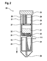
- Fig. 2 shows such a centrifugal system 20 as an example of a device according to the invention.
- three bodies 21, 22 and 23 are provided, which are rotatable against each other.
- the bodies 21, 22 and 23 may also be referred to as revolvers since they each have one or more cavities which may be in different positions relative to one another.
- the revolver 21 and the revolver 23 are hereby locked by appropriate guide means within a surrounding enveloping body 24, so that only the revolver 22 with respect to the revolver 21 and the turret 23 can rotate.
- the enveloping body 24 corresponds to the outer shape of a conventional centrifugation tube, for example, with a volume of 50 ml.
- the enveloping body 24 is closed by a cover 25.
- the revolvers 21 and 22 and possibly also the revolver 23 are arranged such that they are displaceable in the radial direction, indicated by an arrow, as a result of an acting centrifugal force.
- a tearing of cavities 28, 29 or 30 is effected in the revolver 21, depending on the position of the revolver 22 in relation to turret 21.
- the cavities 28 , 29 and 30 are provided in their lower part in this illustration with a pierceable film.
- the liquid contained in the respective cavities 28, 29 and 30 is released in the arrow direction.
- a cell lysate can be stored as a sample in which the molecule to be purified, for example a protein, is located.
- the second turret 22 has a central cavity as the incubation chamber 31.
- the sample so the lysate, and depending on the purification protocol, various reagents are introduced.
- the beads 32 are located in the incubation chamber 31.
- the interaction between the beads 32 as a solid phase and the molecule to be purified takes place from the liquid sample.
- the reaction chamber 31 is limited in a region of a membrane 111.
- the membrane 111 may for example have a diameter of 1 to 7 mm, in particular in adaptation to the dimension of the device according to the invention.
- this membrane 111 is permeable or impermeable to liquids as a function of the acting centrifugal force or equivalent force, so that the membrane 111 can be used as a "valve" to open the incubation chamber 31 for a passage of the liquid.
- the membrane 111 is provided only in a certain delimited area of the bottom of the incubation chamber 31. The remaining area is not passable for liquids.
- the permeable region with the membrane 111 is in spatial proximity or above a certain cavity of the third revolver 23. In this embodiment, two cavities are present in the revolver 23.
- the cavity 33 is intended for waste liquid (waste).
- the cavity 34 is provided for receiving a conventional reaction vessel, for example an Eppendorf reagent vessel, in which an eluate from the incubation chamber 31 can be collected, the eluate containing the purified molecule.
- a replaceability of the reaction vessel in the cavity 34 in this case allows the collection of different fractions from the Purification process that can be suitably analyzed and / or further processed.
- the device 20 according to the invention is suitable, for example, for carrying out a bead-based protein purification.
- the beads 32 are located in the incubation chamber 31 and are supplied with various solutions and reagents from the turret 21.
- the control of the process via a rotation of the turret 22 in relation to the turret 21 and the revolver 23, wherein the spines 27, the reagents and other solutions from the turret 21 in the desired manner in the incubation chamber 31 are released.
- the liquid is transferred from the incubation chamber 31 into the cavities or vessels in the revolver 23. This fluid flow is controlled via the membrane 111, which acts as a valve.
- the control of the "valve" via the applied centrifugal force is that the beads are first washed with an aqueous solution to set the appropriate pH at the bead surface. Subsequently, the cell lysate containing the protein to be purified is added and incubated with the beads, so that specific binding of the proteins to the beads takes place. After incubation, unbound lysate is rinsed out via membrane III with wash buffer before specific elution with an elution buffer. In this way, for example, a His-tag protein, ie a recombinant protein provided with a histidine tag, can be purified from a corresponding bacterial lysate.
- non-magnetic beads with a diameter of, for example,> 5 pm, which are provided with nickel can be used, for example Ni-NTA beads.
- the beads are transferred from one of the pre-storage chambers 28 or 29 into the incubation chamber 31.
- the processing of the purification is analogous to a manual protocol, wherein the required liquids upstream in the cavities of the revolver 21 and released as needed and transferred to the incubation chamber 31.
- the incubation of the fluids may be at rest the centrifuge happen or at low gravitational accelerations, in particular at ⁇ 100 g.
- step action Time centrifugation Loading with the beads Add 100 ⁇ l bead suspension rinse 60 s 1500 g buffers 250 ⁇ l wash buffer 5 s 10 g incubation 55 s 40 g rinse 60 s 1500 g Addition of the lysate 500 ⁇ l lysate 5 s 10 g incubation 55 s / 29 min 40 g / 10 g rinse 60 s 6000 g Washing I 250 ⁇ l wash buffer 5 s 10 g incubation 55 s 40 g rinse 60 s 6000 g Washing II 250 ⁇ l wash buffer 5 s 10 g incubation 55 s 40 g rinse 60 s 6000 g Washing III 250 ⁇ l wash buffer 5 s 10 g incubation 55 s 40 g rinse 60 s 6000 g elution 100 ⁇ l elution buffer 5 s 10 g incubation 55 s / 60 s 40 g / 10 g rinse 60 g Addition of the lysate
- the starting point for the development of a suitable sequence protocol can be a manual protocol, wherein the individual protocol steps are adapted to the beads used and the membrane used.
- the permeability of the membrane may change during the course of the protocol, since the pore system of the membrane is modified by the addition of the lysate can be added by particles and agglomerates from the lysate. This can result in the retention effect of the membrane increasing.
- the device according to the invention is in principle suitable for all types of bead-based purification, for example different proteins, peptides, DNA or RNA from a sample can be purified.
- bead-based purification for example different proteins, peptides, DNA or RNA from a sample can be purified.
- only the selection of respectively suitable beads or a suitable pretreatment of the beads with appropriate interaction partners of the respective substance to be purified and / or an adaptation of the binding agents in a manner known per se is required.
- further diaphragms with valve function can be used in the device in order to effect the fluid flow also between other cavities, for example between reagent holding cavities and an incubation chamber.
Landscapes
- Chemical & Material Sciences (AREA)
- Health & Medical Sciences (AREA)
- Analytical Chemistry (AREA)
- General Health & Medical Sciences (AREA)
- Hematology (AREA)
- Clinical Laboratory Science (AREA)
- Chemical Kinetics & Catalysis (AREA)
- Organic Chemistry (AREA)
- Biochemistry (AREA)
- Biophysics (AREA)
- Genetics & Genomics (AREA)
- Medicinal Chemistry (AREA)
- Molecular Biology (AREA)
- Proteomics, Peptides & Aminoacids (AREA)
- Life Sciences & Earth Sciences (AREA)
- Apparatus Associated With Microorganisms And Enzymes (AREA)
- Physical Or Chemical Processes And Apparatus (AREA)
Applications Claiming Priority (1)
| Application Number | Priority Date | Filing Date | Title |
|---|---|---|---|
| DE102013203682.5A DE102013203682A1 (de) | 2013-03-05 | 2013-03-05 | Vorrichtung zur Durchführung von chemischen und/oder biochemischen Prozessen |
Publications (2)
| Publication Number | Publication Date |
|---|---|
| EP2774677A2 true EP2774677A2 (fr) | 2014-09-10 |
| EP2774677A3 EP2774677A3 (fr) | 2016-04-27 |
Family
ID=50097605
Family Applications (1)
| Application Number | Title | Priority Date | Filing Date |
|---|---|---|---|
| EP14154953.5A Withdrawn EP2774677A3 (fr) | 2013-03-05 | 2014-02-13 | Dispositif de réalisation de processus chimiques et/ou biochimiques |
Country Status (3)
| Country | Link |
|---|---|
| US (1) | US20140256919A1 (fr) |
| EP (1) | EP2774677A3 (fr) |
| DE (1) | DE102013203682A1 (fr) |
Cited By (1)
| Publication number | Priority date | Publication date | Assignee | Title |
|---|---|---|---|---|
| WO2015044037A1 (fr) * | 2013-09-27 | 2015-04-02 | Robert Bosch Gmbh | Dispositif et procédé de préparation et/ou de traitement d'échantillons biologiques |
Families Citing this family (2)
| Publication number | Priority date | Publication date | Assignee | Title |
|---|---|---|---|---|
| DE102015203779A1 (de) * | 2015-03-03 | 2016-09-08 | Robert Bosch Gmbh | Vorrichtung zur automatisierten Prozessierung von Flüssigkeiten |
| EP3496598B1 (fr) * | 2016-08-10 | 2023-12-13 | Mawi DNA Technologies LLC | Dispositif de collecte d'échantillons |
Citations (2)
| Publication number | Priority date | Publication date | Assignee | Title |
|---|---|---|---|---|
| WO2001085341A1 (fr) | 2000-05-12 | 2001-11-15 | Pyrosequencing Ab | Dispositifs microfluidiques |
| DE102010003223A1 (de) | 2010-03-24 | 2011-09-29 | Albert-Ludwigs-Universität Freiburg | Vorrichtung zum Einsetzen in einen Rotor einer Zentrifuge, Zentrifuge und Verfahren zum fluidischen Koppeln von Kavitäten |
Family Cites Families (4)
| Publication number | Priority date | Publication date | Assignee | Title |
|---|---|---|---|---|
| US5061635A (en) * | 1987-07-13 | 1991-10-29 | City Of Hope | Protein or peptide sequencing method |
| US7011755B2 (en) * | 2001-05-31 | 2006-03-14 | Zuk Jr Peter | Disposable vacuum filtration funnel with integral prefilter |
| GB0606822D0 (en) * | 2006-04-05 | 2006-05-17 | Alaska Food Diagnostics | Assay System |
| WO2012031156A1 (fr) * | 2010-09-01 | 2012-03-08 | Life Technologies Corporation | Dispositif de capture et de lyse de micro-organismes dans des liquides et ses procédés d'utilisation |
-
2013
- 2013-03-05 DE DE102013203682.5A patent/DE102013203682A1/de not_active Withdrawn
-
2014
- 2014-02-13 EP EP14154953.5A patent/EP2774677A3/fr not_active Withdrawn
- 2014-03-03 US US14/195,364 patent/US20140256919A1/en not_active Abandoned
Patent Citations (2)
| Publication number | Priority date | Publication date | Assignee | Title |
|---|---|---|---|---|
| WO2001085341A1 (fr) | 2000-05-12 | 2001-11-15 | Pyrosequencing Ab | Dispositifs microfluidiques |
| DE102010003223A1 (de) | 2010-03-24 | 2011-09-29 | Albert-Ludwigs-Universität Freiburg | Vorrichtung zum Einsetzen in einen Rotor einer Zentrifuge, Zentrifuge und Verfahren zum fluidischen Koppeln von Kavitäten |
Cited By (1)
| Publication number | Priority date | Publication date | Assignee | Title |
|---|---|---|---|---|
| WO2015044037A1 (fr) * | 2013-09-27 | 2015-04-02 | Robert Bosch Gmbh | Dispositif et procédé de préparation et/ou de traitement d'échantillons biologiques |
Also Published As
| Publication number | Publication date |
|---|---|
| EP2774677A3 (fr) | 2016-04-27 |
| DE102013203682A1 (de) | 2014-09-11 |
| US20140256919A1 (en) | 2014-09-11 |
Similar Documents
| Publication | Publication Date | Title |
|---|---|---|
| DE102010041621B4 (de) | Verfahren zum Transport magnetischer Partikel | |
| DE102010003223B4 (de) | Vorrichtung zum Einsetzen in einen Rotor einer Zentrifuge, Zentrifuge und Verfahren zum fluidischen Koppeln von Kavitäten | |
| DE69807240T2 (de) | Gussmembranstruktur zur probenaufbereitung | |
| EP1835983B1 (fr) | Procede pour separer des fractions de particules magnetiques par une membrane semipermeable | |
| DE102013203293B4 (de) | Vorrichtung und Verfahren zum Leiten einer Flüssigkeit durch einen ersten oder zweiten Auslasskanal | |
| EP1896858B1 (fr) | Dispositif et procede de preparation d'un echantillon pour une analyse et dispositif et procede d'analyse d'un echantillon | |
| DE10319045A1 (de) | Vorrichtung und Verfahren zur Aufbereitung Biopolymerhaltiger Flüssigkeiten | |
| EP2313755A1 (fr) | Appareillage et procédé de détection automatique de particules biologiques | |
| WO2013072110A1 (fr) | Élément filtrant microfluidique permettant de séparer des constituants d'un échantillon de fluide biologique | |
| EP3230730B1 (fr) | Boîtier de seringue à membranes intégrées pour le pipetage d'une matière biologique | |
| EP2647433B1 (fr) | Pièce d'insertion de flacon de réactif et flacon de réactif | |
| DE102013203682A1 (de) | Vorrichtung zur Durchführung von chemischen und/oder biochemischen Prozessen | |
| EP2129464A1 (fr) | Dispositif de réception, de traitement et de conservation d'échantillons de faible volume | |
| EP4384318B1 (fr) | Isolement d'analytes de différentes classes d'analytes | |
| DE102012213757A1 (de) | Reagenzgefäß-Einsetzteil, Reagenzgefäße, Verfahren zum Zentrifugieren mindestens eines Materials und Verfahren zum Druckbehandeln mindestens eines Materials | |
| DE102015203779A1 (de) | Vorrichtung zur automatisierten Prozessierung von Flüssigkeiten | |
| WO1998016312A1 (fr) | Pipette | |
| WO2014060998A1 (fr) | Composant microfluidique intégré pour l'enrichissement et l'extraction de composants cellulaires biologiques | |
| WO2014019826A1 (fr) | Élément revolver pour un récipient à réactifs, partie de récipient à réactifs et récipient à réactifs pour une centrifugeuse et/ou pour un dispositif à variation de pression | |
| EP3408025B1 (fr) | Tube à structure microfluidique et méthode d'utilisation associée | |
| DE112023005496T5 (de) | Strömungswegvorrichtung, nukleinsäure-reinigungsverfahren undprobenvorbehandlungssystem | |
| EP2834006A1 (fr) | Élément enceinte pour récipient à réactifs et son utilisation | |
| EP2926906A1 (fr) | Dispositif de soupape et dispositif de manipulation de liquides | |
| EP1455943A2 (fr) | Dispositif et procede pour le traitement de substances biologiques ou chimiques ou de melanges de telles substances | |
| WO2015044037A1 (fr) | Dispositif et procédé de préparation et/ou de traitement d'échantillons biologiques |
Legal Events
| Date | Code | Title | Description |
|---|---|---|---|
| PUAI | Public reference made under article 153(3) epc to a published international application that has entered the european phase |
Free format text: ORIGINAL CODE: 0009012 |
|
| 17P | Request for examination filed |
Effective date: 20140213 |
|
| AK | Designated contracting states |
Kind code of ref document: A2 Designated state(s): AL AT BE BG CH CY CZ DE DK EE ES FI FR GB GR HR HU IE IS IT LI LT LU LV MC MK MT NL NO PL PT RO RS SE SI SK SM TR |
|
| AX | Request for extension of the european patent |
Extension state: BA ME |
|
| RIC1 | Information provided on ipc code assigned before grant |
Ipc: C07K 1/22 20060101ALI20151130BHEP Ipc: B01L 3/00 20060101AFI20151130BHEP |
|
| PUAL | Search report despatched |
Free format text: ORIGINAL CODE: 0009013 |
|
| AK | Designated contracting states |
Kind code of ref document: A3 Designated state(s): AL AT BE BG CH CY CZ DE DK EE ES FI FR GB GR HR HU IE IS IT LI LT LU LV MC MK MT NL NO PL PT RO RS SE SI SK SM TR |
|
| AX | Request for extension of the european patent |
Extension state: BA ME |
|
| RIC1 | Information provided on ipc code assigned before grant |
Ipc: C07K 1/22 20060101ALI20160318BHEP Ipc: B01L 3/00 20060101AFI20160318BHEP |
|
| STAA | Information on the status of an ep patent application or granted ep patent |
Free format text: STATUS: THE APPLICATION IS DEEMED TO BE WITHDRAWN |
|
| 18D | Application deemed to be withdrawn |
Effective date: 20160901 |