EP2774735A1 - Station et procédé de traitement pour l'application d'un élément profilé - Google Patents
Station et procédé de traitement pour l'application d'un élément profilé Download PDFInfo
- Publication number
- EP2774735A1 EP2774735A1 EP14156965.7A EP14156965A EP2774735A1 EP 2774735 A1 EP2774735 A1 EP 2774735A1 EP 14156965 A EP14156965 A EP 14156965A EP 2774735 A1 EP2774735 A1 EP 2774735A1
- Authority
- EP
- European Patent Office
- Prior art keywords
- processing station
- profile element
- drive
- element strand
- strand
- Prior art date
- Legal status (The legal status is an assumption and is not a legal conclusion. Google has not performed a legal analysis and makes no representation as to the accuracy of the status listed.)
- Granted
Links
- 238000012545 processing Methods 0.000 title claims abstract description 88
- 238000000034 method Methods 0.000 title claims abstract description 10
- 230000008569 process Effects 0.000 title description 2
- 238000003825 pressing Methods 0.000 claims abstract description 7
- 238000003860 storage Methods 0.000 claims description 33
- 238000000926 separation method Methods 0.000 claims description 9
- 238000001514 detection method Methods 0.000 claims description 4
- 230000004888 barrier function Effects 0.000 claims description 2
- 238000004020 luminiscence type Methods 0.000 claims description 2
- 239000002023 wood Substances 0.000 claims 4
- 239000000463 material Substances 0.000 claims 2
- 238000012986 modification Methods 0.000 description 7
- 230000004048 modification Effects 0.000 description 7
- 230000008859 change Effects 0.000 description 4
- 230000000903 blocking effect Effects 0.000 description 3
- 238000013461 design Methods 0.000 description 3
- 239000003795 chemical substances by application Substances 0.000 description 2
- 230000001276 controlling effect Effects 0.000 description 2
- 238000003780 insertion Methods 0.000 description 2
- 230000037431 insertion Effects 0.000 description 2
- 238000012432 intermediate storage Methods 0.000 description 2
- 230000001360 synchronised effect Effects 0.000 description 2
- 208000027418 Wounds and injury Diseases 0.000 description 1
- 238000013459 approach Methods 0.000 description 1
- 230000003139 buffering effect Effects 0.000 description 1
- 238000004891 communication Methods 0.000 description 1
- 230000006378 damage Effects 0.000 description 1
- 238000011161 development Methods 0.000 description 1
- 230000005484 gravity Effects 0.000 description 1
- 208000014674 injury Diseases 0.000 description 1
- 238000004519 manufacturing process Methods 0.000 description 1
- 230000007246 mechanism Effects 0.000 description 1
- 230000002093 peripheral effect Effects 0.000 description 1
- 230000001105 regulatory effect Effects 0.000 description 1
- 239000000523 sample Substances 0.000 description 1
- 239000012780 transparent material Substances 0.000 description 1
Images


Classifications
-
- B—PERFORMING OPERATIONS; TRANSPORTING
- B27—WORKING OR PRESERVING WOOD OR SIMILAR MATERIAL; NAILING OR STAPLING MACHINES IN GENERAL
- B27M—WORKING OF WOOD NOT PROVIDED FOR IN SUBCLASSES B27B - B27L; MANUFACTURE OF SPECIFIC WOODEN ARTICLES
- B27M3/00—Manufacture or reconditioning of specific semi-finished or finished articles
- B27M3/04—Manufacture or reconditioning of specific semi-finished or finished articles of flooring elements, e.g. parqueting blocks
-
- B—PERFORMING OPERATIONS; TRANSPORTING
- B27—WORKING OR PRESERVING WOOD OR SIMILAR MATERIAL; NAILING OR STAPLING MACHINES IN GENERAL
- B27M—WORKING OF WOOD NOT PROVIDED FOR IN SUBCLASSES B27B - B27L; MANUFACTURE OF SPECIFIC WOODEN ARTICLES
- B27M3/00—Manufacture or reconditioning of specific semi-finished or finished articles
- B27M3/0013—Manufacture or reconditioning of specific semi-finished or finished articles of composite or compound articles
- B27M3/0066—Manufacture or reconditioning of specific semi-finished or finished articles of composite or compound articles characterised by tongue and groove or tap hole connections
-
- E—FIXED CONSTRUCTIONS
- E04—BUILDING
- E04F—FINISHING WORK ON BUILDINGS, e.g. STAIRS, FLOORS
- E04F2201/00—Joining sheets or plates or panels
- E04F2201/05—Separate connectors or inserts, e.g. pegs, pins, keys or strips
-
- F—MECHANICAL ENGINEERING; LIGHTING; HEATING; WEAPONS; BLASTING
- F16—ENGINEERING ELEMENTS AND UNITS; GENERAL MEASURES FOR PRODUCING AND MAINTAINING EFFECTIVE FUNCTIONING OF MACHINES OR INSTALLATIONS; THERMAL INSULATION IN GENERAL
- F16B—DEVICES FOR FASTENING OR SECURING CONSTRUCTIONAL ELEMENTS OR MACHINE PARTS TOGETHER, e.g. NAILS, BOLTS, CIRCLIPS, CLAMPS, CLIPS OR WEDGES; JOINTS OR JOINTING
- F16B5/00—Joining sheets or plates, e.g. panels, to one another or to strips or bars parallel to them
- F16B5/0004—Joining sheets, plates or panels in abutting relationship
- F16B5/0056—Joining sheets, plates or panels in abutting relationship by moving the sheets, plates or panels or the interlocking key perpendicular to the main plane
Definitions
- the present invention relates to a processing station for attaching a profile element, in particular a welt, to a particular plate-shaped workpiece, a processing machine with such a processing station and a method for attaching a profile element to a preferably plate-shaped workpiece.
- the mentioned workpieces are used purely as floorboards, but can be used in other areas of the woodworking industry.
- the DE 2006 011 887 A1 which relates to a locking member for a quadrangular panel-type fastening system, the locking member having an inserting portion for inserting the locking member into a locking groove of a first panel inserted in the longitudinal direction of an edge of the panel in an insertion position and a locking portion for engaging an undercut detent recess is provided, which extend in a laying arrangement of the panels in an opposite edge of a second panel and in the longitudinal direction of this edge.
- the feed device has at least one feed roller with which a rotational movement is transmitted via a frictional contact on the blocking element strand.
- the pressing device has at least one pressure roller, by means of which a pressing force perpendicular to the edge of the panel can be generated, and wherein with the pressure roller whose rotational movement by frictional contact in a transport movement of the locking element is convertible. In particular, this happens from the time when the blocking element has been separated from the blocking element strand.
- the pressure roller is driven so that its peripheral speed is synchronized with the transport speed of the panel in the production line.
- the object of the present invention is to provide a processing station and a method with which profile elements can be attached to a workpiece with precise position and with a short cycle time.
- Such a processing station is provided by the subject-matter of independent claim 1.
- a method is listed in claim 14.
- One of the main ideas of the present invention is to supply a profile element strand of a pressure roller for pressing a profile element against a workpiece torsion as possible. Further, a free-rotating pressure roller is provided, which is not active itself, ie via a motor or a mechanical gear, driven, but rotates together with the supplied profile element strand and possibly the passing workpiece and provides a contact force.
- the temporary storage of the fastening machine according to the invention is vertically aligned, a particularly smooth intermediate storage is provided, are applied in the extremely low tensile forces on the profile element strand.
- the (first or second) feed drive ensures that the profile element strand is pushed from the storage device coming in the vertical direction upwards in the buffer.
- the (first or second) intermediate drive in turn ensures a promotion of the profile element strand in the direction of the pressure roller, wherein the profiled element strand can be separated at least before the final attachment of a profile element by means of a separation station.
- the profiled element strand is fed to the pressure roller, preferably in such a way that the profiled element strand is aligned substantially horizontally in the region of the pressure roller.
- a first guide channel and / or between the intermediate store and the intermediate drive a second guide channel is provided in the direction of passage of the profile element strand between the feed and the buffer. Through the guide channels of the profile element strand is passed torsion.
- the processing station may have a compressed air device, which can set the freely rotating pressure roller in a rotary motion.
- the free-rotating pressure roller can be rotated passively by a compressed air plus is applied to this. This happens in particular when a workpiece approaches the pressure roller or when the operation of the machine is started.
- a detection device is provided, in particular in the region of the temporary storage device, with which a fill level of the intermediate store, in particular a length of the section of the profile element line provided in the temporary store, is monitored.
- the detection device may be one or more light barriers.
- the feed motor can in this way receive information that a further section of the profile element strand is to be fed into the buffer.
- the separation station for separating the profile element strand may comprise a circular blade. This is provided in particular concealed, so that there is no risk of injury to the operator.
- the temporary storage is covered by a transparent cover element. In this way, it is possible for an operator to check the length of the profile element strand recorded in the intermediate memory and, if necessary, to identify errors during the transport of the profile element strand within the intermediate memory.
- the feed has a first and a second feed drive for feeding a profile element strand from a memory and / or the intermediate drive has a first and a second intermediate drive for conveying a profile element strand from the buffer to the pressure roller.
- a luminescence button can be provided, which is set up to monitor the attachment, in particular the correct insertion, of the profile element strand on the workpiece (or a groove provided thereon). In this way, the quality of the processed with the processing station workpieces can be continuously ensured.
- a deflection device may be attached, wherein the profile element strand preferably leaves the storage device in a substantially horizontal direction and is deflected by the deflection device in a substantially vertical direction, wherein the deflection device comprises in particular a feed tube or a deflection roller.
- the feed tube this particular is provided at the entrance of a die.
- an outlet device may be provided at the outlet of the feed tube, which may cause, for example, a rotation of the profile element strand.
- the feed drive (or the feed drives) and / or the intermediate drive (or the intermediate drives) described above preferably have a profiled transport roller and also a profiled counterpressure roller, with which the profiled element strand can be safely received and conveyed.
- the present invention is further directed to a processing machine having a processing station as described above, which processing machine comprises a conveyor for moving workpieces along the processing station.
- the processing station according to the invention can be particularly easy in such Processing machine to be integrated.
- such a processing machine may further comprise a preferably movable storage device in the form of a storage roll on which a reel with a rolled profile element strand can be accommodated.
- the storage device may have its own drive to supply the profile element strand to the processing station.
- the storage device can also have a dancer roller for regulating the drive.
- the profile element strand is guided over the dancer roller, and depending on the position of the dancer roller, the drive of the storage device is started.
- a preferably mechanical probe can be provided which monitors whether the workpiece guided into the region of the processing station is actually prepared for the attachment of a profile element strand. In particular, it is monitored whether a groove is introduced into the workpiece. If this is not the case, the attachment of the profile element strand can be prevented based on information from the button described. There is thus no machine downtime.
- a processing machine with a processing station is part of the invention, which processing machine has a conveyor for moving workpieces along the processing station. This movement of the workpieces should preferably take place in a horizontal direction, so that the workpieces can pass the processing station and be provided with a profile element in their region.
- the processing machine further comprises a preferably movable storage device in the form of a storage role, in particular with a preferably centrally arranged drive and for example a Buffer device, in particular a dancer roller, is provided for controlling the drive.
- a Buffer device in particular a dancer roller
- a deflection device is provided, wherein the profile element strand preferably leaves the storage device in a substantially horizontal direction and is deflected by the deflection in a substantially vertical direction.
- the memory device mentioned above in connection with the processing machine can also be considered individually.
- a preferably movable storage device is provided in the form of a storage roller, which is provided in particular with a preferably centrally arranged drive and, for example, a dancer roller for controlling the drive.
- the method according to the invention can be used, in particular, with the processing station or the processing machine having it, having one of the abovementioned embodiments.
- Fig. 1 shows a perspective view of a processing machine 1, at which a processing station 10th according to a preferred embodiment of the present invention is mounted.
- a processing station 10th according to a preferred embodiment of the present invention is mounted.
- plate-shaped workpieces or panels can be conveyed in a horizontal direction, so that the workpieces are guided past the processing station 10 (in Fig. 1 eg from right to left).
- processing station 10 By processing station 10, as explained in detail below, a profile element, also called Keder, introduced into a groove of the respective workpiece.
- the profile element strand itself is not explicitly shown in the figures, however, its direction is indicated by the reference numeral K, so that with reference to the direction of the profile element strand below only the profile element strand K is mentioned.
- the processing station 10 has a carrier element 10a, which is vertically aligned in the installed state of the processing station 10 in the processing machine 1, and a cover element 10b.
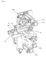
- the cover element 10b was in the in Fig. 2 omitted view, so that a concealed by the cover 10 b portion of the processing station 10 is exposed.
- the covering element 10b may be made of a transparent material, so that an operator can recognize the filling level of the Keder strand K within the processing station 10.
- the processing station 10 comprises a first feed drive 20a and a second feed drive 20b, which are each designed as a servomotor in the present embodiment.
- a Kederstrang K other conveyor mechanisms for moving the profile element strand K (hereinafter referred to as Kederstrang K) are conceivable.
- the feed drives 20a, 20b With each of the feed drives 20a, 20b, a Keder strand K can be supplied from a storage device 300 described later in the processing station 10.
- the feed drives 20a, 20b each have transport rollers (not shown), which are profiled in such a way that they can grasp the Keder strand K and remove it from the storage device.
- Kederstrfite K Since two feed drives 20a, 20b are provided, it is possible to feed one Keder strand K with one of the feed drives, while at the other feed drive a change of the Keder strand K is made. Thus, substantially without interrupting the operation of the processing station 10 Kederstrfite K can be changed.
- a first feed channel 11a associated with the first feed drive 20a and a second feed channel assigned to the second feed drive 20b but not shown in detail are provided in the lower section of the processing station 10.
- a Keder strand K is supplied to the respective feed drive, which forwards this Keder strand K into a first feed drive 20a associated first guide channel 12a and another the second feed drive 20b associated guide channel.
- the first guide channel 12a provides in the running direction of the Kederstrangs K a connection between the first feed drive 20a and a latch 13a, wherein the latch 13a between the support member 10a and the cover 10b is formed.
- the Kederstrang K is relatively free to move, and is characterized by the upper in the vertical direction Rounding 13A of the latch 13a deflected from a more vertical direction in a vertically downward direction, so that the Kederstrang K enters a second guide channel 14a.
- the deflection of the Kederstrangs K in the latch 13a is due to gravity or by said upper rounding 13A of the latch 13a.
- the Keder strand K engages with a first intermediate drive 30a.
- the first intermediate drive 30a thus pulls the keder strand K out of the intermediate storage 13a and guides the keder strand in the direction of a pressure roller 50.
- a second feed drive 20b is further provided, which can lead another Keder strand into a further buffer (not shown). Furthermore, a second feed drive 30b is shown, which leads this other Kederstrang K to the separation station 40 explained below. Due to the double design of the feed drives, latches and intermediate drives, a keder change in the region of the separation station 40 can be provided.
- the separation station 40 In the direction of passage of the Kederstrangs K subsequent to the first and second intermediate drive 30a, 30b mounted on the support member 10a of the processing station 10 separation station 40 is provided, with which the Kederstrang K can be divided into Kederiata.
- the separation station 40 includes a housing 41 which receives a circular blade.
- they are also other release agents conceivable, for example, saw, linear blade, scissors or similar release agents.
- the separation of the Kederstrangs K takes place in coordination with the dimension of the workpiece, so for example, an introduced into the workpiece piece groove for receiving a portion of the Kederstrangs K.
- the processing station 10 further comprises, on a plate 16 connected to the carrier element 10a, a freely rotating pressure roller 50 whose axis of rotation 51 extends in a substantially vertical direction, while the Keder strand K in this region of the processing station 10 feeds the pressure roller 50 in a substantially horizontal direction become.
- the supply of a Kederstrangs K is ensured by the first and second intermediate drive 30a, 30b, while the free-rotating pressure roller 50 provides a pressing force to press a portion of the Kederstrangs K against a past the pressure roller 50 workpiece.
- one or more Nachdrückrollen be provided.
- the freely rotating pressure roller 50 does not have its own drive. Further, no gear is provided to transmit a rotational movement to the pressure roller 50.
- the pressure roller 50 can be rotated passively, for example, by the pressure roller 50 is brought into contact with the Kederstrang K and the passing workpiece.
- a compressed air device is provided, which sets the pressure roller 50 by a compressed air pulse in a rotational movement. This happens in particular when a workpiece on the pressure roller 50 tapers, in which a portion of the Kederstrangs K is to be introduced.
- the pressure roller 50 is given an initial rotation according to this modification, so that the pressure roller 50 does not begin to turn on contact with the workpiece. Although in this way no complete synchronization of the rotation of the pressure roller 50 takes place with the passing workpiece. However, such a complete synchronization of the movement speeds is not necessary with a free-rotating pressure roller.
- both a first and a second feed drive 20a, 20b and a first and a second intermediate drive 30a, 30b are provided.
- a feed drive or an intermediate drive can be provided.
- the second feed drive and the second intermediate drive are not shown, even if their attachment to the carrier element 10a is already prepared.
- the processing station 10 can also ensure more than two Kederstrfite K to the separation station 40 and the pressure roller 50 with appropriate design.
- the processing station 10 can also ensure more than two Kederstrfite K to the separation station 40 and the pressure roller 50 with appropriate design.
- i.a. further Zunaturalantriebe or intermediate drives provided.
- storage device 300 is provided with rollers 301 so that it can be moved in the area of the processing machine 1. According to an alternative embodiment, however, the storage device 300 can also be set up immovably in the region of the processing machine 1.
- the memory device 300 may have a residual length detection device with which the length of the Keder strand K present in the memory device 300 is monitored.
- the memory device 300 has a first wall 302 and a second wall 303. Furthermore, the memory device 300 comprises a rotation axis 304 and a ring 305 which can be rotated by means of the rotation axis 304.
- the ring 305 accommodates conical mandrels 306 (in the present embodiment, a plurality of mandrels 306, for example, 5 or 6) on which a reel can be received.
- conical mandrels 306 in the present embodiment, a plurality of mandrels 306, for example, 5 or 6) on which a reel can be received.
- the ring 305 rotatable about the axis of rotation 304 is attached to the first wall 302.
- a rotatable ring for receiving a reel can be arranged. If two reels are provided on the memory device 300, two welt strands can thus be supplied to the processing station 10 by a memory device.
- a deflection device 200 is provided in the vertical direction below the processing station 10, which in the illustrated embodiment comprises a first deflection roller 201 and a second deflection roller 202.
- the axes of rotation of the first and second deflection rollers 201, 202 extend in a substantially horizontal direction.
- the illustrated pulleys 201, 202 are rotatably mounted in the deflecting device 200 independently of one another via a common axis, it can be seen that the pulleys 201, 202 can also be provided separately from one another.
- the deflection device can also be attached to the processing station 10 according to a further modification.
- the first deflection roller 201 is in this case arranged such that a Keder strand K coming from the storage device 300 can reach the region of the first supply drive 20a, whereas a Keder strand K supplied via the second deflection roller 202 into the region of the second supply drive 20b by a storage device (not shown) can get.
- a feed tube 200a (see FIG. 5 )
- the holder 201a may be attached to the processing station 10 or to the processing machine 1.
- a die 202a is provided, via which the Kederstrang K enters the feed tube 200a.
- the die 202a ensures that the keder strand K can only be inserted into the feed tube 200a in a certain orientation.
- an output device 203a is provided, in which the Kederstrang K is rotated. This rotation can be calculated from a comparison of the profile on the die 202a in comparison to the profile on the output device 203a in FIG Fig. 5 remove.
- the guidance and alignment of the Kederstrangs K can be made even more flexible. Also, the Kederstrang can quite easily be inserted into the die 202a, wherein the profile of the die 200a predetermines the orientation of the Keder strand. This design is also extremely compact.
- a memory device 300a In Fig. 6 an alternative embodiment of a memory device 300a is shown. This has a arranged in the region of the axis of rotation 304 drive motor 350, with which the Kederstrang K receiving reel is rotated. Furthermore, the storage device 300a comprises a buffer device 360, in particular a dancer roller, over which the Kederstrang K is guided, and which controls the operation of the drive motor 350.
- the processing station 10 and possibly the memory device with the buffer means a buffering of the supplied Kederstrangs K is achieved.
- the Kederstrang be promoted substantially constant from the storage device to the processing station, while the application of portions of the Kederstrangs K to passing workpieces occurs in batches.
Landscapes
- Engineering & Computer Science (AREA)
- Life Sciences & Earth Sciences (AREA)
- Manufacturing & Machinery (AREA)
- Wood Science & Technology (AREA)
- Forests & Forestry (AREA)
- Attitude Control For Articles On Conveyors (AREA)
- Processing And Handling Of Plastics And Other Materials For Molding In General (AREA)
Applications Claiming Priority (1)
| Application Number | Priority Date | Filing Date | Title |
|---|---|---|---|
| DE102013204028.8A DE102013204028A1 (de) | 2013-03-08 | 2013-03-08 | Verarbeitungsstation zum Anbringen eines Profilelements |
Publications (2)
| Publication Number | Publication Date |
|---|---|
| EP2774735A1 true EP2774735A1 (fr) | 2014-09-10 |
| EP2774735B1 EP2774735B1 (fr) | 2019-10-30 |
Family
ID=50193267
Family Applications (1)
| Application Number | Title | Priority Date | Filing Date |
|---|---|---|---|
| EP14156965.7A Active EP2774735B1 (fr) | 2013-03-08 | 2014-02-27 | Station et procédé de traitement pour l'application d'un élément profilé |
Country Status (2)
| Country | Link |
|---|---|
| EP (1) | EP2774735B1 (fr) |
| DE (1) | DE102013204028A1 (fr) |
Cited By (8)
| Publication number | Priority date | Publication date | Assignee | Title |
|---|---|---|---|---|
| CN109312567A (zh) * | 2016-06-29 | 2019-02-05 | 瓦林格创新股份有限公司 | 用于插入榫舌的方法和装置 |
| EP3492231A1 (fr) * | 2017-11-30 | 2019-06-05 | IMA Klessmann GmbH | Dispositif de traitement des bords |
| EP3478468A4 (fr) * | 2016-06-30 | 2020-03-04 | Välinge Innovation AB | Dispositif d'insertion d'une languette |
| EP2986429B1 (fr) * | 2013-04-19 | 2020-12-09 | Düspohl Maschinenbau GmbH | Dispositif et procede pour couvrir des bords de panneaux |
| US10933592B2 (en) | 2016-06-29 | 2021-03-02 | Valinge Innovation Ab | Method and device for inserting a tongue |
| US10953566B2 (en) | 2016-12-22 | 2021-03-23 | Valinge Innovation Ab | Device for inserting a tongue |
| US11331824B2 (en) | 2016-06-29 | 2022-05-17 | Valinge Innovation Ab | Method and device for inserting a tongue |
| US11480204B2 (en) | 2019-04-05 | 2022-10-25 | Valinge Innovation Ab | Automated assembly |
Citations (4)
| Publication number | Priority date | Publication date | Assignee | Title |
|---|---|---|---|---|
| US1977080A (en) * | 1931-09-08 | 1934-10-16 | Midland Creosting Company | Apparatus for making flooring |
| WO1997005993A1 (fr) * | 1995-08-04 | 1997-02-20 | Bortolini Engineering S.N.C. | Machine a border et a dresser des panneaux |
| DE102006011887A1 (de) | 2006-01-13 | 2007-07-19 | Akzenta Paneele + Profile Gmbh | Sperrelement, Paneel mit separatem Sperrelement, Verfahren zur Installation eines Paneelbelags aus Paneelen mit Sperrelementen sowie Verfahren und Vorrichtung zur Vormontage eines Sperrelements an einem Paneel |
| EP2052822A1 (fr) * | 2007-10-22 | 2009-04-29 | SCM GROUP S.p.A. | Procédé et appareil d'emboîture |
Family Cites Families (10)
| Publication number | Priority date | Publication date | Assignee | Title |
|---|---|---|---|---|
| US3854512A (en) * | 1973-06-11 | 1974-12-17 | Roberts Consolidated Ind | Method of cutting flat sheets into strips |
| DE2851582A1 (de) * | 1978-11-29 | 1980-06-12 | Gerbl Karl Heinz | Profilbrett fuer wand-, deckenverkleidungen o.dgl. und verfahren zur herstellung des profilbrettes |
| DE4135727A1 (de) * | 1991-05-03 | 1992-11-05 | Rueckle Carl Maschinenbau | Verfahren und vorrichtung zum zusammensetzen und verleimen von einzelnen holzelementen |
| US6058991A (en) * | 1999-03-22 | 2000-05-09 | Hill; David A. | Method for making a wood product |
| DE19917741A1 (de) * | 1999-04-20 | 2000-10-26 | Ima Maschinenfabriken Klessmann Gmbh | Vorrichtung zum Anfahren eines Kantenstreifens an eine Schmalflächenseite einer eckigen Platte |
| DE10038005C2 (de) * | 2000-08-04 | 2002-11-07 | Reich Spezialmaschinen Gmbh | Vorrichtung zum Zuführen einer Anleimkante |
| DE10064280C1 (de) * | 2000-12-22 | 2002-10-10 | Huelsta Werke Huels Kg | Platte für den Innenausbau sowie Verfahren zum Erstellen von neuen Wänden eines Raumes oder zur Verkleidung von vorhandenen Flächen eines Raumes |
| DE102004015604B4 (de) * | 2004-03-30 | 2006-03-02 | Kronotec Ag | Vorrichtung zum Einbringen eines Streifens in eine Nut |
| DE102004062648B4 (de) * | 2004-12-21 | 2006-09-07 | Kronotec Ag | Vorrichtung zum Einsetzen von Federn in die Stirn- und/oder Längsseiten technischer Holzprodukte |
| EP2353821B1 (fr) * | 2010-01-14 | 2012-04-04 | Falquon GmbH | Procédé et dispositif de raccordement d'une bordure avec un bord latéral d'un panneau |
-
2013
- 2013-03-08 DE DE102013204028.8A patent/DE102013204028A1/de not_active Withdrawn
-
2014
- 2014-02-27 EP EP14156965.7A patent/EP2774735B1/fr active Active
Patent Citations (4)
| Publication number | Priority date | Publication date | Assignee | Title |
|---|---|---|---|---|
| US1977080A (en) * | 1931-09-08 | 1934-10-16 | Midland Creosting Company | Apparatus for making flooring |
| WO1997005993A1 (fr) * | 1995-08-04 | 1997-02-20 | Bortolini Engineering S.N.C. | Machine a border et a dresser des panneaux |
| DE102006011887A1 (de) | 2006-01-13 | 2007-07-19 | Akzenta Paneele + Profile Gmbh | Sperrelement, Paneel mit separatem Sperrelement, Verfahren zur Installation eines Paneelbelags aus Paneelen mit Sperrelementen sowie Verfahren und Vorrichtung zur Vormontage eines Sperrelements an einem Paneel |
| EP2052822A1 (fr) * | 2007-10-22 | 2009-04-29 | SCM GROUP S.p.A. | Procédé et appareil d'emboîture |
Cited By (13)
| Publication number | Priority date | Publication date | Assignee | Title |
|---|---|---|---|---|
| EP2986429B1 (fr) * | 2013-04-19 | 2020-12-09 | Düspohl Maschinenbau GmbH | Dispositif et procede pour couvrir des bords de panneaux |
| CN109312567B (zh) * | 2016-06-29 | 2021-06-01 | 瓦林格创新股份有限公司 | 用于插入榫舌的方法和装置 |
| US11358301B2 (en) | 2016-06-29 | 2022-06-14 | Valinge Innovation Ab | Machine for inserting a tongue |
| EP3478901A4 (fr) * | 2016-06-29 | 2020-01-22 | Välinge Innovation AB | Procédé et dispositif d'insertion d'une languette |
| CN109312567A (zh) * | 2016-06-29 | 2019-02-05 | 瓦林格创新股份有限公司 | 用于插入榫舌的方法和装置 |
| US10828798B2 (en) | 2016-06-29 | 2020-11-10 | Valinge Innovation Ab | Method and device for inserting a tongue |
| US10933592B2 (en) | 2016-06-29 | 2021-03-02 | Valinge Innovation Ab | Method and device for inserting a tongue |
| US11331824B2 (en) | 2016-06-29 | 2022-05-17 | Valinge Innovation Ab | Method and device for inserting a tongue |
| EP3478468A4 (fr) * | 2016-06-30 | 2020-03-04 | Välinge Innovation AB | Dispositif d'insertion d'une languette |
| US11045933B2 (en) | 2016-06-30 | 2021-06-29 | Valinge Innovation Ab | Device for inserting a tongue |
| US10953566B2 (en) | 2016-12-22 | 2021-03-23 | Valinge Innovation Ab | Device for inserting a tongue |
| EP3492231A1 (fr) * | 2017-11-30 | 2019-06-05 | IMA Klessmann GmbH | Dispositif de traitement des bords |
| US11480204B2 (en) | 2019-04-05 | 2022-10-25 | Valinge Innovation Ab | Automated assembly |
Also Published As
| Publication number | Publication date |
|---|---|
| DE102013204028A1 (de) | 2014-09-11 |
| EP2774735B1 (fr) | 2019-10-30 |
Similar Documents
| Publication | Publication Date | Title |
|---|---|---|
| EP2774735B1 (fr) | Station et procédé de traitement pour l'application d'un élément profilé | |
| EP2674279B2 (fr) | Procédé de cintrage d'un profil, profil, procédé de fabrication de pièces profilées cintrées, pièces profilée cintrée, dispositif de cintrage d'un profil et ligne d'extrusion et de cintrage | |
| EP2258494B1 (fr) | Dispositif de pliage pour pièces usinées en forme de tige | |
| EP2543452B1 (fr) | Dispositif de pliage pour pièces usinées en forme de tige | |
| DE69002243T2 (de) | Stromabwärts einer Biegeeinrichtung angeordnete Ziehvorrichtung und Verfahren zum Biegen der hinteren Enden von Stangen. | |
| DE102008016922A1 (de) | Verfahren und Vorrichtung zur Handhabung von streifenförmigen Werkstücken | |
| DE4442483A1 (de) | Verfahren und Vorrichtung zum Einbringen von Spannstählen in ein gemeinsames Rohr | |
| EP2028732B1 (fr) | Dispositif de production et de confection consécutive d'une section de câble sur son extrémité avant et arrière | |
| DE102019116694A1 (de) | Fördereinrichtung und Arbeitskopf für eine additive Fertigungsmaschine sowie additive Fertigungsmaschine | |
| DE102017105154B4 (de) | Vorrichtung und Verfahren zum Zertrennen eines Bands in eine Vielzahl von einzelnen Bandstücken | |
| DE69601357T2 (de) | Automatische ziehvorrichtung | |
| EP0759491B1 (fr) | Dispositif pour l'introduction d'un joint d'étanchéité dans un emplacement récepteur d'une pièce, en particulier dans une rainure d'un châssis de porte ou fenêtre | |
| EP2409371A2 (fr) | Dispositif d'envoi sélectif de câbles dans une fente délimitée par deux corps en rotation | |
| DE102020120484A1 (de) | Verfahren und Vorrichtung zur Herstellung von Dichtungsringen sowie deren Verwendung | |
| EP0515581B1 (fr) | Dispositif de fabrication de rouleaux en un tissu d'acier a ressorts | |
| EP1405944A2 (fr) | Procédé pour découper des pièces d'une bande de matière textile pour la fabrication d'ouvrages composites de résines et fibres | |
| DE8518255U1 (de) | Stütz- und Transportvorrichtung für flächige Werkstücke | |
| DE2455913C3 (de) | Kopswechselvorrichtung | |
| DE102010051844B4 (de) | Verfahren und Vorrichtung zum Einbringen eines Dichtungsprofils | |
| DE102008063058B4 (de) | Verfahren zum kontinuierlichen Folienbeschichten von Profilstangen und Beschichtungsvorrichtung zur Durchführung des Verfahrens | |
| DE2039024B1 (de) | Stofflege- und Schneidemaschine | |
| EP3369663B1 (fr) | Dispositif de bottelage pour pièces à usiner oblongues ainsi que procédé de bottelage de pièces à usiner oblongues | |
| DE602004005032T2 (de) | Verfahren und anordnung in beschichtungsstrasse für faserformiges produkt oder faserformige produkte | |
| EP0915538B1 (fr) | Dispositif d'alignement, notamment pour un dispositif d'amenée des conducteurs ayant un dispositif de changement pour un machine de traitement des conducteurs | |
| EP2808281A2 (fr) | Dispositif d'épissurage pour l'épissurage de cordages |
Legal Events
| Date | Code | Title | Description |
|---|---|---|---|
| PUAI | Public reference made under article 153(3) epc to a published international application that has entered the european phase |
Free format text: ORIGINAL CODE: 0009012 |
|
| 17P | Request for examination filed |
Effective date: 20140227 |
|
| AK | Designated contracting states |
Kind code of ref document: A1 Designated state(s): AL AT BE BG CH CY CZ DE DK EE ES FI FR GB GR HR HU IE IS IT LI LT LU LV MC MK MT NL NO PL PT RO RS SE SI SK SM TR |
|
| AX | Request for extension of the european patent |
Extension state: BA ME |
|
| R17P | Request for examination filed (corrected) |
Effective date: 20141008 |
|
| RBV | Designated contracting states (corrected) |
Designated state(s): AL AT BE BG CH CY CZ DE DK EE ES FI FR GB GR HR HU IE IS IT LI LT LU LV MC MK MT NL NO PL PT RO RS SE SI SK SM TR |
|
| 17Q | First examination report despatched |
Effective date: 20150914 |
|
| RAP1 | Party data changed (applicant data changed or rights of an application transferred) |
Owner name: HOMAG GMBH |
|
| STAA | Information on the status of an ep patent application or granted ep patent |
Free format text: STATUS: EXAMINATION IS IN PROGRESS |
|
| GRAP | Despatch of communication of intention to grant a patent |
Free format text: ORIGINAL CODE: EPIDOSNIGR1 |
|
| STAA | Information on the status of an ep patent application or granted ep patent |
Free format text: STATUS: GRANT OF PATENT IS INTENDED |
|
| INTG | Intention to grant announced |
Effective date: 20171116 |
|
| GRAJ | Information related to disapproval of communication of intention to grant by the applicant or resumption of examination proceedings by the epo deleted |
Free format text: ORIGINAL CODE: EPIDOSDIGR1 |
|
| STAA | Information on the status of an ep patent application or granted ep patent |
Free format text: STATUS: EXAMINATION IS IN PROGRESS |
|
| INTC | Intention to grant announced (deleted) | ||
| GRAP | Despatch of communication of intention to grant a patent |
Free format text: ORIGINAL CODE: EPIDOSNIGR1 |
|
| STAA | Information on the status of an ep patent application or granted ep patent |
Free format text: STATUS: GRANT OF PATENT IS INTENDED |
|
| INTG | Intention to grant announced |
Effective date: 20190605 |
|
| GRAS | Grant fee paid |
Free format text: ORIGINAL CODE: EPIDOSNIGR3 |
|
| GRAA | (expected) grant |
Free format text: ORIGINAL CODE: 0009210 |
|
| STAA | Information on the status of an ep patent application or granted ep patent |
Free format text: STATUS: THE PATENT HAS BEEN GRANTED |
|
| AK | Designated contracting states |
Kind code of ref document: B1 Designated state(s): AL AT BE BG CH CY CZ DE DK EE ES FI FR GB GR HR HU IE IS IT LI LT LU LV MC MK MT NL NO PL PT RO RS SE SI SK SM TR |
|
| REG | Reference to a national code |
Ref country code: GB Ref legal event code: FG4D Free format text: NOT ENGLISH |
|
| REG | Reference to a national code |
Ref country code: CH Ref legal event code: EP |
|
| REG | Reference to a national code |
Ref country code: AT Ref legal event code: REF Ref document number: 1195644 Country of ref document: AT Kind code of ref document: T Effective date: 20191115 |
|
| REG | Reference to a national code |
Ref country code: DE Ref legal event code: R096 Ref document number: 502014012929 Country of ref document: DE |
|
| REG | Reference to a national code |
Ref country code: IE Ref legal event code: FG4D Free format text: LANGUAGE OF EP DOCUMENT: GERMAN |
|
| REG | Reference to a national code |
Ref country code: LT Ref legal event code: MG4D |
|
| PG25 | Lapsed in a contracting state [announced via postgrant information from national office to epo] |
Ref country code: NL Free format text: LAPSE BECAUSE OF FAILURE TO SUBMIT A TRANSLATION OF THE DESCRIPTION OR TO PAY THE FEE WITHIN THE PRESCRIBED TIME-LIMIT Effective date: 20191030 Ref country code: PL Free format text: LAPSE BECAUSE OF FAILURE TO SUBMIT A TRANSLATION OF THE DESCRIPTION OR TO PAY THE FEE WITHIN THE PRESCRIBED TIME-LIMIT Effective date: 20191030 Ref country code: LV Free format text: LAPSE BECAUSE OF FAILURE TO SUBMIT A TRANSLATION OF THE DESCRIPTION OR TO PAY THE FEE WITHIN THE PRESCRIBED TIME-LIMIT Effective date: 20191030 Ref country code: SE Free format text: LAPSE BECAUSE OF FAILURE TO SUBMIT A TRANSLATION OF THE DESCRIPTION OR TO PAY THE FEE WITHIN THE PRESCRIBED TIME-LIMIT Effective date: 20191030 Ref country code: FI Free format text: LAPSE BECAUSE OF FAILURE TO SUBMIT A TRANSLATION OF THE DESCRIPTION OR TO PAY THE FEE WITHIN THE PRESCRIBED TIME-LIMIT Effective date: 20191030 Ref country code: BG Free format text: LAPSE BECAUSE OF FAILURE TO SUBMIT A TRANSLATION OF THE DESCRIPTION OR TO PAY THE FEE WITHIN THE PRESCRIBED TIME-LIMIT Effective date: 20200130 Ref country code: PT Free format text: LAPSE BECAUSE OF FAILURE TO SUBMIT A TRANSLATION OF THE DESCRIPTION OR TO PAY THE FEE WITHIN THE PRESCRIBED TIME-LIMIT Effective date: 20200302 Ref country code: ES Free format text: LAPSE BECAUSE OF FAILURE TO SUBMIT A TRANSLATION OF THE DESCRIPTION OR TO PAY THE FEE WITHIN THE PRESCRIBED TIME-LIMIT Effective date: 20191030 Ref country code: NO Free format text: LAPSE BECAUSE OF FAILURE TO SUBMIT A TRANSLATION OF THE DESCRIPTION OR TO PAY THE FEE WITHIN THE PRESCRIBED TIME-LIMIT Effective date: 20200130 Ref country code: GR Free format text: LAPSE BECAUSE OF FAILURE TO SUBMIT A TRANSLATION OF THE DESCRIPTION OR TO PAY THE FEE WITHIN THE PRESCRIBED TIME-LIMIT Effective date: 20200131 Ref country code: LT Free format text: LAPSE BECAUSE OF FAILURE TO SUBMIT A TRANSLATION OF THE DESCRIPTION OR TO PAY THE FEE WITHIN THE PRESCRIBED TIME-LIMIT Effective date: 20191030 |
|
| REG | Reference to a national code |
Ref country code: NL Ref legal event code: MP Effective date: 20191030 |
|
| PG25 | Lapsed in a contracting state [announced via postgrant information from national office to epo] |
Ref country code: IS Free format text: LAPSE BECAUSE OF FAILURE TO SUBMIT A TRANSLATION OF THE DESCRIPTION OR TO PAY THE FEE WITHIN THE PRESCRIBED TIME-LIMIT Effective date: 20200229 Ref country code: RS Free format text: LAPSE BECAUSE OF FAILURE TO SUBMIT A TRANSLATION OF THE DESCRIPTION OR TO PAY THE FEE WITHIN THE PRESCRIBED TIME-LIMIT Effective date: 20191030 Ref country code: HR Free format text: LAPSE BECAUSE OF FAILURE TO SUBMIT A TRANSLATION OF THE DESCRIPTION OR TO PAY THE FEE WITHIN THE PRESCRIBED TIME-LIMIT Effective date: 20191030 |
|
| PG25 | Lapsed in a contracting state [announced via postgrant information from national office to epo] |
Ref country code: AL Free format text: LAPSE BECAUSE OF FAILURE TO SUBMIT A TRANSLATION OF THE DESCRIPTION OR TO PAY THE FEE WITHIN THE PRESCRIBED TIME-LIMIT Effective date: 20191030 |
|
| PG25 | Lapsed in a contracting state [announced via postgrant information from national office to epo] |
Ref country code: RO Free format text: LAPSE BECAUSE OF FAILURE TO SUBMIT A TRANSLATION OF THE DESCRIPTION OR TO PAY THE FEE WITHIN THE PRESCRIBED TIME-LIMIT Effective date: 20191030 Ref country code: CZ Free format text: LAPSE BECAUSE OF FAILURE TO SUBMIT A TRANSLATION OF THE DESCRIPTION OR TO PAY THE FEE WITHIN THE PRESCRIBED TIME-LIMIT Effective date: 20191030 Ref country code: DK Free format text: LAPSE BECAUSE OF FAILURE TO SUBMIT A TRANSLATION OF THE DESCRIPTION OR TO PAY THE FEE WITHIN THE PRESCRIBED TIME-LIMIT Effective date: 20191030 Ref country code: EE Free format text: LAPSE BECAUSE OF FAILURE TO SUBMIT A TRANSLATION OF THE DESCRIPTION OR TO PAY THE FEE WITHIN THE PRESCRIBED TIME-LIMIT Effective date: 20191030 |
|
| REG | Reference to a national code |
Ref country code: DE Ref legal event code: R097 Ref document number: 502014012929 Country of ref document: DE |
|
| PG25 | Lapsed in a contracting state [announced via postgrant information from national office to epo] |
Ref country code: IT Free format text: LAPSE BECAUSE OF FAILURE TO SUBMIT A TRANSLATION OF THE DESCRIPTION OR TO PAY THE FEE WITHIN THE PRESCRIBED TIME-LIMIT Effective date: 20191030 Ref country code: SM Free format text: LAPSE BECAUSE OF FAILURE TO SUBMIT A TRANSLATION OF THE DESCRIPTION OR TO PAY THE FEE WITHIN THE PRESCRIBED TIME-LIMIT Effective date: 20191030 Ref country code: SK Free format text: LAPSE BECAUSE OF FAILURE TO SUBMIT A TRANSLATION OF THE DESCRIPTION OR TO PAY THE FEE WITHIN THE PRESCRIBED TIME-LIMIT Effective date: 20191030 |
|
| PLBE | No opposition filed within time limit |
Free format text: ORIGINAL CODE: 0009261 |
|
| STAA | Information on the status of an ep patent application or granted ep patent |
Free format text: STATUS: NO OPPOSITION FILED WITHIN TIME LIMIT |
|
| REG | Reference to a national code |
Ref country code: CH Ref legal event code: PL |
|
| 26N | No opposition filed |
Effective date: 20200731 |
|
| GBPC | Gb: european patent ceased through non-payment of renewal fee |
Effective date: 20200227 |
|
| PG25 | Lapsed in a contracting state [announced via postgrant information from national office to epo] |
Ref country code: LU Free format text: LAPSE BECAUSE OF NON-PAYMENT OF DUE FEES Effective date: 20200227 Ref country code: MC Free format text: LAPSE BECAUSE OF FAILURE TO SUBMIT A TRANSLATION OF THE DESCRIPTION OR TO PAY THE FEE WITHIN THE PRESCRIBED TIME-LIMIT Effective date: 20191030 |
|
| PG25 | Lapsed in a contracting state [announced via postgrant information from national office to epo] |
Ref country code: LI Free format text: LAPSE BECAUSE OF NON-PAYMENT OF DUE FEES Effective date: 20200229 Ref country code: CH Free format text: LAPSE BECAUSE OF NON-PAYMENT OF DUE FEES Effective date: 20200229 Ref country code: SI Free format text: LAPSE BECAUSE OF FAILURE TO SUBMIT A TRANSLATION OF THE DESCRIPTION OR TO PAY THE FEE WITHIN THE PRESCRIBED TIME-LIMIT Effective date: 20191030 |
|
| PG25 | Lapsed in a contracting state [announced via postgrant information from national office to epo] |
Ref country code: FR Free format text: LAPSE BECAUSE OF NON-PAYMENT OF DUE FEES Effective date: 20200229 Ref country code: IE Free format text: LAPSE BECAUSE OF NON-PAYMENT OF DUE FEES Effective date: 20200227 Ref country code: GB Free format text: LAPSE BECAUSE OF NON-PAYMENT OF DUE FEES Effective date: 20200227 |
|
| REG | Reference to a national code |
Ref country code: AT Ref legal event code: MM01 Ref document number: 1195644 Country of ref document: AT Kind code of ref document: T Effective date: 20200227 |
|
| PG25 | Lapsed in a contracting state [announced via postgrant information from national office to epo] |
Ref country code: AT Free format text: LAPSE BECAUSE OF NON-PAYMENT OF DUE FEES Effective date: 20200227 |
|
| PG25 | Lapsed in a contracting state [announced via postgrant information from national office to epo] |
Ref country code: TR Free format text: LAPSE BECAUSE OF FAILURE TO SUBMIT A TRANSLATION OF THE DESCRIPTION OR TO PAY THE FEE WITHIN THE PRESCRIBED TIME-LIMIT Effective date: 20191030 Ref country code: MT Free format text: LAPSE BECAUSE OF FAILURE TO SUBMIT A TRANSLATION OF THE DESCRIPTION OR TO PAY THE FEE WITHIN THE PRESCRIBED TIME-LIMIT Effective date: 20191030 Ref country code: CY Free format text: LAPSE BECAUSE OF FAILURE TO SUBMIT A TRANSLATION OF THE DESCRIPTION OR TO PAY THE FEE WITHIN THE PRESCRIBED TIME-LIMIT Effective date: 20191030 |
|
| PG25 | Lapsed in a contracting state [announced via postgrant information from national office to epo] |
Ref country code: MK Free format text: LAPSE BECAUSE OF FAILURE TO SUBMIT A TRANSLATION OF THE DESCRIPTION OR TO PAY THE FEE WITHIN THE PRESCRIBED TIME-LIMIT Effective date: 20191030 |
|
| PGFP | Annual fee paid to national office [announced via postgrant information from national office to epo] |
Ref country code: DE Payment date: 20220615 Year of fee payment: 10 Ref country code: BE Payment date: 20230221 Year of fee payment: 10 |
|
| P01 | Opt-out of the competence of the unified patent court (upc) registered |
Effective date: 20230529 |
|
| REG | Reference to a national code |
Ref country code: DE Ref legal event code: R119 Ref document number: 502014012929 Country of ref document: DE |
|
| REG | Reference to a national code |
Ref country code: BE Ref legal event code: MM Effective date: 20240229 |
|
| PG25 | Lapsed in a contracting state [announced via postgrant information from national office to epo] |
Ref country code: DE Free format text: LAPSE BECAUSE OF NON-PAYMENT OF DUE FEES Effective date: 20240903 |
|
| PG25 | Lapsed in a contracting state [announced via postgrant information from national office to epo] |
Ref country code: BE Free format text: LAPSE BECAUSE OF NON-PAYMENT OF DUE FEES Effective date: 20240229 |
|
| PG25 | Lapsed in a contracting state [announced via postgrant information from national office to epo] |
Ref country code: DE Free format text: LAPSE BECAUSE OF NON-PAYMENT OF DUE FEES Effective date: 20240903 Ref country code: BE Free format text: LAPSE BECAUSE OF NON-PAYMENT OF DUE FEES Effective date: 20240229 |