EP2774796A2 - Profilé creux élastique - Google Patents
Profilé creux élastique Download PDFInfo
- Publication number
- EP2774796A2 EP2774796A2 EP14157183.6A EP14157183A EP2774796A2 EP 2774796 A2 EP2774796 A2 EP 2774796A2 EP 14157183 A EP14157183 A EP 14157183A EP 2774796 A2 EP2774796 A2 EP 2774796A2
- Authority
- EP
- European Patent Office
- Prior art keywords
- webs
- sealing lip
- main portion
- web
- hollow profile
- Prior art date
- Legal status (The legal status is an assumption and is not a legal conclusion. Google has not performed a legal analysis and makes no representation as to the accuracy of the status listed.)
- Granted
Links
Images




Classifications
-
- E—FIXED CONSTRUCTIONS
- E05—LOCKS; KEYS; WINDOW OR DOOR FITTINGS; SAFES
- E05F—DEVICES FOR MOVING WINGS INTO OPEN OR CLOSED POSITION; CHECKS FOR WINGS; WING FITTINGS NOT OTHERWISE PROVIDED FOR, CONCERNED WITH THE FUNCTIONING OF THE WING
- E05F15/00—Power-operated mechanisms for wings
- E05F15/40—Safety devices, e.g. detection of obstructions or end positions
- E05F15/42—Detection using safety edges
- E05F15/44—Detection using safety edges responsive to changes in electrical conductivity
-
- B—PERFORMING OPERATIONS; TRANSPORTING
- B60—VEHICLES IN GENERAL
- B60J—WINDOWS, WINDSCREENS, NON-FIXED ROOFS, DOORS, OR SIMILAR DEVICES FOR VEHICLES; REMOVABLE EXTERNAL PROTECTIVE COVERINGS SPECIALLY ADAPTED FOR VEHICLES
- B60J10/00—Sealing arrangements
- B60J10/20—Sealing arrangements characterised by the shape
- B60J10/24—Sealing arrangements characterised by the shape having tubular parts
- B60J10/248—Sealing arrangements characterised by the shape having tubular parts having two or more tubular cavities, e.g. formed by partition walls
-
- B—PERFORMING OPERATIONS; TRANSPORTING
- B60—VEHICLES IN GENERAL
- B60J—WINDOWS, WINDSCREENS, NON-FIXED ROOFS, DOORS, OR SIMILAR DEVICES FOR VEHICLES; REMOVABLE EXTERNAL PROTECTIVE COVERINGS SPECIALLY ADAPTED FOR VEHICLES
- B60J10/00—Sealing arrangements
- B60J10/80—Sealing arrangements specially adapted for opening panels, e.g. doors
- B60J10/86—Sealing arrangements specially adapted for opening panels, e.g. doors arranged on the opening panel
-
- E—FIXED CONSTRUCTIONS
- E05—LOCKS; KEYS; WINDOW OR DOOR FITTINGS; SAFES
- E05F—DEVICES FOR MOVING WINGS INTO OPEN OR CLOSED POSITION; CHECKS FOR WINGS; WING FITTINGS NOT OTHERWISE PROVIDED FOR, CONCERNED WITH THE FUNCTIONING OF THE WING
- E05F15/00—Power-operated mechanisms for wings
- E05F15/40—Safety devices, e.g. detection of obstructions or end positions
-
- E—FIXED CONSTRUCTIONS
- E05—LOCKS; KEYS; WINDOW OR DOOR FITTINGS; SAFES
- E05Y—INDEXING SCHEME ASSOCIATED WITH SUBCLASSES E05D AND E05F, RELATING TO CONSTRUCTION ELEMENTS, ELECTRIC CONTROL, POWER SUPPLY, POWER SIGNAL OR TRANSMISSION, USER INTERFACES, MOUNTING OR COUPLING, DETAILS, ACCESSORIES, AUXILIARY OPERATIONS NOT OTHERWISE PROVIDED FOR, APPLICATION THEREOF
- E05Y2900/00—Application of doors, windows, wings or fittings thereof
- E05Y2900/50—Application of doors, windows, wings or fittings thereof for vehicles
- E05Y2900/51—Application of doors, windows, wings or fittings thereof for vehicles for railway cars or mass transit vehicles
Definitions
- the invention relates to an elastic hollow profile, in particular for the arrangement on a front side of a door leaf of an inside pivoting door, wherein the hollow profile has a holding portion for attachment, in particular on the front side of the door leaf, a main portion and at least one projecting from the main portion sealing lip, wherein in one Connection region in which the sealing lip is connected to the main portion, at least one hollow chamber for arranging an electrical switching profile or for generating a detectable pressure shock during compression is provided, wherein the connecting portion is formed by means of two webs, each extending from the sealing lip to the main portion and between which the hollow chamber is arranged.
- German patent application DE 10 2007 002 745 A1 is an elastic hollow profile with hinge-hinged sealing lip and hermetically sealed hollow chamber for generating a detectable pressure surge during compression known.
- an elastic hollow profile is to be improved.
- an elastic hollow profile for this purpose, wherein the hollow profile has a holding portion for attachment, a main portion and at least one projecting from the main portion sealing lip, wherein in a connection region in which the sealing lip is connected to the main portion, at least one hollow chamber for arranging a electrical switching profile or for generating a detectable pressure surge during compression is provided, wherein the connecting portion is formed by means of two webs, each extending from the sealing lip to the main portion and between which the hollow chamber is arranged and wherein a connection the sealing lip with the two webs, the webs and a connection of the webs are formed with the main portion so that in a deflection of the sealing lip mainly the webs are deformed in such a way that reduces a distance between the webs.
- the elastic hollow profile is thus formed, and in particular the sealing lip is connected to the main section in such a way that an area of the greatest deformation about which the sealing lip then moves approximately is not in the base of the lip but in the region of the webs.
- the sealing lip itself is relatively rigidly connected to the webs and also the webs are relatively stiff connected to the main section, always seen in comparison to the stiffness of the webs themselves.
- Such a design then leads to a deflection of the sealing lip primarily the webs deform in their central region in such a way that the webs move toward each other and thus compress a located in the hollow chamber between the webs switching strip and thereby trigger a switching signal by means of an electrical switching strip or connected to the hollow chamber pressure sensor.
- the sealing lip itself may be formed solid without a cavity and, for example, in cross-section approximately triangular and tapered to an edge at the free end.
- the comparatively rigid design of the sealing lip causes the sealing lip is pivoted as a whole and thereby causes deformation of the webs and thus compression of the hollow chamber before, with even greater force, the sealing lip then deformed itself substantially.
- the sealing lip is thus formed as a projecting projection with a free end and the sealing lip has over the webs from a higher rigidity.
- the webs have a smooth outer surface and seen in cross section a continuous contour.
- the hollow profile according to the invention can be produced reliably and in particular with low tolerances. Also, the hollow profile according to the invention in operation is little susceptible to contamination.
- a smooth outer surface means that the webs are not provided with grooves, notches, protrusions or the like.
- a contours that are continuous in cross-section mean that there is a continuous contour of the outer surface and, in particular, there are no grooves, indentations, sharp edges or shoulders with sharp edges in the contour of the outer surfaces of the two webs.
- the webs between the sealing lip and the main portion seen in cross section to a substantially constant thickness.
- an inner surface of the hollow chamber between the webs is smooth and formed in cross section with a continuous contour.
- the assembly of the electrical switching profile can be significantly facilitated within the hollow chamber. Nevertheless, the reliable triggering of a switching signal by means of the switching profile or by means of a pressure sensor in a collision of the sealing lip is ensured with an obstacle.
- a wall thickness of the main section of the hollow profile in the region of the connection with the webs is greater than a wall thickness of the webs.
- the wall thickness of the main portion of the hollow profile in the region of the connection with the webs at least twice as large as the wall thickness of the webs.
- a wall thickness of the sealing lip in the region of the connection with the webs is at least twice as large as the wall thickness of the webs.
- the outer surface of a first of the webs at the transition between the first web and the main portion with the outer surface of the main portion forms an angle of 90 ° or less than 90 °.
- the transition between the first web and the main portion is arranged approximately at the level of the center of the hollow chamber. In this way, a strong deformation occurs approximately at the level of the center of the hollow chamber, which in turn a reliable compression of the hollow chamber can be achieved.
- the wall thickness of the first web is slightly reduced in the region of the transition between the first web and the main portion.
- the wall thickness of the first web is reduced in the region of the transition based on the wall thickness of the first web outside the transition between 10% and 20%. Such a comparatively small reduction of the wall thickness is surprisingly enough to achieve a reliable deformation in the region of the transition.
- the outer surface of a second of the webs at the transition between the second web and the main portion with the outer surface of the main portion forms an angle of about 180 °.
- an outer surface of the sealing lip in the region of the transition between the second web and the sealing lip encloses an angle of more than 45 ° and in particular 90 °.
- the outer surface of the first web with the outer surface of the sealing lip in the region of the transition between the first web and the sealing lip forms an angle of more than 120 °, in particular 180 °.
- each of the transition region will deform, in which the angle between the outer surface of the sealing lip and the outer surface of the respective web is greater.
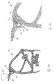
- the presentation of the Fig. 1 shows a hollow profile 10 according to the invention, which has a holding portion 12, a main portion 14 and a sealing lip portion 16.
- the holding section 12 is provided for fastening the hollow profile 10 on the end face of a groove of a door leaf of an inside pivoting door, cf. the Fig. 2 and 3 ,
- a projection 18 of the holding portion 12 is inserted into an undercut groove on the front side of the door leaf.
- Sealing lips 20 and 22 limit the holding portion 12 laterally and are in the mounted state on the outside or inside of the door leaf of the inner swing door.
- the main portion 14 extends between the holding portion 12 and the sealing lip portion 16 and is provided with a first hollow chamber 24 in which a first elastic switching profile 26 is arranged.
- the hollow chamber 24 may also be sealed on both sides and connected to a pressure sensor, for example a membrane switch.
- the first hollow chamber 24 is arranged between a first actuating web 28 and a second actuating web 30, wherein the first actuating web 28 and the second actuating web 30 are arranged in alignment with each other.
- the first actuating bar 28 extends from a contact area 32 on the in Fig. 1 The left outer surface of the main portion 32 to the hollow chamber 24.
- the second actuating bar 30 extends from the hollow chamber 24 to the holding portion 12.
- a third actuating bar 34 is between a portion of the second actuating bar 30, in which this is connected to the boundary of the hollow chamber 24 , and one in Fig. 1 Left outer surface of the main portion 14. If the hollow section 10 meets with the contact portion 32 to an obstacle, so this is the contact portion 32 in the Fig. 1 moved to the left or bottom left. This movement is transmitted to the boundary of the hollow chamber 24 by means of the first actuating web 28. A reaction force is applied from the second actuating bar 30, so that the hollow chamber 24 is compressed. In the same way, the electrical switching profile 26 compressed and a switching signal can be triggered.
- the hollow chamber 24 is sealed and connected to a pressure sensor, compressing the hollow chamber 24 generates a pressure surge or a pressure fluctuation which is detected by means of the pressure sensor, whereby a switching signal is generated.
- the third actuating bar 34 prevents buckling of the second actuating bar 30 in the load case described and thereby ensures that the hollow chamber 24 is reliably compressed in the event of a collision with the contact area 32.
- the contact region 32 projects beyond an imaginary extension 36, which is shown as a dashed line, of the outer surface of the holding section 12. In the illustration of FIG Fig. 1 the contact area 32 projects beyond the imaginary extension 36 on the right. This ensures, see also Fig.
- a sealing lip 38 is arranged, which is connected by means of a first web 40 and a second web 42 with the outer surface of the main portion 14 of the hollow section 10. Between the webs 40, 42, a second hollow chamber 44 is provided. Within the second hollow chamber 44, a second elastic switching profile 46 is arranged. Instead of the switching profile 46, the second hollow chamber 44 may be sealed and connected to a pressure sensor.
- the cavity 44 is shown slightly larger than an outer periphery of the electrical switching profile 46. This representation corresponds to reality, since between the switching profile 46 and the hollow chamber 44 a certain amount of play must be present in order to move the switching profile 46 into the hollow chamber 44 can. Also, a certain amount of play is necessary to eliminate the risk of false triggering.
- both the first web 40 and the second web 42 have a smooth outer surface and, seen in cross section, a continuous contour.
- a smooth outer surface means that the webs 40, 42 are not provided with grooves, notches, protrusions or the like.
- a continuous contour, seen in cross-section, means that, like Fig. 1 it can be seen, there is a continuous course of the contour of the outer surface and in particular no grooves, notches, sharp edges or shoulders with sharp edges in the contour of the outer surface of the two webs 40, 42 are present.
- Such a design of the webs 40, 42 facilitates the production of the hollow profile 40 and reduces a susceptibility to soiling of the hollow section 10 significantly.
- the outer surface of the second web 42 and the outer surface of the hollow profile 10 form an angle of 180 °.
- an outer surface of the sealing lip 38 and an outer surface of the second web 42 form an angle of approximately 70 °.
- an outer surface of the sealing lip 38 and an outer surface of the second web 42 form an angle of approximately 70 °.
- an outer surface of the sealing lip 38 and an outer surface of the second web 42 form an angle of approximately 70 °.
- an outer surface of the sealing lip 38 and an outer surface of the second web 42 form an angle of approximately 70 °.
- the region of a transition 58 between the first web 40 and the main portion 14th of the hollow section 10 include the outer surface of the first web 40 and the outer surface of the main portion 14 at an angle of about 80 °.
- the outer surface of the sealing lip 38 and the outer surface of the first web 40 form an angle of approximately 170 °.
- FIG. 2 shows schematically the sequence of movement when closing an inside swinging door with two door leaves 62, 64.
- Each of the door leaves 62, 64 is provided on its front side with a hollow profile according to the invention 66 and 68, wherein the hollow sections 66, 68 identical to the hollow section 10 of Fig. 1 are formed.
- a closing movement of the door leaves 62, 64, in Fig. 2 is represented by ten consecutive states
- the door leaf 62 is rotated about a pivot point 70 by means of a drive, not shown turned.
- the door leaf 64 is rotated about a pivot 72 by means of a drive, not shown.
- FIG. 2 can be seen that in the closed state of the door leaves 62, 64, the sealing lips 38 of the hollow sections 66, 68 touch each other and typically rest on each other. If an object or a human body part is clamped between the two sealing lips 38 when closing the door leaves 62, 64, this leads to a deflection of one or both sealing lips 38 and thereby to a compression of the second hollow chamber 44 and thus to a compression of the second switching profile 48 As a result, a switching signal can be generated and the drive of the door leaves 62 and / or 64 can be stopped or reversed.
- the presentation of the Fig. 3 shows a collision of the door panel 62 with the lower arm 74 of a passenger 76.
- the door panel 62 is provided in the same manner as the door panel 64 with a handle 78, which is engaged by the passenger 76 just entering. Now begins at this moment, the closing movement of the door panel 62 by rotation about the pivot point 70, the hollow profile 66 collides with its contact area 32 with the forearm 74 of the passenger 76.
- This collision as shown in FIG Fig. 1 has been explained, transmitted via the first actuating bar 28 on the first hollow chamber 24 and thereby the first switching profile 26. As a result, a switching signal can be generated and the drive of the door leaf 62 can be stopped or reversed.
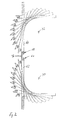
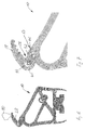
- the presentation of the 4 and 5 merely illustrate the networking of a computer model of the hollow section 10 of the Fig. 1 , By means of such a calculation model, the behavior of the hollow profile be simulated at external loads. Such calculation methods have long been state of the art.
- the 4 and 5 show the unloaded case of the hollow section 10, so according to the in Fig. 1 illustrated state.
- the representations of the 6 and 7 show a load case of the hollow section 10, wherein the sealing lip 38 in a clockwise direction, in the illustrations of 6 and 7 so to the right, is deflected. This can be done, for example, that the hollow section 10 with the sealing lip 38 on a in Fig. 6 schematically illustrated obstacle 80 impinges, for example, a human hand or the like.
- the sealing lip 38 is deflected in a clockwise direction.
- the second connecting web 42 is deformed and in particular moved inwards in the direction of the second hollow chamber 44.
- a deformation of the second web 42 is particularly strong in the region of the transition 56 between the sealing lip 38 and the second web 42.
- the second connecting web 52 is pressed strongly inward and thereby presses on the second switching profile 46, so that whose electrical conductors come into contact with each other and a switching signal is generated.
- the transition 56 is located approximately at the level of the center of the switching profile 46 and the center of the hollow chamber 44. It is Fig.
- the representations of the 8 and 9 show a further load case in which the sealing lip 38 meets the obstacle 80 and thereby against in a clockwise direction, in FIGS. 8 and 9 to the left, is deflected.
- the second connecting web 42 is only slightly deformed.
- the first connecting web 40 is strongly deformed in the region of the transition 58 between the outer surface of the first connecting web and the outer surface of the main portion of the hollow section 10 and pushed inwardly into the second hollow chamber 44.
- the inner surface of the first connecting web 40 thereby also presses on the switching profile 46, wherein the inner surface of the second connecting web 42 acts as an abutment, so that the electrical conductors of the switching profile 46 come into contact with each other and a switching signal can be generated.
- the transition 58 is located approximately at the level of the center of the switching profile 46 and the center of the hollow chamber 44. It is based on Fig. 9 to recognize that the first connecting web in the region of the transition 60 between the sealing lip 38 and the first connecting web 40 is not or only comparatively little deformed. Since the outer surface of the sealing lip 38 in the region of the transition 60 with the outer surface of the first connecting web 40 includes a significantly larger angle than in the region of the transition 58 between the first connecting web 40 and the main portion of the hollow section 10, the region of the transition 60 at the in the 8 and 9 shown load case significantly weaker deformed than in the transition 58.
- the representations of the 10 and 11 show a further load case, in which the sealing lip 38 as in the case of loading the 8 and 9 counterclockwise, but significantly further deflected.
- a load case can occur, for example, if, see Fig. 2 , with closed door leaves 62, 64 an object or a hand between the hollow sections 66, 68 is pushed through from the inside out.
- the transition 58 is advantageously arranged approximately at the level of the middle of the second hollow chamber 44. In a deflection of the sealing lip 38 in the counterclockwise direction thereby pushes the first connecting web in the region of the transition 58 approximately to the middle of the hollow chamber 44 into this and thus applied to the electrical switching profile 46 approximately in the middle. As a result, a reliable generation of a switching signal can be effected.
Landscapes
- Engineering & Computer Science (AREA)
- Mechanical Engineering (AREA)
- Seal Device For Vehicle (AREA)
- Specific Sealing Or Ventilating Devices For Doors And Windows (AREA)
Applications Claiming Priority (2)
| Application Number | Priority Date | Filing Date | Title |
|---|---|---|---|
| DE102013204022 | 2013-03-08 | ||
| DE102013205146.8A DE102013205146A1 (de) | 2013-03-08 | 2013-03-22 | Elastisches Hohlprofil |
Publications (3)
| Publication Number | Publication Date |
|---|---|
| EP2774796A2 true EP2774796A2 (fr) | 2014-09-10 |
| EP2774796A3 EP2774796A3 (fr) | 2015-11-04 |
| EP2774796B1 EP2774796B1 (fr) | 2020-07-15 |
Family
ID=50193291
Family Applications (1)
| Application Number | Title | Priority Date | Filing Date |
|---|---|---|---|
| EP14157183.6A Active EP2774796B1 (fr) | 2013-03-08 | 2014-02-28 | Profilé creux élastique |
Country Status (2)
| Country | Link |
|---|---|
| EP (1) | EP2774796B1 (fr) |
| DE (1) | DE102013205146A1 (fr) |
Families Citing this family (1)
| Publication number | Priority date | Publication date | Assignee | Title |
|---|---|---|---|---|
| DE102018219584B4 (de) * | 2018-11-15 | 2020-07-23 | Mayser Gmbh & Co. Kg | Hohlprofil für eine elektrische Schaltleiste und Fahrzeug mit einem Hohlprofil |
Family Cites Families (10)
| Publication number | Priority date | Publication date | Assignee | Title |
|---|---|---|---|---|
| US4133365A (en) * | 1977-06-08 | 1979-01-09 | Vapor Corporation | Obstruction sensing edge for a bifolding door |
| DE9321338U1 (de) * | 1993-08-09 | 1997-06-12 | Metzeler Automotive Profiles Gmbh, 88131 Lindau | Einklemmschutz für kraftbetätigte Schließeinrichtungen |
| DE102004005289A1 (de) * | 2004-02-03 | 2005-08-25 | Gummi-Welz Gmbh & Co. Kg | Fingerschutzleiste mit elektrischem Schaltkontakt |
| DE202004014861U1 (de) * | 2004-09-23 | 2004-12-23 | Gummi-Welz Gmbh & Co. Kg | Fingerschutzleiste mit elektrischem Schaltkontakt |
| ATE447504T1 (de) | 2004-02-03 | 2009-11-15 | Gummi Welz Gmbh U Co Kg Gummi | Fingerschutzleiste mit elektrischem schaltkontakt gegen einklemmen |
| DE102007002745A1 (de) | 2006-01-19 | 2007-07-26 | Daimlerchrysler Ag | Fingerschutzleiste, insbesondere für Innenschwenktüren |
| DE202006010582U1 (de) * | 2006-07-08 | 2006-09-14 | Gummi-Welz Gmbh & Co. Kg | Fingerschutzleiste, insbesondere für Außen- und Innenschwenktüren |
| DE102008050897A1 (de) * | 2007-09-27 | 2009-07-02 | Mayser Gmbh & Co. Kg | Profil für Sensoren und Sensor zum berührungslosen Erfassen von Gegenständen |
| DE202008011477U1 (de) | 2008-08-28 | 2008-11-06 | Daimler Ag | Fingerschutzleiste, insbesondere für Aussenschwing- und Schwenkschiebetüren |
| DE202008013508U1 (de) * | 2008-10-10 | 2009-01-08 | Gummi-Welz Gmbh U. Co. Kg Gummi-Kunststofftechnik-Schaumstoffe | Profilleiste für eine Fahrzeugtür mit Einklemmschutz |
-
2013
- 2013-03-22 DE DE102013205146.8A patent/DE102013205146A1/de not_active Withdrawn
-
2014
- 2014-02-28 EP EP14157183.6A patent/EP2774796B1/fr active Active
Also Published As
| Publication number | Publication date |
|---|---|
| EP2774796A3 (fr) | 2015-11-04 |
| DE102013205146A1 (de) | 2014-09-11 |
| EP2774796B1 (fr) | 2020-07-15 |
Similar Documents
| Publication | Publication Date | Title |
|---|---|---|
| DE102010039157A1 (de) | Schienenlängsführung | |
| WO2018060226A1 (fr) | Ensemble serrure de véhicule automobile | |
| EP3847332B1 (fr) | Dispositif de protection pour un battant de porte pour un véhicule et dispositif de porte pour un véhicule | |
| EP1876048B1 (fr) | Baguette de protection de doigts, en particulier pour des portes basculant vers lýextérieur et lýintérieur | |
| EP2827743B1 (fr) | Corps porteur de dents | |
| EP2532820B1 (fr) | Profilé creux pour un interrupteur de bordure et procédé de détection d'obstacles avec un tel interrupteur de bordure. | |
| EP1811118B1 (fr) | Baguette de protection de doigts, en particulier pour des portes basculant vers l'intérieur | |
| EP1526241A1 (fr) | Arrangement anti-pincement et moule d'injection | |
| EP2383136B1 (fr) | Joint d'étanchéité pour une porte de véhicule | |
| EP2774796B1 (fr) | Profilé creux élastique | |
| DE102010017441A1 (de) | Dichtungseinrichtung für eine Fahrzeugtür | |
| DE102007002745A1 (de) | Fingerschutzleiste, insbesondere für Innenschwenktüren | |
| EP0280191A1 (fr) | Sécurité antipincement pour une porte | |
| DE19745180B4 (de) | Andrückvorrichtung zwischen einem Flügel und einem Blendrahmen einer Tür, eines Fensters oder dergleichen | |
| EP3188919A1 (fr) | Dispositif d'étanchéité pour porte, système d'étanchéité pour porte et battant de porte pour véhicule ferroviaire | |
| DE102013205149A1 (de) | Elastisches Hohlprofil und Innenschwenktüre mit einem elastischen Hohlprofil | |
| DE102004005289A1 (de) | Fingerschutzleiste mit elektrischem Schaltkontakt | |
| DE29710499U1 (de) | Sicherheitsvorrichtung für verschiebbare Fensterscheiben | |
| DE102009007407A1 (de) | Vorrichtung zur Höhenverstellung des Umlenkbeschlages von Sicherheitsgurten | |
| AT502951B1 (de) | Schaltprofil | |
| WO2008031472A1 (fr) | Dispositif d'agencement mobile d'une porte coulissante | |
| EP3421710B1 (fr) | Étanchéité pour une porte se fermant hermétiquement | |
| DE202004014861U1 (de) | Fingerschutzleiste mit elektrischem Schaltkontakt | |
| WO2018029342A1 (fr) | Dispositif de sécurité de bord de fermeture avec préchambre | |
| EP3261106B1 (fr) | Système de protection contre le pincement à installer sur une partie de véhicule |
Legal Events
| Date | Code | Title | Description |
|---|---|---|---|
| PUAI | Public reference made under article 153(3) epc to a published international application that has entered the european phase |
Free format text: ORIGINAL CODE: 0009012 |
|
| 17P | Request for examination filed |
Effective date: 20140228 |
|
| AK | Designated contracting states |
Kind code of ref document: A2 Designated state(s): AL AT BE BG CH CY CZ DE DK EE ES FI FR GB GR HR HU IE IS IT LI LT LU LV MC MK MT NL NO PL PT RO RS SE SI SK SM TR |
|
| AX | Request for extension of the european patent |
Extension state: BA ME |
|
| RAP1 | Party data changed (applicant data changed or rights of an application transferred) |
Owner name: MAYSER HOLDING GMBH & CO. KG |
|
| PUAL | Search report despatched |
Free format text: ORIGINAL CODE: 0009013 |
|
| AK | Designated contracting states |
Kind code of ref document: A3 Designated state(s): AL AT BE BG CH CY CZ DE DK EE ES FI FR GB GR HR HU IE IS IT LI LT LU LV MC MK MT NL NO PL PT RO RS SE SI SK SM TR |
|
| AX | Request for extension of the european patent |
Extension state: BA ME |
|
| R17P | Request for examination filed (corrected) |
Effective date: 20160504 |
|
| RBV | Designated contracting states (corrected) |
Designated state(s): AL AT BE BG CH CY CZ DE DK EE ES FI FR GB GR HR HU IE IS IT LI LT LU LV MC MK MT NL NO PL PT RO RS SE SI SK SM TR |
|
| STAA | Information on the status of an ep patent application or granted ep patent |
Free format text: STATUS: EXAMINATION IS IN PROGRESS |
|
| 17Q | First examination report despatched |
Effective date: 20190618 |
|
| REG | Reference to a national code |
Ref country code: DE Ref legal event code: R079 Ref document number: 502014014442 Country of ref document: DE Free format text: PREVIOUS MAIN CLASS: B60J0010000000 Ipc: E05F0015000000 |
|
| GRAP | Despatch of communication of intention to grant a patent |
Free format text: ORIGINAL CODE: EPIDOSNIGR1 |
|
| STAA | Information on the status of an ep patent application or granted ep patent |
Free format text: STATUS: GRANT OF PATENT IS INTENDED |
|
| RIC1 | Information provided on ipc code assigned before grant |
Ipc: E05F 15/44 20150101ALI20200130BHEP Ipc: E05F 15/40 20150101ALI20200130BHEP Ipc: E05F 15/00 20150101AFI20200130BHEP Ipc: B60J 10/86 20160101ALI20200130BHEP Ipc: E06B 7/36 20060101ALI20200130BHEP Ipc: B60J 10/248 20160101ALI20200130BHEP |
|
| INTG | Intention to grant announced |
Effective date: 20200218 |
|
| GRAS | Grant fee paid |
Free format text: ORIGINAL CODE: EPIDOSNIGR3 |
|
| GRAA | (expected) grant |
Free format text: ORIGINAL CODE: 0009210 |
|
| STAA | Information on the status of an ep patent application or granted ep patent |
Free format text: STATUS: THE PATENT HAS BEEN GRANTED |
|
| AK | Designated contracting states |
Kind code of ref document: B1 Designated state(s): AL AT BE BG CH CY CZ DE DK EE ES FI FR GB GR HR HU IE IS IT LI LT LU LV MC MK MT NL NO PL PT RO RS SE SI SK SM TR |
|
| REG | Reference to a national code |
Ref country code: GB Ref legal event code: FG4D Free format text: NOT ENGLISH Ref country code: CH Ref legal event code: EP |
|
| REG | Reference to a national code |
Ref country code: DE Ref legal event code: R096 Ref document number: 502014014442 Country of ref document: DE |
|
| REG | Reference to a national code |
Ref country code: IE Ref legal event code: FG4D Free format text: LANGUAGE OF EP DOCUMENT: GERMAN |
|
| REG | Reference to a national code |
Ref country code: AT Ref legal event code: REF Ref document number: 1291218 Country of ref document: AT Kind code of ref document: T Effective date: 20200815 |
|
| REG | Reference to a national code |
Ref country code: NL Ref legal event code: FP |
|
| REG | Reference to a national code |
Ref country code: LT Ref legal event code: MG4D |
|
| PG25 | Lapsed in a contracting state [announced via postgrant information from national office to epo] |
Ref country code: ES Free format text: LAPSE BECAUSE OF FAILURE TO SUBMIT A TRANSLATION OF THE DESCRIPTION OR TO PAY THE FEE WITHIN THE PRESCRIBED TIME-LIMIT Effective date: 20200715 Ref country code: NO Free format text: LAPSE BECAUSE OF FAILURE TO SUBMIT A TRANSLATION OF THE DESCRIPTION OR TO PAY THE FEE WITHIN THE PRESCRIBED TIME-LIMIT Effective date: 20201015 Ref country code: FI Free format text: LAPSE BECAUSE OF FAILURE TO SUBMIT A TRANSLATION OF THE DESCRIPTION OR TO PAY THE FEE WITHIN THE PRESCRIBED TIME-LIMIT Effective date: 20200715 Ref country code: GR Free format text: LAPSE BECAUSE OF FAILURE TO SUBMIT A TRANSLATION OF THE DESCRIPTION OR TO PAY THE FEE WITHIN THE PRESCRIBED TIME-LIMIT Effective date: 20201016 Ref country code: BG Free format text: LAPSE BECAUSE OF FAILURE TO SUBMIT A TRANSLATION OF THE DESCRIPTION OR TO PAY THE FEE WITHIN THE PRESCRIBED TIME-LIMIT Effective date: 20201015 Ref country code: SE Free format text: LAPSE BECAUSE OF FAILURE TO SUBMIT A TRANSLATION OF THE DESCRIPTION OR TO PAY THE FEE WITHIN THE PRESCRIBED TIME-LIMIT Effective date: 20200715 Ref country code: LT Free format text: LAPSE BECAUSE OF FAILURE TO SUBMIT A TRANSLATION OF THE DESCRIPTION OR TO PAY THE FEE WITHIN THE PRESCRIBED TIME-LIMIT Effective date: 20200715 Ref country code: HR Free format text: LAPSE BECAUSE OF FAILURE TO SUBMIT A TRANSLATION OF THE DESCRIPTION OR TO PAY THE FEE WITHIN THE PRESCRIBED TIME-LIMIT Effective date: 20200715 Ref country code: PT Free format text: LAPSE BECAUSE OF FAILURE TO SUBMIT A TRANSLATION OF THE DESCRIPTION OR TO PAY THE FEE WITHIN THE PRESCRIBED TIME-LIMIT Effective date: 20201116 |
|
| PG25 | Lapsed in a contracting state [announced via postgrant information from national office to epo] |
Ref country code: IS Free format text: LAPSE BECAUSE OF FAILURE TO SUBMIT A TRANSLATION OF THE DESCRIPTION OR TO PAY THE FEE WITHIN THE PRESCRIBED TIME-LIMIT Effective date: 20201115 Ref country code: PL Free format text: LAPSE BECAUSE OF FAILURE TO SUBMIT A TRANSLATION OF THE DESCRIPTION OR TO PAY THE FEE WITHIN THE PRESCRIBED TIME-LIMIT Effective date: 20200715 Ref country code: RS Free format text: LAPSE BECAUSE OF FAILURE TO SUBMIT A TRANSLATION OF THE DESCRIPTION OR TO PAY THE FEE WITHIN THE PRESCRIBED TIME-LIMIT Effective date: 20200715 Ref country code: LV Free format text: LAPSE BECAUSE OF FAILURE TO SUBMIT A TRANSLATION OF THE DESCRIPTION OR TO PAY THE FEE WITHIN THE PRESCRIBED TIME-LIMIT Effective date: 20200715 |
|
| REG | Reference to a national code |
Ref country code: DE Ref legal event code: R097 Ref document number: 502014014442 Country of ref document: DE |
|
| PG25 | Lapsed in a contracting state [announced via postgrant information from national office to epo] |
Ref country code: RO Free format text: LAPSE BECAUSE OF FAILURE TO SUBMIT A TRANSLATION OF THE DESCRIPTION OR TO PAY THE FEE WITHIN THE PRESCRIBED TIME-LIMIT Effective date: 20200715 Ref country code: SM Free format text: LAPSE BECAUSE OF FAILURE TO SUBMIT A TRANSLATION OF THE DESCRIPTION OR TO PAY THE FEE WITHIN THE PRESCRIBED TIME-LIMIT Effective date: 20200715 Ref country code: IT Free format text: LAPSE BECAUSE OF FAILURE TO SUBMIT A TRANSLATION OF THE DESCRIPTION OR TO PAY THE FEE WITHIN THE PRESCRIBED TIME-LIMIT Effective date: 20200715 Ref country code: CZ Free format text: LAPSE BECAUSE OF FAILURE TO SUBMIT A TRANSLATION OF THE DESCRIPTION OR TO PAY THE FEE WITHIN THE PRESCRIBED TIME-LIMIT Effective date: 20200715 Ref country code: DK Free format text: LAPSE BECAUSE OF FAILURE TO SUBMIT A TRANSLATION OF THE DESCRIPTION OR TO PAY THE FEE WITHIN THE PRESCRIBED TIME-LIMIT Effective date: 20200715 Ref country code: EE Free format text: LAPSE BECAUSE OF FAILURE TO SUBMIT A TRANSLATION OF THE DESCRIPTION OR TO PAY THE FEE WITHIN THE PRESCRIBED TIME-LIMIT Effective date: 20200715 |
|
| PLBE | No opposition filed within time limit |
Free format text: ORIGINAL CODE: 0009261 |
|
| STAA | Information on the status of an ep patent application or granted ep patent |
Free format text: STATUS: NO OPPOSITION FILED WITHIN TIME LIMIT |
|
| PG25 | Lapsed in a contracting state [announced via postgrant information from national office to epo] |
Ref country code: AL Free format text: LAPSE BECAUSE OF FAILURE TO SUBMIT A TRANSLATION OF THE DESCRIPTION OR TO PAY THE FEE WITHIN THE PRESCRIBED TIME-LIMIT Effective date: 20200715 |
|
| 26N | No opposition filed |
Effective date: 20210416 |
|
| PG25 | Lapsed in a contracting state [announced via postgrant information from national office to epo] |
Ref country code: SK Free format text: LAPSE BECAUSE OF FAILURE TO SUBMIT A TRANSLATION OF THE DESCRIPTION OR TO PAY THE FEE WITHIN THE PRESCRIBED TIME-LIMIT Effective date: 20200715 |
|
| PG25 | Lapsed in a contracting state [announced via postgrant information from national office to epo] |
Ref country code: SI Free format text: LAPSE BECAUSE OF FAILURE TO SUBMIT A TRANSLATION OF THE DESCRIPTION OR TO PAY THE FEE WITHIN THE PRESCRIBED TIME-LIMIT Effective date: 20200715 |
|
| PG25 | Lapsed in a contracting state [announced via postgrant information from national office to epo] |
Ref country code: MC Free format text: LAPSE BECAUSE OF FAILURE TO SUBMIT A TRANSLATION OF THE DESCRIPTION OR TO PAY THE FEE WITHIN THE PRESCRIBED TIME-LIMIT Effective date: 20200715 |
|
| PG25 | Lapsed in a contracting state [announced via postgrant information from national office to epo] |
Ref country code: LI Free format text: LAPSE BECAUSE OF NON-PAYMENT OF DUE FEES Effective date: 20210228 Ref country code: LU Free format text: LAPSE BECAUSE OF NON-PAYMENT OF DUE FEES Effective date: 20210228 Ref country code: CH Free format text: LAPSE BECAUSE OF NON-PAYMENT OF DUE FEES Effective date: 20210228 |
|
| PG25 | Lapsed in a contracting state [announced via postgrant information from national office to epo] |
Ref country code: IE Free format text: LAPSE BECAUSE OF NON-PAYMENT OF DUE FEES Effective date: 20210228 |
|
| REG | Reference to a national code |
Ref country code: AT Ref legal event code: MM01 Ref document number: 1291218 Country of ref document: AT Kind code of ref document: T Effective date: 20210228 |
|
| PG25 | Lapsed in a contracting state [announced via postgrant information from national office to epo] |
Ref country code: AT Free format text: LAPSE BECAUSE OF NON-PAYMENT OF DUE FEES Effective date: 20210228 |
|
| PGFP | Annual fee paid to national office [announced via postgrant information from national office to epo] |
Ref country code: NL Payment date: 20230220 Year of fee payment: 10 |
|
| PGFP | Annual fee paid to national office [announced via postgrant information from national office to epo] |
Ref country code: FR Payment date: 20230217 Year of fee payment: 10 |
|
| PG25 | Lapsed in a contracting state [announced via postgrant information from national office to epo] |
Ref country code: HU Free format text: LAPSE BECAUSE OF FAILURE TO SUBMIT A TRANSLATION OF THE DESCRIPTION OR TO PAY THE FEE WITHIN THE PRESCRIBED TIME-LIMIT; INVALID AB INITIO Effective date: 20140228 |
|
| PGFP | Annual fee paid to national office [announced via postgrant information from national office to epo] |
Ref country code: TR Payment date: 20230227 Year of fee payment: 10 Ref country code: GB Payment date: 20230221 Year of fee payment: 10 Ref country code: DE Payment date: 20230223 Year of fee payment: 10 Ref country code: BE Payment date: 20230220 Year of fee payment: 10 |
|
| PG25 | Lapsed in a contracting state [announced via postgrant information from national office to epo] |
Ref country code: CY Free format text: LAPSE BECAUSE OF FAILURE TO SUBMIT A TRANSLATION OF THE DESCRIPTION OR TO PAY THE FEE WITHIN THE PRESCRIBED TIME-LIMIT Effective date: 20200715 |
|
| PG25 | Lapsed in a contracting state [announced via postgrant information from national office to epo] |
Ref country code: MK Free format text: LAPSE BECAUSE OF FAILURE TO SUBMIT A TRANSLATION OF THE DESCRIPTION OR TO PAY THE FEE WITHIN THE PRESCRIBED TIME-LIMIT Effective date: 20200715 |
|
| REG | Reference to a national code |
Ref country code: DE Ref legal event code: R119 Ref document number: 502014014442 Country of ref document: DE |
|
| PG25 | Lapsed in a contracting state [announced via postgrant information from national office to epo] |
Ref country code: MT Free format text: LAPSE BECAUSE OF FAILURE TO SUBMIT A TRANSLATION OF THE DESCRIPTION OR TO PAY THE FEE WITHIN THE PRESCRIBED TIME-LIMIT Effective date: 20200715 |
|
| REG | Reference to a national code |
Ref country code: NL Ref legal event code: MM Effective date: 20240301 |
|
| GBPC | Gb: european patent ceased through non-payment of renewal fee |
Effective date: 20240228 |
|
| PG25 | Lapsed in a contracting state [announced via postgrant information from national office to epo] |
Ref country code: NL Free format text: LAPSE BECAUSE OF NON-PAYMENT OF DUE FEES Effective date: 20240301 |
|
| PG25 | Lapsed in a contracting state [announced via postgrant information from national office to epo] |
Ref country code: NL Free format text: LAPSE BECAUSE OF NON-PAYMENT OF DUE FEES Effective date: 20240301 |
|
| REG | Reference to a national code |
Ref country code: BE Ref legal event code: MM Effective date: 20240229 |
|
| PG25 | Lapsed in a contracting state [announced via postgrant information from national office to epo] |
Ref country code: DE Free format text: LAPSE BECAUSE OF NON-PAYMENT OF DUE FEES Effective date: 20240903 |
|
| PG25 | Lapsed in a contracting state [announced via postgrant information from national office to epo] |
Ref country code: BE Free format text: LAPSE BECAUSE OF NON-PAYMENT OF DUE FEES Effective date: 20240229 |
|
| PG25 | Lapsed in a contracting state [announced via postgrant information from national office to epo] |
Ref country code: GB Free format text: LAPSE BECAUSE OF NON-PAYMENT OF DUE FEES Effective date: 20240228 |
|
| PG25 | Lapsed in a contracting state [announced via postgrant information from national office to epo] |
Ref country code: FR Free format text: LAPSE BECAUSE OF NON-PAYMENT OF DUE FEES Effective date: 20240229 |
|
| PG25 | Lapsed in a contracting state [announced via postgrant information from national office to epo] |
Ref country code: GB Free format text: LAPSE BECAUSE OF NON-PAYMENT OF DUE FEES Effective date: 20240228 Ref country code: FR Free format text: LAPSE BECAUSE OF NON-PAYMENT OF DUE FEES Effective date: 20240229 Ref country code: DE Free format text: LAPSE BECAUSE OF NON-PAYMENT OF DUE FEES Effective date: 20240903 Ref country code: BE Free format text: LAPSE BECAUSE OF NON-PAYMENT OF DUE FEES Effective date: 20240229 |