EP2774845B1 - System und Verfahren zur adaptiven Regelung der Rotorgeschwindigkeit für optimale Leistung - Google Patents
System und Verfahren zur adaptiven Regelung der Rotorgeschwindigkeit für optimale Leistung Download PDFInfo
- Publication number
- EP2774845B1 EP2774845B1 EP13171079.0A EP13171079A EP2774845B1 EP 2774845 B1 EP2774845 B1 EP 2774845B1 EP 13171079 A EP13171079 A EP 13171079A EP 2774845 B1 EP2774845 B1 EP 2774845B1
- Authority
- EP
- European Patent Office
- Prior art keywords
- rotor
- engine
- power available
- increasing
- limit
- Prior art date
- Legal status (The legal status is an assumption and is not a legal conclusion. Google has not performed a legal analysis and makes no representation as to the accuracy of the status listed.)
- Active
Links
Images

Classifications
-
- B—PERFORMING OPERATIONS; TRANSPORTING
- B64—AIRCRAFT; AVIATION; COSMONAUTICS
- B64C—AEROPLANES; HELICOPTERS
- B64C27/00—Rotorcraft; Rotors peculiar thereto
- B64C27/04—Helicopters
-
- B—PERFORMING OPERATIONS; TRANSPORTING
- B64—AIRCRAFT; AVIATION; COSMONAUTICS
- B64C—AEROPLANES; HELICOPTERS
- B64C27/00—Rotorcraft; Rotors peculiar thereto
- B64C27/54—Mechanisms for controlling blade adjustment or movement relative to rotor head, e.g. lag-lead movement
- B64C27/56—Mechanisms for controlling blade adjustment or movement relative to rotor head, e.g. lag-lead movement characterised by the control initiating means, e.g. manually actuated
- B64C27/57—Mechanisms for controlling blade adjustment or movement relative to rotor head, e.g. lag-lead movement characterised by the control initiating means, e.g. manually actuated automatic or condition responsive, e.g. responsive to rotor speed, torque or thrust
-
- B—PERFORMING OPERATIONS; TRANSPORTING
- B64—AIRCRAFT; AVIATION; COSMONAUTICS
- B64D—EQUIPMENT FOR FITTING IN OR TO AIRCRAFT; FLIGHT SUITS; PARACHUTES; ARRANGEMENT OR MOUNTING OF POWER PLANTS OR PROPULSION TRANSMISSIONS IN AIRCRAFT
- B64D31/00—Power plant control systems; Arrangement of power plant control systems in aircraft
- B64D31/02—Initiating means
- B64D31/06—Initiating means actuated automatically
Definitions
- the present disclosure relates to a system and method adaptively governing a rotor speed for optimal performance of an aircraft.
- variable rotor speed rotorcraft have been developed to a limited extent.
- Variable rotorcraft have been limited to certain settings, such as a "high performance” setting in which the pilot could have the rotor speed increased in a high altitude and/or hot ambient condition.
- a "quiet mode” setting could be chosen to reduce rotor speed in order to reduce aircraft noise in forward flight.
- a system and method for the governing of rotor speed in order to optimize performance of the aircraft.
- the devices, members, apparatuses, etc. described herein may be positioned in any desired orientation.
- the use of terms such as “above,” “below,” “upper,” “lower,” or other like terms to describe a spatial relationship between various components or to describe the spatial orientation of aspects of such components should be understood to describe a relative relationship between the components or a spatial orientation of aspects of such components, respectively, as the device described herein may be oriented in any desired direction.
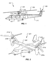
- Rotorcraft 101 has a rotor system 103 with a plurality of rotor blades 105.
- the pitch of each rotor blade 105 can be managed in order to selectively control direction, thrust, and lift of rotorcraft 101.
- a swashplate mechanism 123 can be used to collectively and/or cyclically change the pitch of rotor blades 105.
- Rotorcraft 101 further includes a fuselage 107, anti-torque system 109, and an empennage 111. Torque is supplied to rotor system 103 and anti-torque system 109 with at least one engine 113.
- a main rotor gearbox 115 is operably associated with an engine main output driveshaft 121 and the main rotor mast.
- Tilt rotor aircraft 201 can include nacelles 203a and 203b, a wing 205, a fuselage 207, and a tail member 209.
- Each nacelle 203a and 203b can include an engine and gearbox for driving rotor systems 211a and 211b, respectively.
- Nacelles 203a and 203b are each configured to rotate between a helicopter mode, in which the nacelles 203a and 203b are approximately vertical, and an airplane mode, in which the nacelles 203a and 203b are approximately horizontal.
- Rotorcraft 101 and tilt rotor aircraft 201 are merely illustrative of the wide variety of aircraft and vehicles that are particularly well suited to take advantage of the method and system of the present disclosure. It should be appreciated that other aircraft can also utilize the method and system of the present disclosure to optimize performance.
- system 301 is illustrated in conjunction with rotorcraft 101. It should be appreciated that though system 301 is illustrated with regard to rotorcraft 101, system 301 is equally implementable on tilt rotor aircraft 201, as well as other aircraft. Further, it should be appreciated that system 301 can be implemented in a wide variety of configurations, depending in part on the flight control configuration of the aircraft.
- System 301 is particularly well suited for implementation in aircraft having a fly-by-wire flight control computer, such as flight control computer 125; however, non fly-by-wire aircraft can also utilize system 301.
- system 301 can be utilized in a flight control system having collective actuators that can receive commands from a trim motor, autopilot system, or any other system that allows collective commands to be realized by collective actuators.
- system is particularly well suited for implementation with aircraft having an engine controlled by an engine control unit 127, such as a FADEC (full authority digital engine control) system.
- system 301 can also be implemented on an aircraft having an engine that is not controlled by an engine control unit 127, in such an embodiment, system 301 can make fuel control commands directly to a fuel control unit 129, for example.
- System 301 is configured to command the rotor speed to an optimal rotor speed by calculating power available based upon engine parameters, engine limits, gearbox limits, and rotor parameters.
- the calculated optimal rotor speed can be a setpoint for a rotor speed governor.
- system 301 is configured to calculate and command an optimal rotor speed (max performance) using a combination of collective rotor pitch governing and engine governing.
- system 301 is particularly well suited for calculating and commanding an optimal rotor speed during an OEI (one engine inoperable) condition on a multi-engine rotorcraft; however, system can also be utilized to calculate and command an optimal rotor speed during normal engine operating conditions for both single engine and multi-engine aircraft.
- OEI one engine inoperable
- System 301 is preferably integrated with flight control computer 125; however, in another embodiment system 301 can be a standalone computer system within the aircraft.
- System 301 can include a processor 303 configured for processing receivable data in an algorithm 501 and subsequently making commands to adaptively affect rotor speed.
- Processor 303 can receive real time operational data from sensors, instrumentation, and the like.
- Processor 303 can receive real time data pertaining to an engine exhaust temperature (MGT) 305, a transmission (i.e. gearbox 115) torque (Qe) 307, an engine gas generator speed (Ng) 309, and a rotor speed (Nr) 311.
- Allowable engine limits such as an engine exhaust temperature (MGT) limit 313 and an engine gas generator speed (Ng) limit 317, as well as a transmission (i.e. gearbox 115) torque (Qe) limit 315, are in data communication with processor 313.
- Allowable engine limits 313, 317, and transmission limit 315 can be stored in a database within processor, or be stored remotely, as long as limits 313, 315, and 317 are available for the analysis.
- Processor 303 is configured to perform analysis using an optimization algorithm 501 and subsequently make a rotor pitch command 315 and/or an engine speed command 317.
- Algorithm 501 can be performed when either the actual transmission torque (Qe) 307 is approximately limited at the transmission torque (Qe) limit 315, or when an engine parameter, such as the engine exhaust temperature (MGT) 305 or the engine gas generator speed (Ng) 309 is approximately limited at the engine exhaust temperature (MGT) limit 313 or the engine gas generator speed (Ng) limit 317, respectively.
- Flight control computer 125 can be configured to increase power (i.e. thrust) on demand by increasing engine and/or rotor speed until one of the above limits is reached, at which point in time algorithm 501 can be performed to dictate steps to further utilize power available.
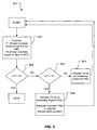
- Algorithm 501 includes a step 503 for calculating power available P1 based upon transmission torque (Qe) and rotor speed (Nr) by comparing each of Qe and Nr to their respective limits. Further, step 503 can include calculating power available P2 based upon engine gas generator speed (Ng) and engine exhaust temperature (MGT) by comparing each of Ng and MGT to their respective limits.
- step 503 can include calculating power available P2 based upon engine gas generator speed (Ng) and engine exhaust temperature (MGT) by comparing each of Ng and MGT to their respective limits.
- a step 505 analyzes whether P1 is equal to P2. If the result of step 505 is yes, then the algorithm stops. If the result of step 505 is no, then the algorithm proceeds to step 507.
- Step 507 analyzes whether P1 is greater than P2. If the result of step 507 is yes, then the algorithm proceeds to step 509.
- Step 509 includes increasing thrust by increasing engine power. Step 509 can include modulating collective pitch to keep transmission torque (Qe) approximately constant. As a result to increasing engine power in step 509, thrust increases, rotor speed (Nr) increases, transmission torque (Qe) remains constant, engine exhaust temperature (MGT) increases, and engine gas generator speed (Ng) increases.
- Nr the power is not increased to the extent that would cause any of the limits associated with Nr, Qe, MGT, or Ng to be exceeded.
- the increase in engine power, and consequently rotor speed (Nr) can be implemented by increasing the amount of fuel sent to engine 113.
- the algorithm can proceed back to start.
- Step 511 includes increasing thrust by increasing collective pitch.
- transmission torque (Qe) increases, rotor speed (Nr) decreases, engine power remains constant, engine exhaust temperature (MGT) remains constant, and engine gas generator speed (Ng) remains constant.
- MCT engine exhaust temperature
- Ng engine gas generator speed
- the collective pitch is not increased to the extent that would cause transmission torque (Qe) to exceed the transmission torque (Qe) limit. The algorithm can proceed back to start.
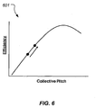
- a graph 601 graphically depicts an exemplary relationship between efficiency and collective pitch, and thus how an increase in collective pitch can improve aerodynamic efficiency, thereby providing a net thrust increase even though the rotor speed (Nr) is decreased.
- Implementation of system 301 and method 501 can optimize performance of an aircraft by governing rotor speed in accordance with a given power available.
- the optimal rotor speed is calculated and governed automatically and seamlessly so that pilot selection is not required.
- the optimal rotor speed can be calculated and governed during all operating conditions and flight envelopes such that increased performance in one area of the flight envelope does not result in decreased performance in another area of the flight envelope.
- the optimal rotor speed can be anywhere within a specified range, rather than a few specified values. For example, if the specified rotor speed ranges from 92% to 105% (100% being nominal rotor speed), then the governed rotor speed can be anywhere with the range.
- the system and method can include methodology to prevent the rotor speed from dwelling at a resonant frequency.
- system 301 and method 501 includes the increase of aircraft gross weight capability.
- the aircraft is conventional certified in accordance with the performance capability in a one engine inoperably (OEI) state.
- OEI one engine inoperably
- a "Category A” certification can define how the aircraft can perform in an OEI condition.
- "Category A” certification can outline how the aircraft would land safe or fly safe in an OEI condition.
- Such a "Category A” certification can be a limiting factor in the allowable gross weight determination for a certain flight regime.
- implementation of system 301 and method 501 allows the aircraft to take advantage of additional power available and increase thrust during the OEI condition, thereby increasing the allowable gross weight of the aircraft.
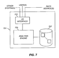
- System 701 is schematically illustrated.
- System 701 is configured for performing one or more functions with regard to the operation of system 301 and algorithm 501, further disclosed herein. Further, any processing and analysis can be partly or fully performed by computer system 701. Computer system 701 can be partly or fully integrated with other aircraft computer systems.
- the system 701 can include an input/output (I/O) interface 703, an analysis engine 705, and a database 707. Alternative embodiments can combine or distribute the input/output (I/O) interface 703, analysis engine 705, and database 707, as desired.
- Embodiments of the system 701 can include one or more computers that include one or more processors and memories configured for performing tasks described herein. This can include, for example, a computer having a central processing unit (CPU) and non-volatile memory that stores software instructions for instructing the CPU to perform at least some of the tasks described herein.
- CPU central processing unit
- This can also include, for example, two or more computers that are in communication via a computer network, where one or more of the computers include a CPU and non-volatile memory, and one or more of the computer's non-volatile memory stores software instructions for instructing any of the CPU(s) to perform any of the tasks described herein.
- the exemplary embodiment is described in terms of a discrete machine, it should be appreciated that this description is non-limiting, and that the present description applies equally to numerous other arrangements involving one or more machines performing tasks distributed in any way among the one or more machines. It should also be appreciated that such machines need not be dedicated to performing tasks described herein, but instead can be multi-purpose machines, for example computer workstations, that are suitable for also performing other tasks.
- the I/O interface 703 can provide a communication link between external users, systems, and data sources and components of the system 701.
- the I/O interface 703 can be configured for allowing one or more users to input information to the system 701 via any known input device. Examples can include a keyboard, mouse, touch screen, and/or any other desired input device.
- the I/O interface 703 can be configured for allowing one or more users to receive information output from the system 701 via any known output device. Examples can include a display monitor, a printer, cockpit display, and/or any other desired output device.
- the I/O interface 703 can be configured for allowing other systems to communicate with the system 701.
- the I/O interface 703 can allow one or more remote computer(s) to access information, input information, and/or remotely instruct the system 701 to perform one or more of the tasks described herein.
- the I/O interface 703 can be configured for allowing communication with one or more remote data sources.
- the I/O interface 703 can allow one or more remote data source(s) to access information, input information, and/or remotely instruct the system 701 to perform one or more of the tasks described herein.
- the database 707 provides persistent data storage for system 701. While the term "database" is primarily used, a memory or other suitable data storage arrangement may provide the functionality of the database 707. In alternative embodiments, the database 707 can be integral to or separate from the system 701 and can operate on one or more computers. The database 707 preferably provides non-volatile data storage for any information suitable to support the operation of system 301 and method 501, including various types of data discussed further herein.
- the analysis engine 705 can include various combinations of one or more processors, memories, and software components.
Landscapes
- Engineering & Computer Science (AREA)
- Aviation & Aerospace Engineering (AREA)
- Mechanical Engineering (AREA)
- Control Of Vehicle Engines Or Engines For Specific Uses (AREA)
- Combined Controls Of Internal Combustion Engines (AREA)
Claims (15)
- Ein Verfahren zur adaptiven Regelung einer Drehgeschwindigkeit eines Rotors in einem Fluggerät (101, 201), das Verfahren weist dabei Folgendes auf:die Berechnung einer ersten verfügbaren Leistung durch den Vergleich eines aktuellen Übertragungsdrehmoments (307) mit einem Übertragungsdrehmoment-Grenzwert (315);die Berechnung einer zweiten verfügbaren Leistung durch Vergleich einer aktuellen Triebwerk-Abgastemperatur (305) mit einem Triebwerk-Abgastemperatur-Grenzwert (313);den Vergleich der ersten verfügbaren Leistung mit der zweiten verfügbaren Leistung; unddie Erhöhung einer Schubkraft durch die Erhöhung einer Triebwerksleistung, als Reaktion darauf, dass die erste verfügbare Leistung größer ist als die zweite verfügbare Leistung; oderdie Erhöhung einer Schubkraft durch die Erhöhung eines kollektiven Pitch einer Vielzahl von Rotorblättern, als Reaktion darauf, dass die erste verfügbare Leistung geringer ist als die zweite verfügbare Leistung.
- Das Verfahren gemäß Anspruch 1, wobei der Schritt der Berechnung der ersten verfügbaren Leistung darüberhinaus den Vergleich einer aktuellen Rotorgeschwindigkeit (311) mit einem Rotorgeschwindigkeits-Grenzwert einschließt.
- Das Verfahren gemäß Anspruch 1 oder Anspruch 2, wobei der Schritt der Berechnung der zweiten verfügbaren Leistung darüberhinaus den Vergleich einer aktuellen Triebwerk-Gaserzeuger-Geschwindigkeit (309) mit einem Triebwerk-Gaserzeuger-Geschwindigkeits-Grenzwert (317) einschließt.
- Das Verfahren gemäß Anspruch 1 oder Anspruch 2 oder Anspruch 3, das darüberhinaus Folgendes aufweist, wenn eine Schubkraft durch die Erhöhung einer Triebwerksleistung, als Reaktion darauf, dass die erste verfügbare Leistung größer ist als die zweite verfügbare Leistung, erhöht wird:die Modulierung eines kollektiven Pitch einer Vielzahl von Rotorblättern, um das aktuelle Übertragungsdrehmoment annähernd konstant zu halten.
- Das Verfahren gemäß eines der vorhergehenden Ansprüche, wobei der Schritt der Erhöhung der Triebwerksleistung durch die Erhöhung eines Kraftstoffstroms in ein Triebwerk erreicht wird.
- Das Verfahren gemäß eines der vorhergehenden Ansprüche, wobei der Schritt der Erhöhung der Triebwerksleistung zu einer Erhöhung einer Drehgeschwindigkeit des Rotors führt.
- Das Verfahren gemäß Anspruch 6, wobei der Schritt der Erhöhung der Drehgeschwindigkeit des Rotors durch Folgendes begrenzt ist:-(i) eine Rotorgeschwindigkeitsbegrenzung; und/oder(ii) eine Triebwerk-Abgastemperatur-Begrenzung (313); und/oder(iii) eine Triebwerk-Gaserzeuger-Geschwindigkeitsbegrenzung (317).
- Das Verfahren gemäß Anspruch 1 oder eines der vorhergehenden Ansprüche, wobei der Schritt der Erhöhung eines kollektiven Pitch der Vielzahl von Rotorblättern:(i) zu einem Rückgang einer Drehgeschwindigkeit des Rotors führt;(ii) durch die Übertragungsdrehmomentbegrenzung (315) begrenzt ist; und/oder(iii) zu einer Erhöhung eines aktuellen Übertragungsdrehmoments führt.
- Ein System (301) zur adaptiven Regelung einer Geschwindigkeit einer Rotoranordnung in einem Fluggerät (101, 201), wobei das System Folgendes aufweist:einen Prozessor (303), der für den Vergleich von zulässigen Daten mit Grenzdaten in einem Algorithmus (501) und der nachfolgenden Erstellung eines oder mehrerer Befehle, die die Geschwindigkeit der Rotoranordnung beeinflussen, gestaltet ist;eine Vielzahl von Sensoren, die für die Messung der zulässigen Daten gestaltet sind; undein Aktuatorsystem, das so gestaltet ist, dass es eine kollektive Pitch-Änderung an einer Vielzahl von Rotorblättern in der Rotoranordnung, als Reaktion auf den einen oder die mehreren Befehle, ausführt;dadurch gekennzeichnet, dass der Algorithmus (501) so gestaltet ist, dass:er eine erste verfügbare Leistung durch den Vergleich eines aktuellen Übertragungsdrehmoments (307) mit einem Übertragungsdrehmoment-Grenzwert (315) berechnet;er eine zweite verfügbare Leistung durch Vergleich einer aktuellen Triebwerk-Abgastemperatur (305) mit einem Triebwerk-Abgastemperatur-Grenzwert (313) berechnet;er die erste verfügbare Leistung mit der zweiten verfügbaren Leistung vergleicht; under eine Schubkraft durch die Erhöhung einer Triebwerksleistung, als Reaktion darauf, dass die erste verfügbare Leistung größer ist als die zweite verfügbare Leistung, erhöht; oderer eine Schubkraft durch die Erhöhung eines kollektiven Pitch der Vielzahl von Rotorblättern, als Reaktion darauf, dass die erste verfügbare Leistung geringer ist als die zweite verfügbare Leistung, erhöht.
- Das System gemäß Anspruch 9, das darüberhinaus Folgendes aufweist:eine Triebwerk-Steuerungseinheit (127), die so gestaltet ist, dass sie eine Geschwindigkeit eines Triebwerks als Reaktion auf den einen oder die mehreren Befehle ändert.
- Das System gemäß Anspruch 9 oder Anspruch 10, wobei die zulässigen Daten mindestens aus einem der folgenden Elemente bestehen:eine aktuelle Triebwerk-Abgastemperatur (305);ein aktuelles Übertragungsdrehmoment (307); undeine aktuelle Triebwerk-Gaserzeuger-Geschwindigkeit (309).
- Das System gemäß Anspruch 9 oder Anspruch 10 oder Anspruch 11, wobei die Grenzdaten mindestens aus einem der folgenden Elemente bestehen:einer Triebwerk-Abgastemperatur-Begrenzung (313);einer Übertragungsdrehmoment-Begrenzung (315); undeiner Triebwerk-Gaserzeuger-Geschwindigkeitsbegrenzung (317).
- Das System gemäß eines der Ansprüche 9 bis 12, wobei das Fluggerät ein Drehflügler oder ein Kipprotor-Fluggerät ist; oder das Verfahren gemäß Anspruch 1 oder eines der vorhergehenden Verfahrens-Ansprüche, wobei der Rotor eine Hauptrotoranordnung an einem Drehflügler oder an einer drehbaren Gondel eines Kipprotor-Fluggeräts ist.
- Das System gemäß eines der Ansprüche 9 bis 13, wobei der Algorithmus darüberhinaus so gestaltet ist, dass er einen kollektiven Pitch einer Vielzahl von Rotorblättern moduliert, um das aktuelle Übertragungsdrehmoment annähernd konstant zu halten.
- Ein Fluggerät, optional ein Drehflügler oder ein Kipprotor-Fluggerät, mit einem System gemäß eines der Ansprüche 9 bis 14.
Applications Claiming Priority (1)
| Application Number | Priority Date | Filing Date | Title |
|---|---|---|---|
| US13/789,034 US9051055B2 (en) | 2013-03-07 | 2013-03-07 | System and method of adaptively governing rotor speed for optimal performance |
Publications (2)
| Publication Number | Publication Date |
|---|---|
| EP2774845A1 EP2774845A1 (de) | 2014-09-10 |
| EP2774845B1 true EP2774845B1 (de) | 2016-02-10 |
Family
ID=48625800
Family Applications (1)
| Application Number | Title | Priority Date | Filing Date |
|---|---|---|---|
| EP13171079.0A Active EP2774845B1 (de) | 2013-03-07 | 2013-06-07 | System und Verfahren zur adaptiven Regelung der Rotorgeschwindigkeit für optimale Leistung |
Country Status (3)
| Country | Link |
|---|---|
| US (1) | US9051055B2 (de) |
| EP (1) | EP2774845B1 (de) |
| CA (1) | CA2845189C (de) |
Families Citing this family (21)
| Publication number | Priority date | Publication date | Assignee | Title |
|---|---|---|---|---|
| FR2978124B1 (fr) * | 2011-07-18 | 2013-08-02 | Eurocopter France | Procede de controle d'un groupe de moteurs et aeronef |
| US9051055B2 (en) * | 2013-03-07 | 2015-06-09 | Bell Helicopter Textron Inc. | System and method of adaptively governing rotor speed for optimal performance |
| US9821908B2 (en) | 2013-06-07 | 2017-11-21 | Bell Helicopter Textron Inc. | System and method for assisting in rotor speed control |
| US9856017B2 (en) * | 2013-06-11 | 2018-01-02 | Bell Helicopter Textron Inc. | Torque based method of limiting vertical axis augmentation |
| US10611472B2 (en) * | 2013-10-15 | 2020-04-07 | Sikorsky Aircraft Corporation | Coaxial rotor yaw control |
| US9944388B2 (en) * | 2015-08-27 | 2018-04-17 | Sikorsky Aircraft Corporation | Rotorcraft state control |
| DE102016222652A1 (de) * | 2016-11-17 | 2018-05-17 | Robert Bosch Gmbh | Verfahren und Vorrichtung zur Überwachung einer Abweichung einer ersten Drehzahl einer ersten Antriebseinheit für ein Luftfahrzeug von einer zweiten Drehzahl einer mindestens zweiten Antriebseinheit für ein Luftfahrzeug |
| US10479491B2 (en) | 2017-08-17 | 2019-11-19 | Textron Innovations Inc. | System and method for rotorcraft collective power hold |
| US10902387B2 (en) * | 2017-08-25 | 2021-01-26 | The Boeing Company | Aircraft digital event ledger |
| US11136941B2 (en) | 2017-11-09 | 2021-10-05 | Abe Karem | Devices and methods for exhaust vectoring in tilt rotor aircraft |
| US11072434B2 (en) * | 2018-04-24 | 2021-07-27 | Textron Innovations Inc. | Method and system for controlling rotor speeds of rotor systems |
| US11203420B2 (en) | 2019-05-03 | 2021-12-21 | Pratt & Whitney Canada Corp. | System and method for controlling engine speed in multi-engine aircraft |
| US11781476B2 (en) | 2019-06-25 | 2023-10-10 | Pratt & Whitney Canada Corp. | System and method for operating a multi-engine rotorcraft |
| US11347242B2 (en) * | 2019-08-05 | 2022-05-31 | The Boeing Company | Methods and apparatus for flight control prioritization |
| US11675324B2 (en) * | 2019-09-19 | 2023-06-13 | Bao Tran | Air transportation systems and methods |
| US11427353B2 (en) | 2019-12-13 | 2022-08-30 | Pratt & Whitney Canada Corp. | System and method for testing engine performance in-flight |
| US11873081B2 (en) | 2021-06-09 | 2024-01-16 | Textron Innovations Inc. | Supplemental engine power control |
| US12077308B2 (en) | 2022-04-14 | 2024-09-03 | Textron Innovations Inc. | Supplemental engine transition control |
| CN114722507B (zh) * | 2022-04-29 | 2025-12-05 | 中国航发沈阳发动机研究所 | 一种基于性能衰减规律的使用性能自适应调整方法及系统 |
| US12054245B2 (en) * | 2022-07-18 | 2024-08-06 | Textron Innovations Inc. | Optimizing usage of supplemental engine power |
| KR102734627B1 (ko) | 2022-11-18 | 2024-11-27 | 한국항공우주연구원 | 틸트로터 제어 장치 |
Family Cites Families (10)
| Publication number | Priority date | Publication date | Assignee | Title |
|---|---|---|---|---|
| US5265825A (en) * | 1991-08-27 | 1993-11-30 | United Technologies Corporation | Helicopter engine control having yaw input anticipation |
| US6065451A (en) * | 1997-08-26 | 2000-05-23 | Alliedsignal Inc. | Bypass valve with constant force-versus-position actuator |
| US6012676A (en) | 1998-03-31 | 2000-01-11 | Sikorsky Aircraft Corporation | Integrated fire and flight control system with automatic engine torque limiting |
| US6574966B2 (en) * | 2000-06-08 | 2003-06-10 | Hitachi, Ltd. | Gas turbine for power generation |
| US6873887B2 (en) | 2001-11-13 | 2005-03-29 | Goodrich Pump & Engine Control Systems, Inc. | Rotor torque anticipator |
| US6735500B2 (en) * | 2002-06-10 | 2004-05-11 | The Boeing Company | Method, system, and computer program product for tactile cueing flight control |
| US7147182B1 (en) * | 2004-02-23 | 2006-12-12 | Kenneth Warren Flanigan | Gas-powered tip-jet-driven tilt-rotor compound VTOL aircraft |
| US7513750B2 (en) * | 2006-03-08 | 2009-04-07 | Sikorsky Aircraft Corporation | Rotor blade tip planform |
| US8594864B2 (en) | 2011-08-24 | 2013-11-26 | Sikorsky Aircraft Corporation | Torque based power limit cueing system and method |
| US9051055B2 (en) * | 2013-03-07 | 2015-06-09 | Bell Helicopter Textron Inc. | System and method of adaptively governing rotor speed for optimal performance |
-
2013
- 2013-03-07 US US13/789,034 patent/US9051055B2/en active Active
- 2013-06-07 EP EP13171079.0A patent/EP2774845B1/de active Active
-
2014
- 2014-02-28 CA CA2845189A patent/CA2845189C/en active Active
Also Published As
| Publication number | Publication date |
|---|---|
| CA2845189C (en) | 2016-04-19 |
| CA2845189A1 (en) | 2014-09-07 |
| US20140252158A1 (en) | 2014-09-11 |
| US9051055B2 (en) | 2015-06-09 |
| EP2774845A1 (de) | 2014-09-10 |
Similar Documents
| Publication | Publication Date | Title |
|---|---|---|
| EP2774845B1 (de) | System und Verfahren zur adaptiven Regelung der Rotorgeschwindigkeit für optimale Leistung | |
| US11383829B2 (en) | System and method for automation of rotorcraft entry into autorotation and maintenance of stabilized autorotation | |
| US10392105B2 (en) | System and method for assisting in rotor speed control | |
| US9567091B2 (en) | System and method for maximizing aircraft safe landing capability during one engine inoperative operation | |
| EP3882734B1 (de) | Verfahren zur verhinderung von wirbelringstadium und einrichtung dazu | |
| US20200285232A1 (en) | Reverse Tactile Cue for Rotorcraft Rotor Overspeed Protection | |
| EP2728126B1 (de) | System zur Abschwächung der Überdrehzahl eines Gasturbinentriebwerks | |
| US20190055004A1 (en) | System and Method for Rotorcraft Collective Power Hold | |
| US12054245B2 (en) | Optimizing usage of supplemental engine power | |
| US9886039B2 (en) | System and method for avoiding inadvertant entry into an unsafe vertical descent speed region for rotorcraft | |
| US9174730B2 (en) | Automated rotating tail rotor control | |
| EP3280639A1 (de) | Autorotationsinitiierungssystem | |
| US20170129597A1 (en) | Reduced power individual blade control system on a rotorcraft | |
| US9856017B2 (en) | Torque based method of limiting vertical axis augmentation | |
| EP3057866B1 (de) | Giersteuerung für einen koaxialrotor |
Legal Events
| Date | Code | Title | Description |
|---|---|---|---|
| PUAI | Public reference made under article 153(3) epc to a published international application that has entered the european phase |
Free format text: ORIGINAL CODE: 0009012 |
|
| 17P | Request for examination filed |
Effective date: 20130607 |
|
| AK | Designated contracting states |
Kind code of ref document: A1 Designated state(s): AL AT BE BG CH CY CZ DE DK EE ES FI FR GB GR HR HU IE IS IT LI LT LU LV MC MK MT NL NO PL PT RO RS SE SI SK SM TR |
|
| AX | Request for extension of the european patent |
Extension state: BA ME |
|
| GRAP | Despatch of communication of intention to grant a patent |
Free format text: ORIGINAL CODE: EPIDOSNIGR1 |
|
| GRAS | Grant fee paid |
Free format text: ORIGINAL CODE: EPIDOSNIGR3 |
|
| INTG | Intention to grant announced |
Effective date: 20151105 |
|
| GRAA | (expected) grant |
Free format text: ORIGINAL CODE: 0009210 |
|
| AK | Designated contracting states |
Kind code of ref document: B1 Designated state(s): AL AT BE BG CH CY CZ DE DK EE ES FI FR GB GR HR HU IE IS IT LI LT LU LV MC MK MT NL NO PL PT RO RS SE SI SK SM TR |
|
| REG | Reference to a national code |
Ref country code: GB Ref legal event code: FG4D |
|
| REG | Reference to a national code |
Ref country code: AT Ref legal event code: REF Ref document number: 774509 Country of ref document: AT Kind code of ref document: T Effective date: 20160215 Ref country code: CH Ref legal event code: EP |
|
| REG | Reference to a national code |
Ref country code: IE Ref legal event code: FG4D |
|
| REG | Reference to a national code |
Ref country code: DE Ref legal event code: R096 Ref document number: 602013004983 Country of ref document: DE |
|
| REG | Reference to a national code |
Ref country code: LT Ref legal event code: MG4D |
|
| REG | Reference to a national code |
Ref country code: NL Ref legal event code: MP Effective date: 20160210 |
|
| REG | Reference to a national code |
Ref country code: FR Ref legal event code: PLFP Year of fee payment: 4 |
|
| REG | Reference to a national code |
Ref country code: AT Ref legal event code: MK05 Ref document number: 774509 Country of ref document: AT Kind code of ref document: T Effective date: 20160210 |
|
| PG25 | Lapsed in a contracting state [announced via postgrant information from national office to epo] |
Ref country code: GR Free format text: LAPSE BECAUSE OF FAILURE TO SUBMIT A TRANSLATION OF THE DESCRIPTION OR TO PAY THE FEE WITHIN THE PRESCRIBED TIME-LIMIT Effective date: 20160511 Ref country code: HR Free format text: LAPSE BECAUSE OF FAILURE TO SUBMIT A TRANSLATION OF THE DESCRIPTION OR TO PAY THE FEE WITHIN THE PRESCRIBED TIME-LIMIT Effective date: 20160210 Ref country code: ES Free format text: LAPSE BECAUSE OF FAILURE TO SUBMIT A TRANSLATION OF THE DESCRIPTION OR TO PAY THE FEE WITHIN THE PRESCRIBED TIME-LIMIT Effective date: 20160210 Ref country code: NO Free format text: LAPSE BECAUSE OF FAILURE TO SUBMIT A TRANSLATION OF THE DESCRIPTION OR TO PAY THE FEE WITHIN THE PRESCRIBED TIME-LIMIT Effective date: 20160510 Ref country code: FI Free format text: LAPSE BECAUSE OF FAILURE TO SUBMIT A TRANSLATION OF THE DESCRIPTION OR TO PAY THE FEE WITHIN THE PRESCRIBED TIME-LIMIT Effective date: 20160210 |
|
| PG25 | Lapsed in a contracting state [announced via postgrant information from national office to epo] |
Ref country code: LV Free format text: LAPSE BECAUSE OF FAILURE TO SUBMIT A TRANSLATION OF THE DESCRIPTION OR TO PAY THE FEE WITHIN THE PRESCRIBED TIME-LIMIT Effective date: 20160210 Ref country code: LT Free format text: LAPSE BECAUSE OF FAILURE TO SUBMIT A TRANSLATION OF THE DESCRIPTION OR TO PAY THE FEE WITHIN THE PRESCRIBED TIME-LIMIT Effective date: 20160210 Ref country code: SE Free format text: LAPSE BECAUSE OF FAILURE TO SUBMIT A TRANSLATION OF THE DESCRIPTION OR TO PAY THE FEE WITHIN THE PRESCRIBED TIME-LIMIT Effective date: 20160210 Ref country code: RS Free format text: LAPSE BECAUSE OF FAILURE TO SUBMIT A TRANSLATION OF THE DESCRIPTION OR TO PAY THE FEE WITHIN THE PRESCRIBED TIME-LIMIT Effective date: 20160210 Ref country code: NL Free format text: LAPSE BECAUSE OF FAILURE TO SUBMIT A TRANSLATION OF THE DESCRIPTION OR TO PAY THE FEE WITHIN THE PRESCRIBED TIME-LIMIT Effective date: 20160210 Ref country code: AT Free format text: LAPSE BECAUSE OF FAILURE TO SUBMIT A TRANSLATION OF THE DESCRIPTION OR TO PAY THE FEE WITHIN THE PRESCRIBED TIME-LIMIT Effective date: 20160210 Ref country code: IS Free format text: LAPSE BECAUSE OF FAILURE TO SUBMIT A TRANSLATION OF THE DESCRIPTION OR TO PAY THE FEE WITHIN THE PRESCRIBED TIME-LIMIT Effective date: 20160610 Ref country code: PT Free format text: LAPSE BECAUSE OF FAILURE TO SUBMIT A TRANSLATION OF THE DESCRIPTION OR TO PAY THE FEE WITHIN THE PRESCRIBED TIME-LIMIT Effective date: 20160613 Ref country code: PL Free format text: LAPSE BECAUSE OF FAILURE TO SUBMIT A TRANSLATION OF THE DESCRIPTION OR TO PAY THE FEE WITHIN THE PRESCRIBED TIME-LIMIT Effective date: 20160210 |
|
| PG25 | Lapsed in a contracting state [announced via postgrant information from national office to epo] |
Ref country code: DK Free format text: LAPSE BECAUSE OF FAILURE TO SUBMIT A TRANSLATION OF THE DESCRIPTION OR TO PAY THE FEE WITHIN THE PRESCRIBED TIME-LIMIT Effective date: 20160210 Ref country code: EE Free format text: LAPSE BECAUSE OF FAILURE TO SUBMIT A TRANSLATION OF THE DESCRIPTION OR TO PAY THE FEE WITHIN THE PRESCRIBED TIME-LIMIT Effective date: 20160210 |
|
| REG | Reference to a national code |
Ref country code: DE Ref legal event code: R097 Ref document number: 602013004983 Country of ref document: DE |
|
| PG25 | Lapsed in a contracting state [announced via postgrant information from national office to epo] |
Ref country code: SM Free format text: LAPSE BECAUSE OF FAILURE TO SUBMIT A TRANSLATION OF THE DESCRIPTION OR TO PAY THE FEE WITHIN THE PRESCRIBED TIME-LIMIT Effective date: 20160210 Ref country code: RO Free format text: LAPSE BECAUSE OF FAILURE TO SUBMIT A TRANSLATION OF THE DESCRIPTION OR TO PAY THE FEE WITHIN THE PRESCRIBED TIME-LIMIT Effective date: 20160210 Ref country code: SK Free format text: LAPSE BECAUSE OF FAILURE TO SUBMIT A TRANSLATION OF THE DESCRIPTION OR TO PAY THE FEE WITHIN THE PRESCRIBED TIME-LIMIT Effective date: 20160210 Ref country code: CZ Free format text: LAPSE BECAUSE OF FAILURE TO SUBMIT A TRANSLATION OF THE DESCRIPTION OR TO PAY THE FEE WITHIN THE PRESCRIBED TIME-LIMIT Effective date: 20160210 |
|
| PLBE | No opposition filed within time limit |
Free format text: ORIGINAL CODE: 0009261 |
|
| STAA | Information on the status of an ep patent application or granted ep patent |
Free format text: STATUS: NO OPPOSITION FILED WITHIN TIME LIMIT |
|
| PG25 | Lapsed in a contracting state [announced via postgrant information from national office to epo] |
Ref country code: BE Free format text: LAPSE BECAUSE OF FAILURE TO SUBMIT A TRANSLATION OF THE DESCRIPTION OR TO PAY THE FEE WITHIN THE PRESCRIBED TIME-LIMIT Effective date: 20160210 |
|
| 26N | No opposition filed |
Effective date: 20161111 |
|
| PG25 | Lapsed in a contracting state [announced via postgrant information from national office to epo] |
Ref country code: MC Free format text: LAPSE BECAUSE OF FAILURE TO SUBMIT A TRANSLATION OF THE DESCRIPTION OR TO PAY THE FEE WITHIN THE PRESCRIBED TIME-LIMIT Effective date: 20160210 |
|
| REG | Reference to a national code |
Ref country code: CH Ref legal event code: PL |
|
| PG25 | Lapsed in a contracting state [announced via postgrant information from national office to epo] |
Ref country code: SI Free format text: LAPSE BECAUSE OF FAILURE TO SUBMIT A TRANSLATION OF THE DESCRIPTION OR TO PAY THE FEE WITHIN THE PRESCRIBED TIME-LIMIT Effective date: 20160210 Ref country code: BG Free format text: LAPSE BECAUSE OF FAILURE TO SUBMIT A TRANSLATION OF THE DESCRIPTION OR TO PAY THE FEE WITHIN THE PRESCRIBED TIME-LIMIT Effective date: 20160510 |
|
| REG | Reference to a national code |
Ref country code: IE Ref legal event code: MM4A |
|
| PG25 | Lapsed in a contracting state [announced via postgrant information from national office to epo] |
Ref country code: CH Free format text: LAPSE BECAUSE OF NON-PAYMENT OF DUE FEES Effective date: 20160630 Ref country code: LI Free format text: LAPSE BECAUSE OF NON-PAYMENT OF DUE FEES Effective date: 20160630 |
|
| PG25 | Lapsed in a contracting state [announced via postgrant information from national office to epo] |
Ref country code: IE Free format text: LAPSE BECAUSE OF NON-PAYMENT OF DUE FEES Effective date: 20160607 |
|
| REG | Reference to a national code |
Ref country code: FR Ref legal event code: PLFP Year of fee payment: 5 |
|
| PG25 | Lapsed in a contracting state [announced via postgrant information from national office to epo] |
Ref country code: HU Free format text: LAPSE BECAUSE OF FAILURE TO SUBMIT A TRANSLATION OF THE DESCRIPTION OR TO PAY THE FEE WITHIN THE PRESCRIBED TIME-LIMIT; INVALID AB INITIO Effective date: 20130607 |
|
| REG | Reference to a national code |
Ref country code: FR Ref legal event code: PLFP Year of fee payment: 6 |
|
| PG25 | Lapsed in a contracting state [announced via postgrant information from national office to epo] |
Ref country code: MK Free format text: LAPSE BECAUSE OF FAILURE TO SUBMIT A TRANSLATION OF THE DESCRIPTION OR TO PAY THE FEE WITHIN THE PRESCRIBED TIME-LIMIT Effective date: 20160210 Ref country code: LU Free format text: LAPSE BECAUSE OF NON-PAYMENT OF DUE FEES Effective date: 20160607 Ref country code: MT Free format text: LAPSE BECAUSE OF NON-PAYMENT OF DUE FEES Effective date: 20160630 Ref country code: CY Free format text: LAPSE BECAUSE OF FAILURE TO SUBMIT A TRANSLATION OF THE DESCRIPTION OR TO PAY THE FEE WITHIN THE PRESCRIBED TIME-LIMIT Effective date: 20160210 |
|
| PG25 | Lapsed in a contracting state [announced via postgrant information from national office to epo] |
Ref country code: AL Free format text: LAPSE BECAUSE OF FAILURE TO SUBMIT A TRANSLATION OF THE DESCRIPTION OR TO PAY THE FEE WITHIN THE PRESCRIBED TIME-LIMIT Effective date: 20160210 Ref country code: TR Free format text: LAPSE BECAUSE OF FAILURE TO SUBMIT A TRANSLATION OF THE DESCRIPTION OR TO PAY THE FEE WITHIN THE PRESCRIBED TIME-LIMIT Effective date: 20160210 |
|
| P01 | Opt-out of the competence of the unified patent court (upc) registered |
Effective date: 20230602 |
|
| PGFP | Annual fee paid to national office [announced via postgrant information from national office to epo] |
Ref country code: DE Payment date: 20250627 Year of fee payment: 13 |
|
| PGFP | Annual fee paid to national office [announced via postgrant information from national office to epo] |
Ref country code: GB Payment date: 20250627 Year of fee payment: 13 |
|
| PGFP | Annual fee paid to national office [announced via postgrant information from national office to epo] |
Ref country code: FR Payment date: 20250625 Year of fee payment: 13 |
|
| PGFP | Annual fee paid to national office [announced via postgrant information from national office to epo] |
Ref country code: IT Payment date: 20250619 Year of fee payment: 13 |