EP2774855B1 - Vorrichtung zum entfernen von weltraumschrott und verfahren zum entfernen von weltraumschrott - Google Patents
Vorrichtung zum entfernen von weltraumschrott und verfahren zum entfernen von weltraumschrott Download PDFInfo
- Publication number
- EP2774855B1 EP2774855B1 EP12844873.5A EP12844873A EP2774855B1 EP 2774855 B1 EP2774855 B1 EP 2774855B1 EP 12844873 A EP12844873 A EP 12844873A EP 2774855 B1 EP2774855 B1 EP 2774855B1
- Authority
- EP
- European Patent Office
- Prior art keywords
- debris
- target
- harpoon
- space
- removing device
- Prior art date
- Legal status (The legal status is an assumption and is not a legal conclusion. Google has not performed a legal analysis and makes no representation as to the accuracy of the status listed.)
- Active
Links
Images


Classifications
-
- B—PERFORMING OPERATIONS; TRANSPORTING
- B64—AIRCRAFT; AVIATION; COSMONAUTICS
- B64G—COSMONAUTICS; VEHICLES OR EQUIPMENT THEREFOR
- B64G1/00—Cosmonautic vehicles
- B64G1/22—Parts of, or equipment specially adapted for fitting in or to, cosmonautic vehicles
- B64G1/24—Guiding or controlling apparatus, e.g. for attitude control
- B64G1/32—Guiding or controlling apparatus, e.g. for attitude control using earth's magnetic field
-
- B—PERFORMING OPERATIONS; TRANSPORTING
- B64—AIRCRAFT; AVIATION; COSMONAUTICS
- B64G—COSMONAUTICS; VEHICLES OR EQUIPMENT THEREFOR
- B64G1/00—Cosmonautic vehicles
- B64G1/10—Artificial satellites; Systems of such satellites; Interplanetary vehicles
- B64G1/1078—Maintenance satellites
- B64G1/1081—Maintenance satellites for debris removal
-
- B—PERFORMING OPERATIONS; TRANSPORTING
- B64—AIRCRAFT; AVIATION; COSMONAUTICS
- B64G—COSMONAUTICS; VEHICLES OR EQUIPMENT THEREFOR
- B64G1/00—Cosmonautic vehicles
- B64G1/22—Parts of, or equipment specially adapted for fitting in or to, cosmonautic vehicles
- B64G1/64—Systems for coupling or separating cosmonautic vehicles or parts thereof, e.g. docking arrangements
- B64G1/646—Docking or rendezvous systems
- B64G1/6462—Docking or rendezvous systems characterised by the means for engaging other vehicles
-
- B—PERFORMING OPERATIONS; TRANSPORTING
- B64—AIRCRAFT; AVIATION; COSMONAUTICS
- B64G—COSMONAUTICS; VEHICLES OR EQUIPMENT THEREFOR
- B64G1/00—Cosmonautic vehicles
- B64G1/22—Parts of, or equipment specially adapted for fitting in or to, cosmonautic vehicles
- B64G1/64—Systems for coupling or separating cosmonautic vehicles or parts thereof, e.g. docking arrangements
- B64G1/648—Tethers
-
- B—PERFORMING OPERATIONS; TRANSPORTING
- B64—AIRCRAFT; AVIATION; COSMONAUTICS
- B64G—COSMONAUTICS; VEHICLES OR EQUIPMENT THEREFOR
- B64G1/00—Cosmonautic vehicles
- B64G1/22—Parts of, or equipment specially adapted for fitting in or to, cosmonautic vehicles
- B64G1/66—Arrangements or adaptations of apparatus or instruments, not otherwise provided for
-
- B—PERFORMING OPERATIONS; TRANSPORTING
- B64—AIRCRAFT; AVIATION; COSMONAUTICS
- B64G—COSMONAUTICS; VEHICLES OR EQUIPMENT THEREFOR
- B64G1/00—Cosmonautic vehicles
- B64G1/22—Parts of, or equipment specially adapted for fitting in or to, cosmonautic vehicles
- B64G1/24—Guiding or controlling apparatus, e.g. for attitude control
- B64G1/26—Guiding or controlling apparatus, e.g. for attitude control using jets
-
- B—PERFORMING OPERATIONS; TRANSPORTING
- B64—AIRCRAFT; AVIATION; COSMONAUTICS
- B64G—COSMONAUTICS; VEHICLES OR EQUIPMENT THEREFOR
- B64G1/00—Cosmonautic vehicles
- B64G1/22—Parts of, or equipment specially adapted for fitting in or to, cosmonautic vehicles
- B64G1/24—Guiding or controlling apparatus, e.g. for attitude control
- B64G1/36—Guiding or controlling apparatus, e.g. for attitude control using sensors, e.g. sun-sensors, horizon sensors
Definitions
- the present invention relates to a space debris removing device and a space debris removing method, and relates in particular to a space debris removing device and a space debris removing method that are suitable for removing relatively large-sized space debris such as a used satellite or rocket orbiting the earth.
- satellites for various purposes such as military satellites, communication satellites, scientific satellites, observation satellites and navigation satellites, are orbiting the earth.
- the satellites When the satellites fail and become non-functional or end their duty and reach the end of their service life, the satellites are often left in orbit as they are and become space debris.
- wreckage of a rocket or the like used for launching a satellite or the like is also left in orbit as space debris.
- several thousand pieces of space debris or more are in orbit and a phase of self-reproduction in which the number of pieces is increased by natural collisions has started.
- At least about 5 pieces of space debris need to be removed yearly. Space debris is attracted by terrestrial gravitation, and falls and disappears eventually, however, a gravity fall requires many years and it is not efficient. So, a method for positively removing space debris is already proposed (for instance, see Patent Document 1 and Patent Document 2).
- a pressure receiving device for receiving a fine amount of atmosphere and solar light radiation pressure is configured by a circular or polygonal film material, and by attaching the pressure receiving device to space debris already orbiting in space or a spacecraft to be launched hereafter through a string, an important orbit is protected by a fall to the ground or orbit change of the space debris or the spacecraft after use.
- a method of driving a harpoon or a method of attaching the pressure receiving device by a robot arm is used for attachment of the pressure receiving device.
- a tether device for space debris orbit conversion including a conductive tether which is attached to space debris such as a broken satellite or satellite wreckage or the like and obtains force of changing the orbit of the space debris by electromagnetic interaction with a geomagnetic field
- the tether device for the space debris orbit conversion includes a capture mechanism capable of gripping a structural part of the space debris and a tether mechanism connected to the capture mechanism and extensibly holding the tether, and after gripping the space debris by the capture mechanism, the tether is extended by the tether mechanism, the robot arm is detached, and the tether device for the space debris orbit conversion is dumped integrally with the space debris.
- the present invention has been made in view of the problems, and has an object to provide a space debris removing device and a space debris removing method, capable of easily attaching a deceleration device to the space debris undergoing the tumbling motion.
- a space debris removing device which removes space debris undergoing an irregular tumbling motion from an orbit by capturing and decelerating the space debris, including a propulsion device for performing approach and attitude control to target debris which is the space debris to be removed, a capture device having a harpoon which can be ejected toward the target debris, an observation device for observing a motion of the target debris and calculating a capture position and a capture attitude at which the harpoon can be driven into a hollow portion of the target debris, a deceleration device directly or indirectly connected to the harpoon, for decelerating the target debris, and a body part on which the propulsion device, the capture device, the observation device and the deceleration device are mounted.
- the portion of the target debris into which the harpoon can be driven is hollow.
- the harpoon includes a pointed end part having a barb part that can be locked to the target debris, a stopper part to be in contact with a surface of the target debris, a thrust generation part for ejecting the harpoon, and a wire for connecting the harpoon to the body part.
- the harpoon includes an elastic body disposed so as to cover the pointed end part on a front surface of the stopper part, and by compressing the elastic body between the target debris surface and the stopper part when the pointed end part is locked to the target debris, scattering of broken pieces generated when the harpoon passes through is suppressed.
- the barb part may be configured so as to be closed when passing through the target debris and be opened after passing through the target debris.
- a plurality of pointed end parts may be disposed on a surface of the stopper part and each of the pointed end parts may be configured so as to be capable of being pulled in when abutted to a location at which the pointed end part cannot pass through the surface of the target debris.
- a wire winding device capable of winding the wire may be provided, and by winding the wire after locking the pointed end part to the target debris, the body part can be closely fitted to the target debris.
- a buffer material for mitigating an impact when closely fitting the body part to the target debris may be disposed at the body part.
- a plurality of binding legs turnably disposed at the body part may be provided, and after the body part is closely fitted to the target debris, the binding legs may be expanded to fix the body part to the target debris, and the motion of the target debris may be suppressed using the propulsion device.
- a plurality of capture devices may be disposed at the body part.
- the deceleration device may include a conductive tether to be discharged into space, and a distal end part disposed at a distal end of the conductive tether and provided with thrust generation means for generating thrust.
- the deceleration device may include a conductive tether to be discharged into space, a distal end part disposed at a distal end of the conductive tether and provided with thrust generation means for generating thrust, and a connector for connecting a rear end of the conductive tether to the wire, and the wire may be connected to the body part through the conductive tether and the distal end part.
- the conductive tether may be connected so as to be separated from the body part. Also, the distal end part may be configured by the body part.
- a space debris removing method which removes the space debris undergoing an irregular tumbling motion from the orbit by capturing and decelerating the space debris, including an orbit injecting process of injecting the space debris removing device onto the orbit of target debris which is the space debris to be removed, an approaching process of making the space debris removing device approach the target debris, an observing and moving process of observing a motion of the target debris after the space debris removing device reaches an observation position, calculating a capture position and a capture attitude at which a harpoon can be driven into the target debris, and moving the space debris removing device to the capture position and the capture attitude, a capturing process of driving the harpoon into the target debris and connecting the space debris removing device and the target debris, and a decelerating process of decelerating the target debris by the space debris removing device, wherein the observing and moving process calculates the capture position and the capture attitude so as to drive the harpoon into a hollow portion of the target debris.
- the harpoon includes a pointed end part having a barb part that can be locked to the target debris, a stopper part to be in contact with a surface of the target debris, a thrust generation part for ejecting the harpoon, and a wire for connecting the harpoon to the space debris removing device.
- the harpoon includes an elastic body disposed so as to cover the pointed end part on a front surface of the stopper part , and by compressing the elastic body between the target debris surface and the stopper part when the pointed end part is locked to the target debris , scattering of broken pieces generated when the harpoon passes through is suppressed.
- the capturing process may include a closely fitting process of winding a wire connected to the harpoon after the harpoon is driven into the target debris, and closely fitting the space debris removing device to the target debris.
- the capturing process may include a binding process of expanding binding legs disposed to the space debris removing device and binding the target debris after the space debris removing device is closely fitted to the target debris, and a motion suppressing process of suppressing a motion of the target debris by a propulsion device disposed at the space debris removal device.
- the decelerating process may be a process of decelerating the target debris by discharging a conductive tether from the space debris removing device into space.
- the space debris removing device and the space debris removing method of the present invention by making the space debris removing device approach the target debris, calculating the capture position and the capture attitude at which the harpoon can be driven into the target debris, driving the harpoon and then decelerating the target debris, an orbit of the target debris is changed and the target debris can be made to fall down to the earth and disappear. Also, the harpoon can be driven from a position away from the target debris, and even when the target debris is undergoing the tumbling motion, the target debris can be captured in the state that the space debris removing device and the target debris do not collide, and the deceleration device can be easily attached.
- the wire connected to the harpoon is not easily wound around the target debris undergoing the tumbling motion, and an operation state of the deceleration device can be stabilized. Further, by fixing the space debris removing device to the target debris by the binding legs, the tumbling motion of the target debris can be suppressed using the propulsion device, and the operation state of the deceleration device can be stabilized more.
- FIG.1 is an overall schematic diagram illustrating an orbit injecting process to a capturing process of the space debris removing method according to a first embodiment of the present invention.
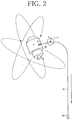
- FIG.2 is an overall schematic diagram illustrating a decelerating process of the space debris removing method according to the first embodiment of the present invention.
- FIG.3 is a flowchart illustrating the space debris removing method according to the first embodiment of the present invention.
- FIG.4 is a flowchart illustrating a modification of the space debris removing method according to the first embodiment of the present invention.
- the space debris removing method is for removing space debris undergoing an irregular tumbling motion from an orbit by capturing and decelerating the space debris as illustrated in FIG.1 to FIG.3 , and includes: an orbit injecting process (Step 1) of injecting a space debris removing device 2 around an orbit L of target debris 1 which is the space debris to be removed; an approaching process (Steps 2, 3) of making the space debris removing device 2 approach the target debris 1; an observing and moving process (Steps 4-7) of observing a motion of the target debris 1 after the space debris removing device 2 reaches an observation position T, calculating a capture position E and a capture attitude at which a harpoon 41 can be driven into the target debris 1, and moving the space debris removing device 2 to the capture position E and the capture attitude; a capturing process (Step 8) of driving the harpoon 41 into the target debris 1 and connecting the space debris removing device 2 and the target debris 1; and a decelerating process (Step 1) of injecting a space debris
- the target debris 1 is, as illustrated in FIG.1 , irregularly rotating while orbiting on the orbit L. That is, the target debris 1 is orbiting on the orbit L while undergoing an irregular tumbling motion. Therefore, when attaching a deceleration device by a robot arm, a driving timing and a driving direction of the robot arm need to be controlled so that the robot arm does not collide with the target debris 1, and calculation and control become complicated. On the other hand, in the present invention, collision of the target debris 1 and the space debris removing device 2 can be suppressed since the target debris 1 is captured by driving the harpoon 41 from the capture position E at which the space debris removing device 2 does not collide with the target debris 1.
- the orbit injecting process (Step 1) is the process of disposing the launched space debris removing device 2 around the orbit L of the target debris 1. Specifically, the space debris removing device 2 is injected into a range from which the space debris removing device 2 can reach the orbit L by itself. For instance, the space debris removing device 2 is injected to a position lower than the orbit L, and gradually approaches the orbit L by centrifugal force while approaching the target debris 1 by using a propulsion device.
- the space debris removing device 2 is in a shape of a small-sized satellite having the size of about several tens cm to several m, for instance, and may be launched alone from the earth or may be launched in the form of sharing a ride with a main satellite as a piggy bag satellite.
- the target debris 1 which is to be removed is basically set beforehand, the orbit L is measured from the earth, and the space debris removing device 2 is launched so as to be injected around the orbit L. Adjustment in orbit injection is processed by the propulsion device mounted in the space debris removing device 2 on the basis of information of GPS (Global Positioning System).
- GPS Global Positioning System
- the approaching process is the process of making the space debris removing device 2 approach the observation position T of the target debris 1.
- the observation position T is, for instance, set at a position about 30-500 m away from the target debris 1 on the orbit L.
- the space debris removing device 2 moves from an injection position S to the observation position T while recognizing a position of the device itself and a position of the target debris 1 by using the GPS or the like.
- the space debris removing device 2 checks whether or not the observation position T is reached (Step 2), approaches the target debris 1 (Step 3) when the observation position T is not reached (N), and advances to the next process when the observation position T is reached (Y).
- the observing and moving process is the process of making the space debris removing device 2 approach the capture position E of the target debris 1.
- the space debris removing device 2 which reaches the observation position T observes the target debris 1 by an observer such as a CCD camera or a laser radar (Step 4), and estimates a motion model of the target debris 1.
- the capture position E and the capture attitude for driving the harpoon 41 to the target debris 1 are calculated (Step 5).
- the capture position E is a position at which the target debris 1 undergoing the tumbling motion and the space debris removing device 2 do not collide for instance, and is set at a position about several m to several tens m away from the target debris 1.
- the capture position E may be a position off the orbit L of the target debris 1.
- the capture attitude means a state of being set to a direction from which the harpoon 41 can be driven into a part where the harpoon 41 is desired to be driven into the target debris 1.
- the space debris removing device 2 may calculate the capture position E and the capture attitude so as to drive the harpoon 41 into a hollow portion such as a tank 11 of the target debris 1.
- the capture position E and the capture attitude may be such a position and attitude that the harpoon 41 can be substantively vertically driven into the surface of the target debris 1, or may be such a position and attitude that the harpoon 41 can be driven into a position with little fluctuation such as a fixed point in the estimated motion model of the target debris 1.
- the space debris removing device 2 autonomously moves to the capture position E and the capture attitude using the propulsion device. At the time, the space debris removing device 2 checks whether or not the capture position/attitude are reached (Step 6), moves toward the capture position E and the capture attitude (Step 7) when the capture position E and the capture attitude are not reached (N), and advances to the next process when the capture position E and the capture attitude are reached(Y).
- the capturing process is the process of driving the harpoon 41 into the target debris 1 and capturing the target debris 1.
- the harpoon 41 is connected with the space debris removing device 2 by a wire 46, and when the harpoon 41 is locked to the target debris 1, the state that the target debris 1 and the space debris removing device 2 are connected by the wire 46 is attained.
- the harpoon 41 can be driven so as not to collide with the target debris 1.
- a mechanism and calculation for determining the capture position E and the capture attitude can be simplified or saved in terms of labor, a performance demanded for an observation/capture mechanism of the space debris removing device 2 can be mitigated, processing burdens on a controller can be reduced, and the target debris 1 and the space debris removing device 2 can be easily connected.
- the decelerating process (Step 9) is the process of decelerating the target debris 1 by the space debris removing device 2 and accelerating or controlling a fall to the earth.
- the decelerating process is, for instance, the process of decelerating the target debris 1 by discharging a conductive tether 61 from the space debris removing device 2 into space.
- Means for decelerating the target debris 1 may be pressure receiving means which receives a radiation pressure of the solar wind or solar light or the like.
- the conductive tether 61 may include a distal end part 62 disposed at a distal end and provided with thrust generation means for generating thrust. Since the distal end part 62 includes the thrust generation means, the conductive tether 61 can be guided into a direction in which expansion is desired, and expansion of the conductive tether 61 can be stabilized.
- the thrust generation means a small-sized rocket motor, a cold gas jet using nitrogen or liquefied alternative fluorocarbon or the like, a monopropellant, electric propulsion of a pulsed plasma thruster, and a propulsion device utilizing a sublimate such as camphor or the like can be used.
- flow from orbit injection (Step 1) to reaching the observation position T (Step 2) is carried out stepwise.
- an observer for instance, a CCD camera or a laser radar or the like
- an injection position S at which the space debris removing device 2 is injected to the orbit is often a position at least several hundreds m to several thousands m away from the target debris 1, and a moving distance to the observation position T is long.
- the space debris removing device 2 At the beginning after the space debris removing device 2 is injected to the orbit, it is preferable to use a GPS in order to recognize its own position. However, it is difficult to accurately predict the position of the target debris 1 on the basis of normal observation data from the ground, and sometimes it is difficult to accurately guide the space debris removing device 2 to the observation position T. Then, when the space debris removing device 2 approaches the target debris 1, the observation position T may be reached while monitoring the position of the target debris 1 by itself.
- the space debris removing device 2 has a monitoring device such as a laser radar mounted thereon, and the space debris removing device 2 checks whether or not a monitoring position at which the GPS is to be switched to the monitoring device is reached (Step 21), approaches the target debris 1 by using the GPS (Step 22) when the monitoring position is not reached (N), and switches from the GPS to monitoring of the target debris 1 by the monitoring device (Step 23) when the monitoring position is reached (Y). Thereafter, the space debris removing device 2 approaches while measuring a direction and a distance of the target debris 1 by the monitoring device, and advances to the next process (Step 2). Also, the processes after the Step 2 are the same as in a flowchart illustrated in FIG.3 .
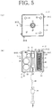
- FIG.5 is a schematic diagram illustrating the space debris removing device according to the first embodiment of the present invention, (a) illustrates a front view, and (b) illustrates a B-B cross sectional view in FIG.5(a) .
- FIG.6 is a diagram illustrating a capture device, (a) illustrates an overall diagram, (b) illustrates a perspective view of a harpoon, (c) illustrates a first modification of the harpoon, (d) illustrates a second modification of the harpoon, and (e) illustrates a third modification of the harpoon.
- FIG.7 is a diagram illustrating modifications of the harpoon, (a) illustrates a fourth modification, (b) illustrates a fifth modification, (c) illustrates a sixth modification, and (d) illustrates a seventh modification.
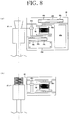
- FIG.8 is a diagram illustrating a storage state of the harpoon, (a) illustrates a schematic diagram when including a wire winding device, and (b) illustrates a schematic diagram when not including the wire winding device.
- the space debris removing device 2 is, as illustrated in FIG.5 , the space debris removing device which removes space debris undergoing an irregular tumbling motion from an orbit by capturing and decelerating the space debris, and includes: a propulsion device 3 for performing approach and attitude control to the target debris 1 (see FIG.1 ) which is the space debris to be removed; a capture device 4 having the harpoon 41 which can be ejected toward the target debris 1; an observation device 5 for observing a motion of the target debris 1 and calculating the capture position E and the capture attitude at which the harpoon 41 can be driven into a hollow portion such as the tank 11 of the target debris 1; a deceleration device 6 directly or indirectly connected to the harpoon 41, for decelerating the target debris 1; a body part 21 on which the propulsion device 3, the capture device 4, the observation device 5 and the deceleration device 6 are mounted; and a power supply device 7 charged by a solar battery panel 71 disposed on an
- the propulsion device 3 is a device used for the approach to the target debris 1 of the space debris removing device 2 (the body part 21), movement to the capture position E and the capture attitude, and attitude control of the body part 21, etc.
- the propulsion device 3 includes, for instance, a main direction thruster 31 described in FIG.5(b) , a side thruster 32 and a thruster 33 for the attitude control described in FIG.5(a) , and a propellant tank 34 for generating a gas to be jetted from the thrusters, etc.
- the configuration of the propulsion device 3 is just an example, and is not limited to the configuration illustrated in the figure.
- the capture device 4 is a device which has the harpoon 41 that can be ejected from a launcher 42 formed or installed at the body part 21 and connects the target debris 1 and the space debris removing device 2 (the body part 21).
- the harpoon 41 includes, as described in FIG.5(b) and FIGS.6(a) and (b) , a pointed end part 43 having a barb part 43a that can be locked to the target debris 1, a stopper part 44 to be in contact with the surface of the target debris 1, a thrust generation part 45 for ejecting the harpoon 41, and the wire 46 for connecting the harpoon 41 to the body part 21.
- the capture device 4 may include an ejecting direction adjusting mechanism (for instance, a gimbal mechanism or the like) for adjusting or finely adjusting an ejecting direction of the harpoon 41.
- the pointed end part 43 is constituted of a metal having strength enough to pass through the surface of the target debris 1, and has a pointed distal end.
- the barb part 43a may be constituted of a back surface of a plurality of triangular blade members formed on a side face of the pointed end part 43 or may be constituted of a conical bottom surface part.
- the stopper part 44 is for regulating the harpoon 41 so as not to pass through the target debris 1.
- the harpoon 41 passes through the front and back of the target debris 1, there is the possibility of generating extra broken pieces (debris) when the harpoon 41 gets off to the outside.
- an oxidizing agent remains when the harpoon 41 reaches an oxidizing agent tank inside the target debris 1, there is the possibility of causing an explosion.
- the harpoon 41 is driven toward the tank 11 (hollow portion) such as a fuel tank or an empty oxidizing agent tank, and the stopper part 44 is formed at the harpoon 41.
- the thrust generation part 45 is for adding thrust to the harpoon 41.
- the thrust generation part 45 is constituted of a rocket motor with solid propellant or the like, for instance.
- the launcher 42 has a hollow passing through the body part 21, and is configured such that, when the thrust generation part 45 is operated, the reaction is not easily added to the body part 21.
- the launcher 42 is not necessarily required to be built in the body part 21 and may be configured so as to be externally attached to the surface of the body part 21.
- the wire 46 is a member for connecting the harpoon 41 and the body part 21, and is the member for connecting the target debris 1 and the body part 21 (the space debris removing device 2) by the harpoon 41 locked to the target debris 1.
- the wire 46 has a length of several m to several tens m, for instance, and when the harpoon 41 is stored, is turned to the state of being wound to a wire drum 46a to suppress the fall of the harpoon 41.
- the wire 46 is delivered from the wire drum 46a accompanying the advance of the harpoon 41.
- the harpoon 41 may be locked to the launcher 42 by a shear pin or a retractable stopper to perform positioning or suppress the fall.
- the harpoon 41 illustrated in FIG.6(c) includes a cylindrical body 47 (elastic body) disposed so as to cover an outer periphery of the pointed end part 43 on a front surface of the stopper part 44, and is configured to form a closed space by compressing the cylindrical body 47 between the surface of the target debris 1 and the stopper part 44 when the pointed end part 43 is locked to the target debris 1.
- the cylindrical body 47 has a bellows structure, for instance. By disposing the cylindrical body 47, scattering of broken pieces such as heat insulating material generated when the harpoon 41 passes through can be suppressed.
- the cylindrical body 47 is configured into a substantively cylindrical shape for instance, but may be configured into a truncated conical cylindrical shape in which the diameter of a distal end side is enlarged.
- the second modification of the harpoon 41 illustrated in FIG.6(d) includes a fiber body 47' (elastic body) disposed so as to cover the pointed end part 43 on the front surface of the stopper part 44, and is configured to suppress scattering of broken pieces generated when the harpoon 41 passes through by compressing the fiber body 47' (elastic body) between the surface of the target debris 1 and the stopper part 44 when the pointed end part 43 is locked to the target debris 1.
- the fiber body 47' when the coarse one is used, the broken pieces to scatter can be entwined and caught by the fiber body 47', and when the fine one is used, the broken pieces to scatter can be held between the fiber body 47' and the surface of the target debris 1.
- the elastic body 47' Light and strong aramid fibers or the like are formed into a sponge shape for the fiber body 47', for instance, and the elastic body may be a resin like sponge or a metal such as steel wool, instead of the fiber body 47'.
- the barb part 43a of the pointed end part 43 is configured so as to be closed when passing through the target debris 1 and be opened after passing through the target debris 1.
- the barb part 43a is constituted of a leaf spring member, for instance, and is configured so as to be extended and contracted in a radial direction of the harpoon 41.
- the elastic body of rubber or a coil spring or the like may be disposed.
- an opening/closing mechanism of the barb part 43a is just an example, and is not limited to the configuration illustrated in the figure.
- the plurality of pointed end parts 43 are disposed on the surface of the stopper part 44. While one pointed end part 43 is disposed in the harpoon 41 illustrated in FIG.6(b) , three pointed end parts 43 are disposed in the harpoon 41 illustrated in FIG.7(a) . Also, on an outer periphery of the pointed end parts 43, the cylindrical body 47 may be disposed as illustrated in the figure.
- the harpoon 41 illustrated in FIGS.7(b)-(d) assume the case that, in the harpoon 41 including the plurality of pointed end parts 43, a part of the harpoon 41 is driven into a hard part (for instance, a part where a rib 12 configuring a reinforcing part of the target debris 1 is formed) of the target debris 1.
- the respective pointed end parts 43 are configured so as to be capable of being pulled in when the surface of the target debris 1 cannot be passed through.
- the pointed end part 43 is fixed to the stopper part 44 by a shear pin 43b to be broken when a fixed pressure is loaded.
- a space (a storage part 44a) capable of storing the pointed end part 43 including the barb part 43a is formed. Shear force of the shear pin 43b is adjusted so as not to be broken when the pointed end part 43 collides with a plate part of the target debris 1 and so as to be broken when the pointed end part 43 collides with the hard part of the target debris 1.
- the respective pointed end parts 43 are configured to be capable of being pulled in by a gas cylinder 44b.
- the respective pointed end parts 43 are supported through a piston 43c inserted into the gas cylinder 44b.
- the pointed end parts 43 can be pulled in by utilizing compressibility of a gas.
- the gas cylinder 44b by configuring the gas cylinder 44b so as to communicate cylinder parts corresponding to the respective pointed end parts 43, by the gas compressed by a certain pointed end part 43, the other pointed end part 43 can be energized to the front.
- the gas cylinder 44b may be disposed individually for the respective pointed end parts 43.
- the respective pointed end parts 43 are configured to be capable of being pulled in by a coil spring 43d.
- Elastic force of the coil spring 43d is adjusted so as not to be compressed when the pointed end part 43 collides with a plate part of the target debris 1 and so as to be compressed when the pointed end part 43 collides with the hard part of the target debris 1.
- the elastic body of rubber or the like may be used.
- the observation device 5 includes, for instance, an observer 51 disposed at a front part of the body part 21, and an operation part 52 for detecting the relative position and attitude of the target debris 1 and the body part 21 from video images or images or the like obtained by the observer 51, estimating the motion model of the target debris 1 from time series information of the position and the attitude, and calculating the capture position E and the capture attitude.
- the observer 51 is constituted of a CCD camera or a laser radar or the like capable of acquiring the tumbling motion of the target debris 1 as the video image or the image or the like.
- the operation part 52 is constituted of an arithmetic processing unit such as a CPU, and may include a storage device for recording the video images or the images or the like of the observer 51.
- the operation part 52 may be constituted of a part of a controller (not shown in the figure) of the space debris removing device 2.
- the controller operates the propulsion device 3 on the basis of an operation result of the observation device 5, makes the body part 21 be moved to the capture position E, and adjusts an ejecting direction (capture attitude) of the harpoon 41.
- the capture device 4 includes the ejecting direction adjusting mechanism, rough positioning and attitude determination may be performed in the propulsion device 3 and the ejecting direction of the harpoon 41 may be finely adjusted in the ejecting direction adjusting mechanism.
- the deceleration device 6 includes, for instance, the conductive tether 61 to be discharged into space, and the distal end part 62 disposed at the distal end of the conductive tether 61 and provided with the thrust generation means for generating thrust.
- the thrust generation means a small-sized rocket motor, a cold gas jet, a one-liquid thruster, electric propulsion, and a sublimate or the like can be utilized.
- the conductive tether 61 is, as illustrated in the figure, stored inside a case in a coil shape, and is configured so as to be loosened into a straight shape by discharging the distal end part 62.
- the deceleration device 6 may be stored inside the body part 21 or may be attached externally to the surface of the body part 21.
- the power supply device 7 includes, for instance, the solar battery panel 71 disposed on the outer surface of the body part 21, and a battery 72 for storing electricity generated by the solar battery panel 71.
- the electricity charged to the battery 72 supplies power to devices requiring the power such as the propulsion device 3, the capture device 4, the observation device 5 and the deceleration device 6 as needed through the controller.
- the body part 21 is constituted of a housing similar to a so-called small-sized satellite.
- the body part 21 may have a monitoring device 22 such as a laser radar, a GPS sensor, a gyro, and an acceleration sensor or the like mounted thereon.
- the outer periphery of the body part 21 is covered with a heat insulating material.
- the capture device 4 may include a wire winding device 48 capable of winding the wire 46, as illustrated in FIG.8(a) .
- the wire winding device 48 includes, for instance, an electric motor 48a for generating motive power, a belt driving mechanism (a timing belt 48b and a pulley 48c) for transmitting the motive power of the electric motor 48a to a wire drum 46a, a control part 48d for controlling the motive power of the electric motor 48a, and a level winding mechanism 48e for uniformly winding the wire 46.
- a power transmission mechanism is not limited to the belt driving mechanism, and may be constituted of a gear train.
- the body part 21 can be closely fitted to the target debris 1 by winding the wire 46 after locking the pointed end part 43 to the target debris 1. Also, since there is the possibility that the wire 46 is entangled with the target debris 1 if the wire 46 is loosened between the target debris 1 and the space debris removing device 2, the wire winding device 48 may be operated so as to load the wire 46 with fixed tension and maintain a straight tense state.
- the wire winding device 48 When winding of the wire 46 is not needed, as illustrated in FIG.8(b) , the wire winding device 48 may be omitted. In order to stabilize rewinding of the wire 46 from the wire drum 46a, the level winding mechanism 48e may be disposed. Also, the wire 46 may be not only wound around the wire drum 46a but also wound around a rear end part of the harpoon 41. Further, when the length of the wire 46 is short, the wire drum 46a may be omitted. When winding the wire 46 around the rear end part of the harpoon 41, it is preferable to wind the wire 46 from the front to the back for instance so that the wire 46 is smoothly loosened when ejecting the harpoon 41.
- FIG.9 is a schematic diagram illustrating the space debris removing device according to a second embodiment of the present invention, (a) illustrates a front view, (b) illustrates a B-B cross sectional view in FIG.9(a), and (c) illustrates a schematic diagram illustrating a using state.
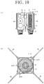
- FIG.10 is a schematic diagram illustrating the space debris removing device according to a third embodiment of the present invention, (a) illustrates a cross sectional view, and (b) illustrates a front view.
- FIG.11 is a schematic diagram illustrating binding legs, (a) illustrates a first example, (b) illustrates a second example, and (c) illustrates a third example.
- the same signs are attached to the same components as the space debris removing device 2 according to the first embodiment and redundant descriptions will be omitted.
- an annular buffer material 23 is disposed at the front part of the body part 21.
- the buffer material 23 is formed of a metal such as an aluminum honeycomb or a resin such as urethane rubber.
- the space debris removing device 2 can be closely fitted to the target debris 1 even when a surface shape of the target debris 1 is a complicated shape, strict position/speed control is not required when closely fitting the space debris removing device 2 to the target debris 1 undergoing the tumbling motion, position/speed control loads when performing close fitting can be mitigated, a mechanism and calculation for determining a position/attitude/speed for performing close fitting can be simplified or saved in terms of labor, the performance demanded for an observation/capture mechanism of the space debris removing device 2 can be mitigated, the processing burdens on the controller can be reduced, and the target debris 1 and the space debris removing device 2 can be easily connected.
- the configuration of the buffer material 23 is not limited to the one illustrated in the figure, and may be a rectangular ring shape or the configuration of being distributed and disposed at the front part of the body part 21.
- the space debris removing device 2 includes a plurality of binding legs 24 turnably disposed at the body part 21, and after the body part 21 is closely fitted to the target debris 1, the binding legs 24 are expanded to fix the body part 21 to the target debris 1, and the motion of the target debris 1 is suppressed using the propulsion device 3.
- the state of closing the binding legs 24 is illustrated in FIG.10(a)
- the state of opening the binding legs 24 is illustrated in FIG.10(b) .
- the irregular tumbling motion of the target debris 1 can be suppressed by the binding legs 24 and the propulsion device 3, and the deceleration device can be used in a stable state.
- the conductive tether 61 is used as the deceleration device 6, the conductive tether 61 can be prevented from moving wildly or getting entangled.
- the space debris removing device 2 can be bound to the target debris 1 even when the surface shape of the target debris 1 is a complicated shape, and since the degree of freedom of a position to be connected to the target debris 1 undergoing the tumbling motion (that is, a harpoon driving position) is increased, a mechanism and calculation for determining the capture position E and the capture attitude can be simplified or saved in terms of labor, the performance demanded for an observation/capture mechanism of the space debris removing device 2 can be mitigated, the processing burdens on the controller can be reduced, and the target debris 1 and the space debris removing device 2 can be easily connected.
- FIG.10(b) figures of the side thruster 32 and the thruster 33 for the attitude control are omitted for convenience of descriptions.
- the binding legs 24 have a configuration illustrated in FIGS.11(a)-(c) for instance.
- the figure of the buffer material 23 is omitted.
- the configurations of the first example to the third example of the binding legs 24 are just examples, and not limited to the configurations.
- the binding leg 24 is turned by an electric motor 24a.
- the electric motor 24a has a brake function, and is configured to hold the binding leg 24 in a stored state and an expanded state.
- a sensor 24b may be disposed at the body part 21 and the distal end of the binding leg 24 to sense the contact of the body part 21 and the target debris 1, thereby operating the electric motor 24a and expanding the binding leg 24, and to sense the contact of the binding leg 24 and the target debris 1, thereby stopping the electric motor 24a and locking the binding leg 24.
- force may be continuously applied to the binding leg 24 by the electric motor 24a to fix the body part 21 to the target debris 1.
- the binding leg 24 is turned by a cylinder 24c.
- the cylinder 24c is pin-connected to the binding leg 24 at a distal end and pin-connected to the body part 21 at a rear end.
- the cylinder 24c is a hydraulic cylinder, an air cylinder or an electric cylinder or the like for instance, and is configured so as to be extended and contracted.
- the sensor 24b may be disposed at the body part 21 and the distal end of the binding leg 24 to sense the contact of the body part 21 and the target debris 1, thereby extending the cylinder 24c and expanding the binding leg 24, and to sense the contact of the binding leg 24 and the target debris 1, thereby stopping the extension of the cylinder 24c and locking the binding leg 24.
- force may be continuously applied to the binding leg 24 by the cylinder 24c to fix the body part 21 to the target debris 1.
- the binding leg 24 is turned by a coil spring 24d.
- the coil spring 24d is stored inside a container in the state of being compressed to energize a drive shaft 24e pin-connected to the binding leg 24 at the distal end, and a closed state is kept by a stopper 24f connected to the body part 21 through a latch mechanism.
- the stopper 24f is turned upwards, and the binding leg 24 is expanded.
- force is continuously applied to the binding leg 24 by the coil spring 24d.
- a locking part for instance, a harpoon shape
- an adhesion part to be bonded or fixed to the surface of the body part 21 by applying or discharging an adhesive agent may be formed at the distal end of the binding leg 24.
- the binding leg 24 is not limited to the configuration of a turning type, and may be the configuration of a fixing type formed so as to be brought into contact from the body part 21 toward the target debris 1 or may have the locking part or the adhesion part formed at the distal end thereof, or the turning type and the fixing type may be used together.
- FIG.12 is a flowchart illustrating a part of the space debris removing method according to the third embodiment of the present invention.
- FIG.13 is an overall schematic diagram illustrating the decelerating process of the space debris removing method according to the third embodiment of the present invention.
- the flowchart illustrated in FIG.12 illustrates the capturing process (Step 8) in detail.
- the space debris removing device 2 launches the harpoon 41 toward the target debris 1 (Step 82).
- the space debris removing device 2 checks whether or not the harpoon 41 is pierced to the target debris 1 (Step 83). Whether or not the harpoon 41 is pierced may be visually checked by the observer 51 of the observation device 5 or may be checked by the tension of the wire 46.
- Step 84 When the harpoon 41 is not pierced (N), whether or not there is a spare harpoon 41 is checked (Step 84). When there is no spare harpoon 41 (N), processing is ended due to a capture failure. When there is a spare harpoon 41 (Y), the harpoon 41 is launched again (Step 82).
- the wire 46 is wound by the wire winding device 48 (Step 85), and the space debris removing device 2 (the body part 21) is closely fitted to the target debris 1 (Step 86). Thereafter, the space debris removing device 2 expands the binding legs 24 (Step 87) and binds the target debris 1. Then, by appropriately jetting the main direction thruster 31, the side thruster 32 and the thruster 33 for the attitude control of the propulsion device 3, the motion of the target debris 1 is suppressed (Step 88). After the tumbling motion of the target debris 1 is calmed down, the process is shifted to the decelerating process (Step 9).
- the process may be stopped at a closely fitting process (Step 86) of closely fitting the space debris removing device 2 to the target debris 1 by winding the wire 46 connected to the harpoon 41 after driving the harpoon 41 into the target debris 1. Also, after checking that the harpoon 41 is pierced to the target debris 1 (Steps 83-84), the subsequent processes (Steps 85-88) may be omitted to shift to the decelerating process (Step 9).
- Steps 85-88 since the need of the process of closely fitting the space debris removing device 2 to the target debris 1 undergoing the tumbling motion is eliminated, position/speed control when performing close fitting can be omitted, the mechanism and calculation for determining the position/attitude/speed of the space debris removing device 2 can be simplified or saved in terms of labor, the performance demanded for an observation/capture mechanism of the space debris removing device 2 can be mitigated, and the processing burdens on the controller can be reduced.
- FIG.13 illustrates the state of discharging the conductive tether 61 in the decelerating process (Step 9) after suppressing the motion of the target debris 1 by the capturing process (Steps 81-88).
- the conductive tether 61 discharged into space is prevented from moving wildly or getting entangled, and a deceleration effect can be stably actuated.
- FIG.14 is a schematic diagram illustrating the space debris removing device according to a fourth embodiment of the present invention, (a) illustrates a rear view, (b) illustrates a B-B cross sectional view in FIG.14(a), and (c) illustrates a schematic diagram illustrating the using state.
- FIG.15 is a schematic diagram illustrating the space debris removing device according to a fifth embodiment of the present invention, (a) illustrates a rear view, (b) illustrates a B-B cross sectional view in FIG.15(a), and (c) illustrates a schematic diagram illustrating the using state.
- FIG.16 is a schematic diagram illustrating the space debris removing device according to a sixth embodiment of the present invention, (a) illustrates a rear view, (b) illustrates a B-B cross sectional view in FIG.16(a), and (c) illustrates a schematic diagram illustrating the using state.
- the same signs are attached to the same components as the space debris removing device 2 according to the first to third embodiments and redundant descriptions will be omitted.
- the deceleration device 6 is externally attached to the surface (back surface part) of the body part 21.
- the deceleration device 6 By disposing the deceleration device 6 outside the body part 21, a free space can be secured inside the body part 21, and the plurality of harpoons 41 can be mounted by utilizing the free space. That is, the plurality of capture devices 4 may be disposed in the body part 21.
- the capture devices 4 may be disposed at four parts on diagonal lines as illustrated in FIG.14(a) , may be disposed at two parts on one diagonal line, may be disposed at three parts configuring vertexes of a triangle, or may be disposed at two parts in parallel.
- the capture devices 4 (harpoons 41) be redundant in such a manner, even when the first harpoon 41 is not pierced to the target debris 1, the harpoon 41 can be ejected again to capture the target debris 1, and redundancy of a capture function can be improved.
- the propulsion device 3 (the main direction thruster 31, the side thruster 32, the thruster 33 for the attitude control) is used to change a direction of the body part 21, the deceleration device 6 is discharged from the body part 21, and the conductive tether 61 is expanded in space.
- the deceleration device 6 configures the distal end part 62 which is a storage part of the conductive tether 61 and also has propulsion power.
- the conductive tether 61 can be expanded into a desired state.
- the deceleration device 6 is externally attached to the surface of the body part 21, and the body part 21 is utilized as the distal end part 62 of the deceleration device 6.
- the wire 46 of the capture device 4 is connected with a rear end of the conductive tether 61 through a connector 63, and the conductive tether 61 and the connector 63 may be accommodated inside the deceleration device 6 fixed to the back surface part of the body part 21.
- the space debris removing device 2 has the connector 63 for connecting the conductive tether 61 and the wire 46, and the distal end part 62 is constituted of the body part 21.
- the wire 46 may be extended to the deceleration device 6 at the back surface part along an outer edge part of the body part 21.
- the connector 63 is constituted of an electrical insulator so that static electricity or the like generated by the contact of the harpoon 41 and the target debris 1 is not transmitted to the conductive tether 61.
- the plurality of capture devices 4 may be disposed in the body part 21 similarly to the fourth embodiment.
- the propulsion device 3 (the main direction thruster 31, the side thruster 32, the thruster 33 for the attitude control) is used to change a direction of the body part 21, the body part 21 is moved in a direction in which the conductive tether 61 is desired to be expanded (for instance, a direction toward the earth) as needed while discharging the connector 63 and the conductive tether 61 from the deceleration device 6 or the body part 21, and the deceleration device 6 is separated and cut off from the body part 21.
- attitude controllable thrust generation means may be mounted in the deceleration device 6 to change the direction or the like by itself after separating the deceleration device 6 from the body part 21.
- the conductive tether 61 may be expanded into the desired state by moving the body part 21 in the direction in which the conductive tether 61 is desired to be expanded (for instance, the direction toward the earth) while discharging the connector 63 and the conductive tether 61 from the deceleration device 6 or the body part 21.
- the body part 21 can be used as the distal end part 62 of the deceleration device 6, and the configuration of the deceleration device 6 can be simplified.
- the deceleration device 6 is externally attached to the surface of the body part 21, the body part 21 is utilized as the distal end part 62 of the deceleration device 6, and a part of the deceleration device 6 is configured so as to be separated from the body part 21.
- the deceleration device 6 illustrated in the fifth embodiment is divided into a plurality of devices that are a first deceleration device 6a, a second deceleration device 6b, a third deceleration device 6c and a fourth deceleration device 6d, and the first deceleration device 6a to the fourth deceleration device 6d are configured so as to be separated (cut off) from the body part 21 individually. It is preferable that a division number of the deceleration device 6 is set so as to be in one-to-one correspondence with the capture devices 4 (harpoons 41).
- the propulsion device 3 (the main direction thruster 31, the side thruster 32, the thruster 33 for the attitude control) is used to change the direction of the body part 21, the body part 21 is moved in a direction in which the conductive tether 61 is desired to be expanded (for instance, the direction toward the earth) as needed while discharging the connector 63 and the conductive tether 61 from the deceleration device 6 (for instance, the first deceleration device 6a), and the first deceleration device 6a is separated and cut off from the body part 21.
- attitude controllable thrust generation means may be mounted in the first deceleration device 6a to change the direction or the like by itself after separating the first deceleration device 6a from the body part 21.
- the space debris removing device 2 moves toward the next target debris 1 by using the propulsion device 3.
- the space debris removing device 2 may be moved toward the next target debris 1 by separating and cutting off the first deceleration device 6a from the body part 21 after the conductive tether 61 is expanded by the space debris removing device 2.
Landscapes
- Engineering & Computer Science (AREA)
- Remote Sensing (AREA)
- Aviation & Aerospace Engineering (AREA)
- General Physics & Mathematics (AREA)
- Astronomy & Astrophysics (AREA)
- Physics & Mathematics (AREA)
- Radar, Positioning & Navigation (AREA)
- Combustion & Propulsion (AREA)
- Chemical & Material Sciences (AREA)
- Life Sciences & Earth Sciences (AREA)
- Geology (AREA)
- Geochemistry & Mineralogy (AREA)
- General Life Sciences & Earth Sciences (AREA)
- Environmental & Geological Engineering (AREA)
- Cleaning In General (AREA)
- Manipulator (AREA)
Claims (15)
- Eine Weltraumschrott-Beseitigungsvorrichtung (2) zum Beseitigen von einer unregelmäßigen Taumelbewegung ausgesetztem Weltraumschrott aus einer Umlaufbahn durch Einfangen und Abbremsen des Weltraumschrotts, umfassend:eine Antriebsvorrichtung (3) zum Durchführen einer Annäherungs- und Lagekontrolle in Bezug auf Zielschrott (1), bei dem es sich um den zu beseitigenden Weltraumschrott handelt;eine Einfangvorrichtung (4) mit einer Harpune (41), die in Richtung zum Zielschrott (1) abgefeuert werden kann;eine Beobachtungsvorrichtung (5) zum Beobachten einer Bewegung des Zielschrotts (1) und zum Berechnen einer Einfangposition (E) und einer Einfanglage, bei der die Harpune (41) in einen Abschnitt des Zielschrotts (1) getrieben werden kann;eine Abbremsvorrichtung (6), die direkt oder indirekt mit der Harpune (41) verbunden ist, zum Abbremsen des Zielschrotts (1); undein Körperteil (21), an dem die Antriebsvorrichtung (3), die Einfangvorrichtung (4), die Beobachtungsvorrichtung (5) und die Abbremsvorrichtung (6) montiert sind,wobei der Abschnitt des Zielschrotts (1), in den die Harpune (41) getrieben werden kann, hohl ist; dadurch gekennzeichnet, dassdie Harpune (41) ein spitzes Endteil (43) mit einem Widerhakenteil (43a), das sich am Zielschrott (1) verhaken kann, ein Stopperteil (44), das mit einer Oberfläche des Zielschrotts (1) in Kontakt geraten soll, ein Schuberzeugungsteil (45) zum Abfeuern der Harpune (41) und einen Draht (46) zum Verbinden der Harpune (41) mit dem Körperteil (21) aufweist, unddie Harpune (41) einen elastischen Körper (47, 47') aufweist, der so angeordnet ist, dass er das spitze Endteil (43) an einer Vorderfläche des Stopperteils (44) bedeckt, und durch Zusammendrücken des elastischen Körpers (47, 47') zwischen der Oberfläche des Zielschrotts (1) und dem Stopperteil (44), wenn das spitze Endteil (43) an dem Zielschrott (1) verhakt ist, ein Streuen von Bruchstücken, die beim Durchtritt der Harpune (41) erzeugt werden, unterbunden wird.
- Weltraumschrott-Beseitigungsvorrichtung (2) gemäß Anspruch 1, wobei das Widerhakenteil (43a) so konfiguriert ist, dass es beim Hindurchgehen durch den Zielschrott (1) geschlossen ist und nach Hindurchgehen durch den Zielschrott (1) geöffnet wird.
- Weltraumschrott-Beseitigungsvorrichtung (2) gemäß Anspruch 1, wobei eine Vielzahl der spitzen Endteile (43) an einer Oberfläche des Stopperteils (44) angeordnet ist und jedes der spitzen Endteile (43) so konfiguriert ist, dass es eingezogen werden kann, wenn es an einer Stelle anliegt, an der das spitze Endteil (43) nicht durch die Oberfläche des Zielschrotts (1) hindurchgehen kann.
- Weltraumschrott-Beseitigungsvorrichtung (2) gemäß Anspruch 1, wobei eine Drahtwickelvorrichtung (48) vorgesehen ist, die in der Lage ist, den Draht (46) aufzuwickeln, und durch Aufwickeln des Drahtes (46) nach dem Verhaken des spitzen Endteils (43) am Zielschrott (1) das Körperteil (21) eng an den Zielschrott (1) angelegt werden kann.
- Weltraumschrott-Beseitigungsvorrichtung (2) gemäß Anspruch 4, wobei ein Puffermaterial (23) zum Abschwächen eines Aufpralls beim engen Anlegen des Körperteils (21) am Zielschrott (1) am Körperteil (21) angeordnet ist.
- Weltraumschrott-Beseitigungsvorrichtung (2) gemäß Anspruch 4, wobei eine Vielzahl von Bindungsschenkeln (24) vorgesehen ist, welche drehbar am Körperteil (21) angeordnet sind, und nachdem das Körperteil (21) eng an den Zielschrott (1) angelegt ist, die Bindungsschenkel (24) ausgefahren werden, um das Körperteil (21) am Zielschrott (1) zu befestigen, und die Bewegung des Zielschrotts (1) unter Verwendung der Antriebsvorrichtung (3) unterbunden wird.
- Weltraumschrott-Beseitigungsvorrichtung (2) gemäß Anspruch 1, wobei eine Vielzahl von Einfangvorrichtungen (4) am Körperteil (21) angeordnet ist.
- Weltraumschrott-Beseitigungsvorrichtung (2) gemäß Anspruch 1, wobei die Abbremsvorrichtung (6) eine leitende Leine (61), die in den Weltraum ausgebracht wird, und ein distales Endteil (62) aufweist, das an einem distalen Ende der leitenden Leine (61) angeordnet und mit Schuberzeugungsmitteln zum Erzeugen von Schub ausgestattet ist.
- Weltraumschrott-Beseitigungsvorrichtung (2) gemäß Anspruch 1, wobei die Abbremsvorrichtung (6) eine leitende Leine (61), die in den Weltraum ausgebracht wird, ein distales Endteil (62), das an einem distalen Ende der leitenden Leine (61) angeordnet und mit Schuberzeugungsmitteln zur Erzeugung von Schub versehen ist, und ein Verbindungsstück (63) zum Verbinden eines hinteren Endes der leitenden Leine (61) mit dem Draht (46) aufweist, und der Draht (46) mit dem Körperteil (21) über die leitende Leine (61) und den distalen Endabschnitt (62) verbunden ist.
- Weltraumschrott-Beseitigungsvorrichtung (2) gemäß Anspruch 8 oder Anspruch 9, wobei die leitende Leine (61) so verbunden ist, dass sie sich von dem Körperteil (21) trennen lässt.
- Weltraumschrott-Beseitigungsvorrichtung (2) gemäß Anspruch 8 oder Anspruch 9, wobei das distale Endteil (62) durch das Körperteil (21) konfiguriert ist.
- Ein Weltraumschrott-Beseitigungsverfahren, das Weltraumschrott, der einer unregelmäßigen Taumelbewegung ausgesetzt ist, aus einer Umlaufbahn durch Einfangen und Abbremsen des Weltraumschrotts beseitigt, umfassend:ein Umlaufbahn-Einschießvorgang zum Einschießen einer Weltraumschrott-Beseitigungsvorrichtung (2) in eine Umlaufbahn (L) von Zielschrott (1), bei dem es sich um den zu beseitigenden Weltraumschrott handelt;einen Annäherungsvorgang, bei dem die Weltraumschrott-Beseitigungsvorrichtung (2) an den Zielschrott (1) angenähert wird;einen Beobachtungs- und Bewegungsvorgang zum Beobachten einer Bewegung des Zielschrotts (1), nachdem die Weltraumschrott-Beseitigungsvorrichtung (2) eine Beobachtungsposition (T) erreicht hat, Berechnen einer Einfangposition (E) und einer Einfanglage, bei der eine Harpune (41) in den Zielschrott (1) getrieben werden kann, und Bewegen der Weltraumschrott-Beseitigungsvorrichtung (2) in die Einfangposition (E) und die Einfanglage;einen Einfangvorgang, bei dem die Harpune (41) in den Zielschrott (1) getrieben wird und die Weltraumschrott-Beseitigungsvorrichtung (2) und der Zielschrott (1) verbunden werden; undeinen Abbremsvorgang, bei dem der Zielschrott (1) durch die Weltraumschrott-Beseitigungsvorrichtung (2) abgebremst wird,wobei der Beobachtungs- und Bewegungsvorgang die Einfangposition (E) und die Einfanglage berechnet, um die Harpune (41) in einen hohlen Abschnitt des Zielschrotts (1) zu treiben,
dadurch gekennzeichnet, dassdie Harpune (41) ein spitzes Endteil (43) mit einem Widerhakenteil (43a), das an dem Zielschrott (1) verhakt werden kann, ein Stopperteil (44), das mit einer Oberfläche des Zielschrotts (1) in Kontakt gelangen soll, ein Schuberzeugungsteil (45) zum Abfeuern der Harpune (41) und einen Draht (46) zum Verbinden der Harpune (41) mit der Weltraumschrott-Beseitigungsvorrichtung (2) aufweist, unddie Harpune (41) einen elastischen Körper (47, 47') aufweist, der so angeordnet ist, dass er das spitze Endteil (43) an einer Vorderfläche des Stopperteils (44) bedeckt, und durch Zusammendrücken des elastischen Körpers (47, 47') zwischen der Oberfläche des Zielschrotts (1) und dem Stopperteil (44), wenn das spitze Endteil (43) an dem Zielschrott (1) verhakt ist, ein Streuen von Bruchstücken, die beim Durchtritt der Harpune (41) erzeugt werden, unterbunden wird. - Weltraumschrott-Beseitigungsverfahren gemäß Anspruch 12, wobei der Einfangvorgang einen von einem engen Anlegen begleiteten Vorgang des Aufwickelns eines mit der Harpune (41) verbundenen Drahts (46) beinhaltet, nachdem die Harpune (41) in den Zielschrott (1) getrieben wurde, und die Weltraumschrott-Beseitigungsvorrichtung (2) eng an den Zielschrott (1) angelegt wird.
- Weltraumschrott-Beseitigungsverfahren gemäß Anspruch 13, wobei der Einfangvorgang einen Bindungsvorgang aufweist, bei dem Bindungsschenkel (24), die an der Weltraumschrott-Beseitigungsvorrichtung (2) angeordnet sind, ausgefahren werden, und der Zielschrott (1) gebunden wird, nachdem die Weltraumschrott-Beseitigungsvorrichtung (2) eng an den Zielschrott (1) angelegt wurde, und einen Bewegungsunterbindungsvorgang zum Unterbinden einer Bewegung des Zielschrotts (1) durch eine an der Weltraumschrott-Beseitigungsvorrichtung (2) angeordnete Antriebsvorrichtung (3).
- Weltraumschrott-Beseitigungsverfahren gemäß Anspruch 12, wobei es sich bei dem Abbremsvorgang um einen Vorgang zum Abbremsen des Zielschrotts (1) durch Ausbringen einer leitenden Leine (61) aus der Weltraumschrott-Beseitigungsvorrichtung (2) in den Weltraum handelt.
Applications Claiming Priority (2)
| Application Number | Priority Date | Filing Date | Title |
|---|---|---|---|
| JP2011241170 | 2011-11-02 | ||
| PCT/JP2012/078359 WO2013065795A1 (ja) | 2011-11-02 | 2012-11-01 | スペースデブリ除去装置及びスペースデブリ除去方法 |
Publications (3)
| Publication Number | Publication Date |
|---|---|
| EP2774855A1 EP2774855A1 (de) | 2014-09-10 |
| EP2774855A4 EP2774855A4 (de) | 2015-08-12 |
| EP2774855B1 true EP2774855B1 (de) | 2020-01-08 |
Family
ID=48192133
Family Applications (1)
| Application Number | Title | Priority Date | Filing Date |
|---|---|---|---|
| EP12844873.5A Active EP2774855B1 (de) | 2011-11-02 | 2012-11-01 | Vorrichtung zum entfernen von weltraumschrott und verfahren zum entfernen von weltraumschrott |
Country Status (5)
| Country | Link |
|---|---|
| US (1) | US9463884B2 (de) |
| EP (1) | EP2774855B1 (de) |
| JP (1) | JP5781623B2 (de) |
| CA (1) | CA2853892C (de) |
| WO (1) | WO2013065795A1 (de) |
Families Citing this family (56)
| Publication number | Priority date | Publication date | Assignee | Title |
|---|---|---|---|---|
| ES2484845T3 (es) * | 2012-06-07 | 2014-08-12 | Astrium Limited | Captura de objetos espaciales |
| JP6051101B2 (ja) * | 2013-05-20 | 2016-12-27 | 川崎重工業株式会社 | 伸展バネを用いたスペースデブリ除去デバイス固定装置、並びに、これを備えるスペースデブリ除去デバイス |
| JP6245549B2 (ja) * | 2013-05-20 | 2017-12-13 | 国立研究開発法人宇宙航空研究開発機構 | デバイス固定装置およびこれを備えるデバイス |
| WO2015053063A1 (ja) * | 2013-10-07 | 2015-04-16 | アストロスケール プライベート リミテッド | 回転抑制装置 |
| EP2860115A1 (de) * | 2013-10-11 | 2015-04-15 | Thales Alenia Space Deutschland GmbH | Verfahren zur Modifikation von unkontrollierten Objekten im Weltraum und Raumfahrzeug zur Durchführung des Verfahrens |
| JP6472600B2 (ja) | 2014-03-18 | 2019-02-20 | 株式会社アストロスケール | 宇宙用装置、デブリ除去システム及びデブリ除去方法 |
| JP6473960B2 (ja) * | 2014-06-13 | 2019-02-27 | 国立研究開発法人宇宙航空研究開発機構 | スペースデブリの軌道降下方法、軌道降下システム、及び、人工衛星の軌道変換方法、軌道変換システム |
| JP6429109B2 (ja) * | 2014-09-30 | 2018-11-28 | 株式会社Ihi | デブリ除去装置及びデブリ除去方法 |
| JPWO2016063923A1 (ja) * | 2014-10-24 | 2017-09-21 | 株式会社アストロスケール | 非協力接近に関する誘導方法 |
| EP3015369B1 (de) * | 2014-10-30 | 2019-04-17 | Airbus Defence and Space Limited | Abfangen von Weltraummüll |
| FR3029615B1 (fr) * | 2014-12-05 | 2018-01-05 | Thales | Dispositif de lancement d'un projectile par fluide comprime |
| JP6525595B2 (ja) * | 2015-01-09 | 2019-06-05 | キヤノン電子株式会社 | 宇宙浮遊物捕捉装置 |
| FR3038297B1 (fr) * | 2015-07-01 | 2017-07-21 | Thales Sa | Systeme spatial pour reduire les vitesses angulaires d'un debris avant de le desorbiter |
| AT517928A2 (de) * | 2015-11-06 | 2017-05-15 | Keba Ag | Steuerungssystem für elektrisch gesteuerte Anlagen |
| RU2626788C2 (ru) * | 2015-12-23 | 2017-08-01 | Федеральное государственное бюджетное образовательное учреждение высшего образования Московский авиационный институт (национальный исследовательский университет) (МАИ) | Спускаемый аппарат-буксир для снятия космических объектов с орбиты |
| JP6472772B2 (ja) * | 2016-05-30 | 2019-02-20 | 株式会社アストロスケール | 対象物の除去方法、運搬方法及び制御方法 |
| CN106467178B (zh) * | 2016-09-19 | 2018-11-02 | 哈尔滨工业大学 | 触须粘附式大尺寸空间非合作目标快速消旋处理包 |
| US9714101B1 (en) * | 2016-10-25 | 2017-07-25 | Marshall H. Kaplan | Apparatus and methods for orbital debris removal |
| FR3058393A1 (fr) * | 2016-11-10 | 2018-05-11 | Airbus Defence And Space Sas | Engin spatial comprenant des moyens de controle actif d’attitude et des moyens de controle passif d’attitude |
| KR101815922B1 (ko) | 2016-11-21 | 2018-01-08 | 안세환 | 우주 쓰레기의 전자기적 처리를 위한 우주쓰레기 처리 시스템 |
| RU2661378C1 (ru) * | 2016-12-09 | 2018-07-16 | Акционерное общество "Корпорация космических систем специального назначения "Комета" | Способ очистки околоземного космического пространства от крупногабаритных объектов космического мусора |
| JP2018114932A (ja) | 2017-01-20 | 2018-07-26 | 株式会社Ihi | スペースデブリ捕獲装置及びスペースデブリ除去装置 |
| US20180222604A1 (en) * | 2017-02-09 | 2018-08-09 | Thales | Satellite propelled by laser ablation |
| US11724824B2 (en) * | 2017-06-19 | 2023-08-15 | EnergeticX.net, L.L.C. | Systems and techniques for launching a payload |
| CN109421942A (zh) * | 2017-08-27 | 2019-03-05 | 南京乐朋电子科技有限公司 | 旋转伸缩式太空垃圾回收飞船 |
| US10059470B1 (en) | 2018-02-09 | 2018-08-28 | Launchspace Technologies Corporation | Apparatus and methods for creating artificial geosynchronous orbits |
| US10543939B2 (en) | 2018-02-09 | 2020-01-28 | Launchspace Technologies Corporation | Apparatus and methods for creating artificial near-earth orbits |
| CN112512924B (zh) * | 2018-04-30 | 2022-08-16 | J·弗朗西斯三世·达金 | 从近地轨道清除轨道太空碎片 |
| WO2020031266A1 (ja) * | 2018-08-07 | 2020-02-13 | 株式会社日本製鋼所 | 物体の軌道変更システム及び物体の軌道変更方法 |
| CN109693810B (zh) * | 2018-12-29 | 2022-04-26 | 西北工业大学 | 一种用于空间碎片清理的纳星结构 |
| US20210031949A1 (en) * | 2019-07-10 | 2021-02-04 | MolyWorks Materials Corporation | Low Earth Orbit Neutral Impulse Defense And Salvage (LEONIDAS) Launch System And Method Of Fabrication |
| CN110435935B (zh) * | 2019-07-23 | 2023-01-24 | 哈尔滨工业大学 | 一种可重复穿透和固定碎片的飞锚 |
| EA038352B1 (ru) * | 2019-07-26 | 2021-08-12 | Федеральное государственное бюджетное образовательное учреждение высшего образования "Омский государственный технический университет" | Способ увода объектов крупногабаритного космического мусора и устройство для его реализации |
| CN110979745B (zh) * | 2019-11-08 | 2021-09-07 | 北京卫星制造厂有限公司 | 一种基于洛伦兹力的空间防护方法及系统 |
| RU2726338C1 (ru) * | 2019-12-20 | 2020-07-13 | Вадим Дмитриевич Зеленов | Стыковочно-монтажный модуль |
| US11649076B2 (en) * | 2020-02-20 | 2023-05-16 | Raytheon Company | Space object maneuver detection |
| CN111645886B (zh) * | 2020-04-10 | 2021-07-13 | 北京空间飞行器总体设计部 | 一种异形结构航天器密封舱遭受空间碎片撞击监测方法 |
| CN111832957B (zh) * | 2020-07-21 | 2024-04-26 | 中国人民解放军32035部队 | 一种适用于解体初期解体时刻的选优分析方法 |
| CN112061428B (zh) * | 2020-08-19 | 2022-03-04 | 北京空间机电研究所 | 一种用于空间目标表面附着的自适应贯入展开附着装置 |
| AU2021358654A1 (en) * | 2020-08-25 | 2023-04-27 | Leolabs, Inc. | A method and system for detecting the tumbling characteristics of space objects |
| WO2022153619A1 (en) * | 2021-01-15 | 2022-07-21 | Astroscale Holdings Inc. | Method and system for multi-object space debris removal |
| CN113148245B (zh) * | 2021-05-13 | 2022-05-31 | 哈尔滨工业大学 | 一种可重复抓取大型空间碎片的末端执行器 |
| JP7466777B2 (ja) * | 2021-07-06 | 2024-04-12 | 三菱電機株式会社 | 捕獲装置および宇宙機 |
| CN113524160B (zh) * | 2021-07-20 | 2022-03-08 | 哈尔滨工业大学 | 动量自适应隔离缓释型空间抓捕装置 |
| US12017803B2 (en) | 2021-07-28 | 2024-06-25 | Rensselaer Polytechnic Institute | System and method for debris capture |
| CN114715446B (zh) * | 2022-03-24 | 2025-09-19 | 北京精密机电控制设备研究所 | 一种用于空间碎片消旋的全向可控轮式末端执行器 |
| CN114674179B (zh) * | 2022-03-24 | 2024-04-12 | 哈尔滨工业大学 | 一种用于空间目标的捕捉系统及方法 |
| JP2025528701A (ja) * | 2022-07-27 | 2025-09-02 | 合同会社パッチドコニックス | デブリ除去宇宙機 |
| KR102758622B1 (ko) * | 2022-08-23 | 2025-01-22 | 엘아이지넥스원 주식회사 | 우주 쓰레기 및 위협 위성을 제거하는 시스템 및 방법 |
| CN115571384B (zh) * | 2022-10-24 | 2025-06-17 | 南京航空航天大学 | 一种约束锚定附着过程中碎片飞溅的空间柔性防护盾 |
| CN116215898B (zh) * | 2023-01-10 | 2025-12-12 | 哈尔滨工业大学 | 一种面向非合作目标捕获的变构型航天器系统及方法 |
| JP2025005295A (ja) * | 2023-06-27 | 2025-01-16 | 株式会社オン | スペースデブリ除去システム、スペースデブリ除去方法、スペースデブリ除去装置、射出物、及び射出物格納装置 |
| CN117645002A (zh) * | 2023-12-14 | 2024-03-05 | 杭州长望智创科技有限公司 | 一种用于清除空间碎片的装置 |
| CN118083159B (zh) * | 2024-02-26 | 2025-03-18 | 哈尔滨工业大学 | 一种基于碎片位置预估的航天器安全轨道规划方法 |
| CN118405277B (zh) * | 2024-07-01 | 2024-09-10 | 浙大城市学院 | 基于十字交叉绳索收口的空间目标物绳网捕获装置及方法 |
| CN118770586B (zh) * | 2024-07-12 | 2025-11-21 | 中国人民解放军战略支援部队航天工程大学 | 三星协同对空间翻滚物体绳系消旋拖曳方法与系统 |
Family Cites Families (11)
| Publication number | Priority date | Publication date | Assignee | Title |
|---|---|---|---|---|
| GB2175949B (en) * | 1985-05-29 | 1988-05-25 | Austen Barnes | Axial locking device |
| US6299107B1 (en) * | 1998-12-04 | 2001-10-09 | Honeybee Robotics, Ltd. | Spacecraft capture and docking system |
| US7216834B2 (en) * | 2001-07-30 | 2007-05-15 | Iostar Corporation | Orbit space transportation and recovery system |
| US7104505B2 (en) * | 2001-11-01 | 2006-09-12 | Michigan Aerospace Corporation | Autonomous satellite docking system |
| US6655637B1 (en) * | 2002-06-24 | 2003-12-02 | The Aerospace Corporation | Spacecraft for removal of space orbital debris |
| JP3809524B2 (ja) * | 2002-09-12 | 2006-08-16 | 独立行政法人 宇宙航空研究開発機構 | スペースデブリ軌道変換用テザー装置 |
| US7240879B1 (en) * | 2005-05-06 | 2007-07-10 | United States of America as represented by the Administration of the National Aeronautics and Space Administration | Method and associated apparatus for capturing, servicing and de-orbiting earth satellites using robotics |
| JP5505829B2 (ja) * | 2009-06-12 | 2014-05-28 | 啓佑 小澤 | 宇宙デブリ低減装置 |
| US8210480B2 (en) * | 2009-08-13 | 2012-07-03 | Moorer Daniel F | Hybrid electrostatic space tug |
| CA2778268C (en) * | 2009-11-25 | 2015-01-20 | Poulos Air & Space | Stabilization of unstable space debris |
| DE102010007699B4 (de) * | 2010-02-10 | 2012-04-05 | Astrium Gmbh | Abschleppvorrichtung für ein im Orbit befindliches Raumfahrzeug, Raumfahrzeug und Abschlepp-Raumfahrzeug |
-
2012
- 2012-11-01 CA CA2853892A patent/CA2853892C/en active Active
- 2012-11-01 US US14/356,034 patent/US9463884B2/en active Active
- 2012-11-01 WO PCT/JP2012/078359 patent/WO2013065795A1/ja not_active Ceased
- 2012-11-01 EP EP12844873.5A patent/EP2774855B1/de active Active
- 2012-11-01 JP JP2013541842A patent/JP5781623B2/ja active Active
Non-Patent Citations (1)
| Title |
|---|
| None * |
Also Published As
| Publication number | Publication date |
|---|---|
| JPWO2013065795A1 (ja) | 2015-04-02 |
| EP2774855A1 (de) | 2014-09-10 |
| JP5781623B2 (ja) | 2015-09-24 |
| US20140367523A1 (en) | 2014-12-18 |
| EP2774855A4 (de) | 2015-08-12 |
| CA2853892C (en) | 2017-01-03 |
| CA2853892A1 (en) | 2013-05-10 |
| WO2013065795A1 (ja) | 2013-05-10 |
| RU2014122190A (ru) | 2015-12-10 |
| US9463884B2 (en) | 2016-10-11 |
Similar Documents
| Publication | Publication Date | Title |
|---|---|---|
| EP2774855B1 (de) | Vorrichtung zum entfernen von weltraumschrott und verfahren zum entfernen von weltraumschrott | |
| Aglietti et al. | The active space debris removal mission RemoveDebris. Part 2: In orbit operations | |
| Wormnes et al. | ESA technologies for space debris remediation | |
| Huang et al. | A review of space tether in new applications | |
| Shan et al. | Review and comparison of active space debris capturing and removal methods | |
| RU2683211C2 (ru) | Системы обеспечения выхода в космическое пространство (варианты) | |
| Friend | Orbital express program summary and mission overview | |
| JP6080552B2 (ja) | 不安定なスペース・デブリスの安定化 | |
| JP6223437B2 (ja) | 宇宙物体の捕獲 | |
| US20160023783A1 (en) | System, apparatus, and method for active debris removal | |
| US20110036952A1 (en) | Electrostatic Spacecraft Reorbiter | |
| US20190359357A1 (en) | Space-debris capturing device and space-debris removing device | |
| US20180222604A1 (en) | Satellite propelled by laser ablation | |
| Williams | A review of space tether technology | |
| US20210292010A1 (en) | Debris collecting apparatus and related method | |
| JP2024502631A (ja) | マルチオブジェクトスペースデブリ除去のための方法及びシステム | |
| Lappas et al. | RemoveDebris: An EU low cost demonstration mission to tet ADR technologies | |
| Kaplan et al. | Engineering issues for all major modes of in situ space debris capture | |
| JP2004197592A (ja) | 推力発生方法及び装置 | |
| Forshaw et al. | The RemoveDebris ADR mission: preparing for an international space station launch | |
| Forshaw et al. | The RemoveDebris adr mission: launch from the ISS, operations and experimental timelines | |
| RU2574366C2 (ru) | Устройство уборки космического мусора и способ уборки космического мусора | |
| Peters et al. | ADReS-A: mission architecture for the removal of SL-8 rocket bodies | |
| Dadhich et al. | Autonomous space debris capturing system for recycling | |
| Trushlyakov et al. | Choice of a suitable target for developing proposals for an adr flight demonstration experiment |
Legal Events
| Date | Code | Title | Description |
|---|---|---|---|
| PUAI | Public reference made under article 153(3) epc to a published international application that has entered the european phase |
Free format text: ORIGINAL CODE: 0009012 |
|
| 17P | Request for examination filed |
Effective date: 20140509 |
|
| AK | Designated contracting states |
Kind code of ref document: A1 Designated state(s): AL AT BE BG CH CY CZ DE DK EE ES FI FR GB GR HR HU IE IS IT LI LT LU LV MC MK MT NL NO PL PT RO RS SE SI SK SM TR |
|
| DAX | Request for extension of the european patent (deleted) | ||
| RA4 | Supplementary search report drawn up and despatched (corrected) |
Effective date: 20150713 |
|
| RIC1 | Information provided on ipc code assigned before grant |
Ipc: B64G 1/32 20060101ALI20150707BHEP Ipc: B64G 1/24 20060101ALI20150707BHEP Ipc: B64G 1/36 20060101ALN20150707BHEP Ipc: B64G 1/56 20060101AFI20150707BHEP Ipc: B64G 1/64 20060101ALI20150707BHEP Ipc: B64G 1/26 20060101ALN20150707BHEP |
|
| STAA | Information on the status of an ep patent application or granted ep patent |
Free format text: STATUS: EXAMINATION IS IN PROGRESS |
|
| 17Q | First examination report despatched |
Effective date: 20170608 |
|
| GRAP | Despatch of communication of intention to grant a patent |
Free format text: ORIGINAL CODE: EPIDOSNIGR1 |
|
| STAA | Information on the status of an ep patent application or granted ep patent |
Free format text: STATUS: GRANT OF PATENT IS INTENDED |
|
| RIC1 | Information provided on ipc code assigned before grant |
Ipc: B64G 1/32 20060101ALI20190529BHEP Ipc: B64G 1/56 20060101AFI20190529BHEP Ipc: B64G 1/24 20060101ALI20190529BHEP Ipc: B64G 1/26 20060101ALN20190529BHEP Ipc: B64G 1/64 20060101ALI20190529BHEP Ipc: B64G 1/36 20060101ALN20190529BHEP Ipc: B64G 1/66 20060101ALI20190529BHEP Ipc: B64G 1/10 20060101ALI20190529BHEP |
|
| INTG | Intention to grant announced |
Effective date: 20190627 |
|
| GRAS | Grant fee paid |
Free format text: ORIGINAL CODE: EPIDOSNIGR3 |
|
| RIN1 | Information on inventor provided before grant (corrected) |
Inventor name: UJI, MASARU Inventor name: NAKANISHI, AYUMI Inventor name: SONEHARA, MITSUHARU Inventor name: NOMURA, KATSUAKI Inventor name: MORITA, SHINYA Inventor name: HASHIMOTO, KOZUE Inventor name: KITAZAWA, YUKIHITO Inventor name: KAWABE, ARITSUNE |
|
| GRAA | (expected) grant |
Free format text: ORIGINAL CODE: 0009210 |
|
| STAA | Information on the status of an ep patent application or granted ep patent |
Free format text: STATUS: THE PATENT HAS BEEN GRANTED |
|
| AK | Designated contracting states |
Kind code of ref document: B1 Designated state(s): AL AT BE BG CH CY CZ DE DK EE ES FI FR GB GR HR HU IE IS IT LI LT LU LV MC MK MT NL NO PL PT RO RS SE SI SK SM TR |
|
| REG | Reference to a national code |
Ref country code: GB Ref legal event code: FG4D |
|
| REG | Reference to a national code |
Ref country code: CH Ref legal event code: EP |
|
| REG | Reference to a national code |
Ref country code: DE Ref legal event code: R096 Ref document number: 602012067156 Country of ref document: DE |
|
| REG | Reference to a national code |
Ref country code: IE Ref legal event code: FG4D |
|
| REG | Reference to a national code |
Ref country code: AT Ref legal event code: REF Ref document number: 1222402 Country of ref document: AT Kind code of ref document: T Effective date: 20200215 |
|
| REG | Reference to a national code |
Ref country code: NL Ref legal event code: MP Effective date: 20200108 |
|
| REG | Reference to a national code |
Ref country code: LT Ref legal event code: MG4D |
|
| PG25 | Lapsed in a contracting state [announced via postgrant information from national office to epo] |
Ref country code: LT Free format text: LAPSE BECAUSE OF FAILURE TO SUBMIT A TRANSLATION OF THE DESCRIPTION OR TO PAY THE FEE WITHIN THE PRESCRIBED TIME-LIMIT Effective date: 20200108 Ref country code: NL Free format text: LAPSE BECAUSE OF FAILURE TO SUBMIT A TRANSLATION OF THE DESCRIPTION OR TO PAY THE FEE WITHIN THE PRESCRIBED TIME-LIMIT Effective date: 20200108 Ref country code: NO Free format text: LAPSE BECAUSE OF FAILURE TO SUBMIT A TRANSLATION OF THE DESCRIPTION OR TO PAY THE FEE WITHIN THE PRESCRIBED TIME-LIMIT Effective date: 20200408 Ref country code: FI Free format text: LAPSE BECAUSE OF FAILURE TO SUBMIT A TRANSLATION OF THE DESCRIPTION OR TO PAY THE FEE WITHIN THE PRESCRIBED TIME-LIMIT Effective date: 20200108 Ref country code: PT Free format text: LAPSE BECAUSE OF FAILURE TO SUBMIT A TRANSLATION OF THE DESCRIPTION OR TO PAY THE FEE WITHIN THE PRESCRIBED TIME-LIMIT Effective date: 20200531 Ref country code: RS Free format text: LAPSE BECAUSE OF FAILURE TO SUBMIT A TRANSLATION OF THE DESCRIPTION OR TO PAY THE FEE WITHIN THE PRESCRIBED TIME-LIMIT Effective date: 20200108 |
|
| PG25 | Lapsed in a contracting state [announced via postgrant information from national office to epo] |
Ref country code: HR Free format text: LAPSE BECAUSE OF FAILURE TO SUBMIT A TRANSLATION OF THE DESCRIPTION OR TO PAY THE FEE WITHIN THE PRESCRIBED TIME-LIMIT Effective date: 20200108 Ref country code: SE Free format text: LAPSE BECAUSE OF FAILURE TO SUBMIT A TRANSLATION OF THE DESCRIPTION OR TO PAY THE FEE WITHIN THE PRESCRIBED TIME-LIMIT Effective date: 20200108 Ref country code: LV Free format text: LAPSE BECAUSE OF FAILURE TO SUBMIT A TRANSLATION OF THE DESCRIPTION OR TO PAY THE FEE WITHIN THE PRESCRIBED TIME-LIMIT Effective date: 20200108 Ref country code: GR Free format text: LAPSE BECAUSE OF FAILURE TO SUBMIT A TRANSLATION OF THE DESCRIPTION OR TO PAY THE FEE WITHIN THE PRESCRIBED TIME-LIMIT Effective date: 20200409 Ref country code: IS Free format text: LAPSE BECAUSE OF FAILURE TO SUBMIT A TRANSLATION OF THE DESCRIPTION OR TO PAY THE FEE WITHIN THE PRESCRIBED TIME-LIMIT Effective date: 20200508 Ref country code: BG Free format text: LAPSE BECAUSE OF FAILURE TO SUBMIT A TRANSLATION OF THE DESCRIPTION OR TO PAY THE FEE WITHIN THE PRESCRIBED TIME-LIMIT Effective date: 20200408 |
|
| REG | Reference to a national code |
Ref country code: DE Ref legal event code: R097 Ref document number: 602012067156 Country of ref document: DE |
|
| PG25 | Lapsed in a contracting state [announced via postgrant information from national office to epo] |
Ref country code: RO Free format text: LAPSE BECAUSE OF FAILURE TO SUBMIT A TRANSLATION OF THE DESCRIPTION OR TO PAY THE FEE WITHIN THE PRESCRIBED TIME-LIMIT Effective date: 20200108 Ref country code: SM Free format text: LAPSE BECAUSE OF FAILURE TO SUBMIT A TRANSLATION OF THE DESCRIPTION OR TO PAY THE FEE WITHIN THE PRESCRIBED TIME-LIMIT Effective date: 20200108 Ref country code: EE Free format text: LAPSE BECAUSE OF FAILURE TO SUBMIT A TRANSLATION OF THE DESCRIPTION OR TO PAY THE FEE WITHIN THE PRESCRIBED TIME-LIMIT Effective date: 20200108 Ref country code: CZ Free format text: LAPSE BECAUSE OF FAILURE TO SUBMIT A TRANSLATION OF THE DESCRIPTION OR TO PAY THE FEE WITHIN THE PRESCRIBED TIME-LIMIT Effective date: 20200108 Ref country code: ES Free format text: LAPSE BECAUSE OF FAILURE TO SUBMIT A TRANSLATION OF THE DESCRIPTION OR TO PAY THE FEE WITHIN THE PRESCRIBED TIME-LIMIT Effective date: 20200108 Ref country code: DK Free format text: LAPSE BECAUSE OF FAILURE TO SUBMIT A TRANSLATION OF THE DESCRIPTION OR TO PAY THE FEE WITHIN THE PRESCRIBED TIME-LIMIT Effective date: 20200108 Ref country code: SK Free format text: LAPSE BECAUSE OF FAILURE TO SUBMIT A TRANSLATION OF THE DESCRIPTION OR TO PAY THE FEE WITHIN THE PRESCRIBED TIME-LIMIT Effective date: 20200108 |
|
| PLBE | No opposition filed within time limit |
Free format text: ORIGINAL CODE: 0009261 |
|
| STAA | Information on the status of an ep patent application or granted ep patent |
Free format text: STATUS: NO OPPOSITION FILED WITHIN TIME LIMIT |
|
| REG | Reference to a national code |
Ref country code: AT Ref legal event code: MK05 Ref document number: 1222402 Country of ref document: AT Kind code of ref document: T Effective date: 20200108 |
|
| 26N | No opposition filed |
Effective date: 20201009 |
|
| PG25 | Lapsed in a contracting state [announced via postgrant information from national office to epo] |
Ref country code: AT Free format text: LAPSE BECAUSE OF FAILURE TO SUBMIT A TRANSLATION OF THE DESCRIPTION OR TO PAY THE FEE WITHIN THE PRESCRIBED TIME-LIMIT Effective date: 20200108 |
|
| PG25 | Lapsed in a contracting state [announced via postgrant information from national office to epo] |
Ref country code: PL Free format text: LAPSE BECAUSE OF FAILURE TO SUBMIT A TRANSLATION OF THE DESCRIPTION OR TO PAY THE FEE WITHIN THE PRESCRIBED TIME-LIMIT Effective date: 20200108 Ref country code: SI Free format text: LAPSE BECAUSE OF FAILURE TO SUBMIT A TRANSLATION OF THE DESCRIPTION OR TO PAY THE FEE WITHIN THE PRESCRIBED TIME-LIMIT Effective date: 20200108 |
|
| PG25 | Lapsed in a contracting state [announced via postgrant information from national office to epo] |
Ref country code: MC Free format text: LAPSE BECAUSE OF FAILURE TO SUBMIT A TRANSLATION OF THE DESCRIPTION OR TO PAY THE FEE WITHIN THE PRESCRIBED TIME-LIMIT Effective date: 20200108 |
|
| REG | Reference to a national code |
Ref country code: CH Ref legal event code: PL |
|
| PG25 | Lapsed in a contracting state [announced via postgrant information from national office to epo] |
Ref country code: LU Free format text: LAPSE BECAUSE OF NON-PAYMENT OF DUE FEES Effective date: 20201101 |
|
| REG | Reference to a national code |
Ref country code: BE Ref legal event code: MM Effective date: 20201130 |
|
| PG25 | Lapsed in a contracting state [announced via postgrant information from national office to epo] |
Ref country code: LI Free format text: LAPSE BECAUSE OF NON-PAYMENT OF DUE FEES Effective date: 20201130 Ref country code: CH Free format text: LAPSE BECAUSE OF NON-PAYMENT OF DUE FEES Effective date: 20201130 |
|
| PG25 | Lapsed in a contracting state [announced via postgrant information from national office to epo] |
Ref country code: IE Free format text: LAPSE BECAUSE OF NON-PAYMENT OF DUE FEES Effective date: 20201101 |
|
| PG25 | Lapsed in a contracting state [announced via postgrant information from national office to epo] |
Ref country code: TR Free format text: LAPSE BECAUSE OF FAILURE TO SUBMIT A TRANSLATION OF THE DESCRIPTION OR TO PAY THE FEE WITHIN THE PRESCRIBED TIME-LIMIT Effective date: 20200108 Ref country code: MT Free format text: LAPSE BECAUSE OF FAILURE TO SUBMIT A TRANSLATION OF THE DESCRIPTION OR TO PAY THE FEE WITHIN THE PRESCRIBED TIME-LIMIT Effective date: 20200108 Ref country code: CY Free format text: LAPSE BECAUSE OF FAILURE TO SUBMIT A TRANSLATION OF THE DESCRIPTION OR TO PAY THE FEE WITHIN THE PRESCRIBED TIME-LIMIT Effective date: 20200108 |
|
| PG25 | Lapsed in a contracting state [announced via postgrant information from national office to epo] |
Ref country code: MK Free format text: LAPSE BECAUSE OF FAILURE TO SUBMIT A TRANSLATION OF THE DESCRIPTION OR TO PAY THE FEE WITHIN THE PRESCRIBED TIME-LIMIT Effective date: 20200108 Ref country code: AL Free format text: LAPSE BECAUSE OF FAILURE TO SUBMIT A TRANSLATION OF THE DESCRIPTION OR TO PAY THE FEE WITHIN THE PRESCRIBED TIME-LIMIT Effective date: 20200108 |
|
| PG25 | Lapsed in a contracting state [announced via postgrant information from national office to epo] |
Ref country code: BE Free format text: LAPSE BECAUSE OF NON-PAYMENT OF DUE FEES Effective date: 20201130 |
|
| PGFP | Annual fee paid to national office [announced via postgrant information from national office to epo] |
Ref country code: FR Payment date: 20250930 Year of fee payment: 14 |
|
| PGFP | Annual fee paid to national office [announced via postgrant information from national office to epo] |
Ref country code: DE Payment date: 20250930 Year of fee payment: 14 |
|
| PGFP | Annual fee paid to national office [announced via postgrant information from national office to epo] |
Ref country code: GB Payment date: 20251001 Year of fee payment: 14 |
|
| PGFP | Annual fee paid to national office [announced via postgrant information from national office to epo] |
Ref country code: IT Payment date: 20251022 Year of fee payment: 14 |