EP2774859B1 - Maschine für kontinuierliche abdichtung und schneidung - Google Patents
Maschine für kontinuierliche abdichtung und schneidung Download PDFInfo
- Publication number
- EP2774859B1 EP2774859B1 EP11873863.2A EP11873863A EP2774859B1 EP 2774859 B1 EP2774859 B1 EP 2774859B1 EP 11873863 A EP11873863 A EP 11873863A EP 2774859 B1 EP2774859 B1 EP 2774859B1
- Authority
- EP
- European Patent Office
- Prior art keywords
- film
- cutting
- heat sealing
- unit
- sealing
- Prior art date
- Legal status (The legal status is an assumption and is not a legal conclusion. Google has not performed a legal analysis and makes no representation as to the accuracy of the status listed.)
- Not-in-force
Links
Images






Classifications
-
- B—PERFORMING OPERATIONS; TRANSPORTING
- B65—CONVEYING; PACKING; STORING; HANDLING THIN OR FILAMENTARY MATERIAL
- B65B—MACHINES, APPARATUS OR DEVICES FOR, OR METHODS OF, PACKAGING ARTICLES OR MATERIALS; UNPACKING
- B65B7/00—Closing containers or receptacles after filling
- B65B7/16—Closing semi-rigid or rigid containers or receptacles not deformed by, or not taking-up shape of, contents, e.g. boxes or cartons
- B65B7/162—Closing semi-rigid or rigid containers or receptacles not deformed by, or not taking-up shape of, contents, e.g. boxes or cartons by feeding web material to securing means
- B65B7/164—Securing by heat-sealing
-
- B—PERFORMING OPERATIONS; TRANSPORTING
- B65—CONVEYING; PACKING; STORING; HANDLING THIN OR FILAMENTARY MATERIAL
- B65B—MACHINES, APPARATUS OR DEVICES FOR, OR METHODS OF, PACKAGING ARTICLES OR MATERIALS; UNPACKING
- B65B39/00—Nozzles, funnels or guides for introducing articles or materials into containers or wrappers
- B65B39/14—Nozzles, funnels or guides for introducing articles or materials into containers or wrappers movable with a moving container or wrapper during filling or depositing
-
- B—PERFORMING OPERATIONS; TRANSPORTING
- B65—CONVEYING; PACKING; STORING; HANDLING THIN OR FILAMENTARY MATERIAL
- B65B—MACHINES, APPARATUS OR DEVICES FOR, OR METHODS OF, PACKAGING ARTICLES OR MATERIALS; UNPACKING
- B65B65/00—Details peculiar to packaging machines and not otherwise provided for; Arrangements of such details
- B65B65/02—Driving gear
Definitions
- the present invention relates to a kind of film sealing apparatus for containers, and more specifically relates to a kind of continuous sealing and cutting machine which allows continuous transmission of template during heat sealing and cutting.
- a heat sealing machine used nowadays such as the machine disclosed in patent US3965656 , generally comprises a drive device, a filling device, a film covering device and a heat sealing and cutting device etc.
- these devices are components independent from one another. In other words, they are independent in terms of their operation during processing.
- the drive device stops after it has transported a container to a position below the filling device; after the container is filled, the drive device starts again to transport the container to a position under the heating sealing and cutting device and then stops again for film covering onto the container by the film covering device and for heat sealing and cutting by the heat sealing and cutting device.
- the present invention provides a continuous sealing and cutting machine which allows continuous transmission during filling, film covering, sealing and cutting.
- continuous transmission can be maintained during filling, film covering, sealing and cutting; film can be accurately prepared for feeding; and mould and cutting tool for heat sealing and cutting can be replaced anytime as desired.
- the present invention significantly increases the working efficiency of the production line, and it also saves time and lowers production costs.
- the present invention comprises a machine frame, a synchronous filling device, a film covering device, a synchronous sealing and cutting device and a film collecting device, wherein:
- the template is provided with a fixing slot.
- the fixing slot has a larger opening at one end and a smaller opening on another end.
- the template rack is provided with a T shaped bolt. The T shaped bolt enters the fixing slot through the larger opening and moves the template so the bolt is positioned at the end with the smaller opening. The bolt fixes the template via its cap.
- the synchronous filling device comprises a material storage unit and a material feeding unit.
- the material storage unit is fixedly provided on the machine frame.
- the material feeding unit is mounted to the material storage unit via sliding rods and is fixedly connected to the synchronous sealing and cutting device via a connecting rod.
- the material storage unit communicates with the material feeding unit via soft tubes.
- the material storage unit is provided with a material feeding valve for material replenishment.
- the material feeding unit comprises material inlets and material outlets.
- the material inlets communicate with the material storage unit via soft tubes.
- the material feeding unit is provided with cylinders. The cylinders control the opening and closing of the material outlets via pistons.
- the film covering device is fixedly provided on the machine frame.
- the film covering device comprises a film supply unit and a film feeding unit.
- the film supply unit comprises a film supply motor and a film supply shaft connected to the film supply motor for motion transmission.
- the film feeding unit comprises a transmission mechanism and a control mechanism.
- the transmission mechanism comprises an active transmission axis, a passive transmission axis, a light probe and a second servo motor.
- the active transmission axis and the second servo motor are connected together for motion transmission.
- the passive transmission axis is in surface contact and coordinates with the active transmission axis.
- the control mechanism comprises a movable shaft, a movable shaft groove and a proximity switch. The movable shaft can slide along the movable shaft groove.
- the active transmission axis rotates and drives the passive transmission axis to rotate. Friction created at the contact surface between the surfaces of the two axes drives the packaging film to move forward.
- the second servo motor controls the film feeding unit to achieve accurate film feeding.
- the film feeding unit is provided with the light probe for identifying identifiers on the packaging film to further control the length of the film being fed accurately.
- the light probe can move back and forth along a transmission direction of the template.
- the light probe is translatable along a direction perpendicular to the transmission direction of the template in order to adapt to templates of different widths.
- the proximity switch comprises an activation switch and a deactivation switch.
- the activation switch is positioned at an upper end of the movable shaft groove.
- the deactivation switch is positioned at a lower end of the movable shaft groove.
- control mechanism is also provided with a film guiding axis.
- the film guiding axis is positioned higher than the deactivation switch in terms of vertical height, and is positioned between the movable shaft groove and the transmission mechanism.
- a second film guiding axis is also provided between the movable shaft groove and the film supply unit.
- the second film guiding axis is positioned higher than the activation switch in terms of vertical height.
- the packaging film runs over an upper end surface of the second film guiding axis, down through a sectional surface thereof, past below a lower end surface of the movable shaft and finally out from an upper end surface of the film guiding axis.
- the packaging film forms an included angle at the movable shaft. When the transmission mechanism transmits the packaging film, the packaging film is tightened.
- the movable shaft moves upwardly along the movable shaft groove until it reaches the same position as the activation switch.
- the film supply motor is energized and the film supply unit starts to supply film. Since film supply by the film supply unit is faster than film feeding by the film feeding unit, the packaging film goes slack and tensional force disappears.
- the movable shaft therefore slides downwardly along the movable shaft groove because of its own weight.
- the film supply motor stops rotating and the film feeding unit continues to feed the film, thereby tightening the packaging film again. The above processes of supplying film will be repeated.
- the transmission mechanism also comprises a flat platform.
- the flat platform is used for flat and smooth covering of the packaging film on the template to prevent crinkle.
- the film collecting device comprises a tightening mechanism, a film collecting reel and a motor.
- the motor is provided with a clutching mechanism.
- the tightening mechanism is connected with the motor for motion transmission and is also connected with the film collecting reel via a transmission belt for motion transmission.
- the motor drives the film collecting reel to rotate to collect remaining packaging film after sealing and cutting.
- the material feeding unit is driven by the connecting rod to follow the synchronous sealing and cutting device to slide reciprocally along the sliding rods.
- the cylinders control the opening and closing of the material outlets.
- the sliding speed of the material feeding unit along the sliding rods is the same as the moving speed of the template; during the entire process of material filling, the material feeding unit and the template are maintained in a constant relative position.
- the synchronous sealing and cutting device comprises a first servo motor and a heat sealing and cutting mechanism.
- the heat sealing and cutting mechanism comprises a heat sealing and cutting unit and a heat sealing unit.
- the heat sealing and cutting unit and the heat sealing unit are mounted on a sliding board.
- the sliding board is slidably connected to the machine frame via the guiding rails.
- the sliding board is fixedly provided with a transmission gear rack.
- the first servo motor is fixedly provided on the machine frame and is engagingly connected with the transmission gear racks. When the first servo motor rotates, the transmission gear racks engaged thereto drives the sliding board to move along the guiding rails so that the heat sealing and cutting unit, the heat sealing unit and the material feeding unit are driven to move synchronously under the driving force of the first servo motor.
- the heat sealing and cutting unit comprises a support, a cylinder and a heat sealing and cutting module.
- the support is mounted on the sliding board and is slidable along the guiding rail of the machine frame.
- the cylinder is mounted on the sliding board.
- the heat sealing and cutting module is connected with a piston rod of the cylinder.
- a sustainer plate is provided at a position corresponding to the heat sealing and cutting module at a lower end of the support. The heat sealing and cutting module and the sustainer plate are positioned above and below the template rack respectively.
- the heat sealing and cutting module comprises a heat sealing and cutting mechanism and cutting blades.
- the heat sealing unit is structurally the same as the heat sealing and cutting unit except that the heat sealing unit is not provided with the cutting blades.
- the support comprises an upper cover plate, a lower cover plate and support columns.
- the support columns are each divided into an upper section and a lower section and secured with the sliding board on the machine frame.
- a through hole which the cylinder's piston can pass through is provided at the sliding board.
- the cylinder comprises a first cylinder and a second cylinder. Cylinder body of the first cylinder is connected with cylinder body of the second cylinder. A piston rod of the first cylinder is connected to the upper cover plate. A piston rod of the second cylinder is connected with a first pressing plate.
- the piston rod of the second cylinder is connected with the first pressing plate.
- the first pressing plate is provided with protruding blocks in the shape of an inverted T.
- a second pressing plate is disposed corresponding to the first pressing plate.
- the second pressing plate is provided with grooves in the shape of an inverted T corresponding to the first pressing plate. The first pressing plate and the second pressing plate can slide with respect to each other along the grooves.
- first pressing plate and the second pressing plate are fixed and secured by screw caps. Handles are also provided so that when it is required to replace components of the heat sealing and cutting module, the second pressing plate can be pulled out by using the handles in a direction perpendicular to the sectional surfaces of the grooves. The components of the heat sealing and cutting module can be adjusted and replaced based on the type of the template on the template rack.
- the heat sealing and cutting module is provided with a positioning hole.
- the template is correspondingly provided with a positioning column.
- the positioning column is inserted into the positioning hole during sealing and cutting of the template by the heat sealing and cutting module so as to prevent misoperation when there is a deviation of the corresponding position between the heat sealing and cutting mechanism and the template.
- the first servo motor drives the heat sealing and cutting mechanism and the material feeding unit to move reciprocally.
- the sliding direction of the heat sealing and cutting mechanism is the same as the transmission direction of the template, the piston rod punches downwardly.
- the heat sealing and cutting mechanism performs the process of heat sealing and adhering and also cutting of the packaging film. During this process, the operating speed of the heat sealing and cutting mechanism and the transmission speed of the template are the same, thereby maintaining a constant relative position between the heat sealing and cutting mechanism and the template.
- the film supply unit also comprises a film adjustment device.
- the film adjustment device comprises springs and a position limiting rod for adapting templates of different specifications.
- the present invention uses servo motors to realize the process of material filling and sealing.
- the synchronous filling device and the synchronous sealing and cutting device operate in the same speed as the template and therefore maintain a constant relative position with the template during the process of material filling and sealing. Accordingly, the template can be continuously transmitted without pausing, thereby enhancing working efficiency.
- devices for replacing components of the heat sealing and cutting module and the film adjustment device are provided for adaptation of templates of different specifications, thereby increasing the adaptability of the present invention and saving production input.
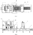
- the continuous sealing and cutting machine of the present invention comprises a machine frame 1, a synchronous filling device 2, a film covering device 3, a synchronous sealing and cutting device 4 and a film collecting device 5.
- the machine frame 1 is provided with a drive device 13;
- the drive device 13 comprises an active drive chain wheel 131, a passive drive chain wheel 132, a drive chain 133 and a motor 134;
- the active drive chain wheel 131 is connected with the motor 134 through a rotation axis 135 for motion transmission;
- the drive chain 133 is mounted on the active drive chain wheel 131 and the passive drive chain wheel 132;
- the motor 134 supplies power to realize transmission of the drive chain 133.
- the drive chain 133 is connected to a template rack via a door-shaped connector 136, thereby driving the template rack to move.
- a template 137 is provided with a positioning column 1371 for positioning during sealing and cutting by a heat sealing and cutting mechanism.
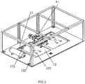
- the machine frame 1 is provided with guiding rails 11; a sliding board 12 is disposed on the guiding rails 11; length of the sliding board 12 is smaller than length of the guiding rail 11; the sliding board 12 can move laterally along the guiding rails 11.
- the sliding board 12 is provided with a screw hole 121 for fixing a heat sealing and cutting unit support and a heat sealing unit support, and a through hole 122 which a cylinder piston can pass through.
- the sliding board 12 is also provided with another screw hole 123 for further securing a heat sealing and cutting module.
- the synchronous filling device 2 comprises a material storage unit 21 and a material feeding unit 22.
- the material storage unit 21 is fixedly provided on the machine frame 1.
- the material feeding unit 22 is mounted to the material storage unit 21 via sliding rods 211 and is fixedly connected to the synchronous sealing and cutting device 4 via a connecting rod 212.
- the material storage unit 21 communicates with the material feeding unit 22 via soft tubes.
- each sliding rod 211 is fixedly connected to the material storage unit 21; another end of which is connected to the material feeding unit 22.
- the material feeding unit 22 can slide along the sliding rods 211.
- the material storage unit 21 is provided with a material feeding valve 213 for material replenishment.
- the material feeding unit 22 comprises material inlets 221 and material outlets 222.
- the material inlets 221 communicate with the material storage unit 21 via soft tubes.
- the material feeding unit 22 is provided with cylinders 223.
- the cylinders 223 control the opening and closing of the material outlets 222 via pistons.
- the material feeding unit 22 is driven by the connecting rod 212 to follow the synchronous sealing and cutting device 4 to slide reciprocally along the sliding rods 211.
- the cylinders 223 control the opening and closing of the material outlets 222.
- the material outlets 222 open and the material feeding unit 22 fills material to the template; on the contrary, after filling material to the template, the material feeding unit 22 slides along the guiding rails in a direction opposite to the moving direction of the template, and the material outlets 222 also closes.
- the sliding speed of the material feeding unit 22 along the sliding rods 211 is the same as the moving speed of the template; during the entire process of material filling, the material feeding unit and the template are maintained in a constant relative position.
- FIG 8 shows a schematic structural view of a film supply unit of the present invention.
- the film covering device 3 comprises the film supply unit and a film feeding unit.
- the film supply unit comprises a film supply motor 311 and a film supply shaft 312 connected to the film supply motor 311 for motion transmission.
- the film supply unit also comprises a film adjustment device 313.
- the film adjustment device 313 comprises springs 3131 and a position limiting rod 3132 for adapting templates of different specifications.
- the film supply unit has to be adjusted in terms of its position so that packaging film can fully cover the template.
- the film adjustment device 313 adjusts the position of the film supply shaft 312 by using the springs 3131 at two ends of the film adjustment device 313, and also uses the position limiting rod 3132 to fix the position thereof.
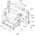
- FIG 9 is a schematic structural view of the film feeding unit of the present invention.
- the film feeding unit comprises a transmission mechanism 321 and a control mechanism 322.
- the transmission mechanism 321 comprises an active transmission axis 3211, a passive transmission axis 3212, a light probe 3213 and a second servo motor 3214.
- the active transmission axis 3211 and the second servo motor 3214 are connected together for motion transmission.
- the passive transmission axis 3212 is in surface contact and coordinates with the active transmission axis 3211.
- the control mechanism 322 comprises a movable shaft 3221, a movable shaft groove 3222 and a proximity switch 3223.
- the movable shaft 3221 can slide along the movable shaft groove 3222.
- the active transmission axis 3211 rotates and drives the passive transmission axis 3212 to rotate. Friction created at the contact surface between the surfaces of the two axes drives the packaging film to move forward.
- the second servo motor 3214 controls the film feeding unit to achieve accurate film feeding.
- the proximity switch 3223 comprises an activation switch 32231 and a deactivation switch 32232.
- the activation switch 32231 is positioned near to an upper end of the movable shaft groove 3222.
- the deactivation switch 32232 is positioned near to a lower end of the movable shaft groove 3222.
- control mechanism 322 is also provided with a film guiding axis 3224.
- the film guiding axis 3224 is positioned higher than the deactivation switch 32232 in terms of vertical height, and is positioned between the movable shaft groove 3222 and the transmission mechanism 321.
- a second film guiding axis 3225 is also provided between the movable shaft groove 3222 and the film supply unit.
- the second film guiding axis 3225 is positioned higher than the activation switch 32231 in terms of vertical height.
- the packaging film runs over an upper end surface of the second film guiding axis 3225, down through a sectional surface thereof, past below a lower end surface of the movable shaft 3221 and finally out from an upper end surface of the film guiding axis 3224.
- the packaging film forms an included angle at the movable shaft 3221. When the transmission mechanism 321 transmits the packaging film, the packaging film is tightened.
- the movable shaft 3221 moves upwardly along the movable shaft groove 3222 until it reaches the same position as the activation switch 32231.
- the film supply motor is energized and the film supply unit starts to supply film. Since film supply by the film supply unit is faster than film feeding by the film feeding unit, the packaging film goes slack and tensional force disappears.
- the movable shaft 3221 therefore slides downwardly along the movable shaft groove 3222 because of its own weight.
- the film supply motor stops rotating and the film feeding unit continues to feed the film, thereby tightening the packaging film again. The above processes of supplying film will be repeated.
- the film feeding unit is provided with the light probe 3213 for identifying the identifiers on the packaging film to further control the length of the film being fed accurately.
- the light probe is provided near to the film guiding axis 3224.
- the light probe 3213 is also provided with a sliding rod 32131.
- the light probe 3213 can move along the sliding rod 32131 and it can move back and forth along a transmission direction of the template and is translatable along a direction perpendicular to the transmission direction of the template in order to adapt to templates of different widths.
- the transmission mechanism also comprises a flat platform 3215.
- the flat platform 3215 is used for flat and smooth covering of the packaging film on the template to prevent crinkle.
- the synchronous sealing and cutting device 4 comprises the first servo motor 41 and the heat sealing and cutting mechanism.
- the first servo motor 41 is fixedly provided on the machine frame.
- the first servo motor 41 and the heat sealing and cutting mechanism are connected for motion transmission.
- the heat sealing and cutting mechanism is mounted on the sliding board 12. The heat sealing and cutting mechanism can follow the sliding board 12 to slide along the guiding rail 11 of the machine frame when driven by the first servo motor 41.
- the heat sealing and cutting mechanism comprises a heat sealing and cutting unit 421 and a heat sealing unit 422.
- the heat sealing and cutting unit 421 and the heat sealing unit 422 are mounted on the sliding board 12.
- the sliding board 12 is slidably connected to the machine frame 1 via the guiding rails 11.
- the sliding board 12 is fixedly provided with a transmission gear rack 121.
- the first servo motor 41 is fixedly provided on the machine frame 1 and is engagingly connected with the transmission gear racks 121. When the first servo motor 41 rotates, the transmission gear racks 121 engaged thereto drives the sliding board 12 to move along the guiding rails so that the heat sealing and cutting unit 421, the heat sealing unit 422 and the material feeding unit are driven to move synchronously under the driving force of the first servo motor 41.
- the heat sealing and cutting unit 421 comprises a support 4211, a cylinder 4212 and a heat sealing and cutting module 4213.
- the support 4211 is mounted on the sliding board 12 and is slidable along the guiding rail 11 of the machine frame.
- the cylinder 4212 is mounted on the sliding board 12.
- the heat sealing and cutting module 4213 is connected with a piston rod 421221 of the cylinder 4212.
- a sustainer plate 4214 is provided at a position corresponding to the heat sealing and cutting module 4213 at a lower end of the support 4211.
- the heat sealing and cutting module 4213 and the sustainer plate 4214 are positioned above and below the template rack respectively.
- the support 4211 comprises an upper cover plate 42111, a lower cover plate 42112 and support columns 42113.
- the support columns are each divided into an upper section and a lower section and secured with the sliding board 12 on the machine frame.
- multiple support rods 42131 are used for connecting the heat sealing and cutting module and the sliding board 12.
- the cylinder comprises a first cylinder 42121 and a second cylinder 42122. Cylinder body of the first cylinder 42121 is connected with cylinder body of the second cylinder. A piston rod of the first cylinder is connected to the upper cover plate. A piston rod 421221 of the second cylinder is connected with a first pressing plate 4215.
- the piston rod 421221 of the second cylinder is connected with the first pressing plate 4215.
- the first pressing plate 4215 is provided with protruding blocks 42151 in the shape of an inverted T.
- a second pressing plate 4216 is disposed corresponding to the first pressing plate 4215.
- the second pressing plate is provided with grooves in the shape of an inverted T corresponding to the first pressing plate 4215.
- the first pressing plate 4215 and the second pressing plate 4216 can slide with respect to each other along the grooves 42161.
- the first pressing plate 4215 and the second pressing plate 4216 are fixed and secured by screw caps.
- Handles 4217 are also provided so that when it is required to replace the components of the heat sealing and cutting module 4213, the second pressing plate 4216 can be pulled out by using the handles 4217 in a direction perpendicular to the sectional surfaces of the grooves 42161. Components of the heat sealing and cutting module 4213 can be adjusted and replaced based on the type of the template on the template rack.
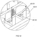
- the heat sealing and cutting module 4213 comprises a heat sealing and cutting mechanism 42132 and cutting blades 42133.
- the heat sealing unit 422 is structurally the same as the heat sealing and cutting unit 421 except that the heat sealing unit 422 is not provided with the cutting blades.
- the first servo motor drives the heat sealing and cutting mechanism 42132 and the material feeding unit to move reciprocally.
- the piston rod 421221 punches downwardly.
- the heat sealing and cutting mechanism 42132 performs the process of heat sealing and adhering and also cutting of the packaging film. During this process, the operating speed of the heat sealing and cutting mechanism 42132 and the transmission speed of the template are the same, thereby maintaining a constant relative position between the heat sealing and cutting mechanism and the template.
Landscapes
- Engineering & Computer Science (AREA)
- Mechanical Engineering (AREA)
- Closing Of Containers (AREA)
- Containers And Plastic Fillers For Packaging (AREA)
- Package Closures (AREA)
- Auxiliary Devices For And Details Of Packaging Control (AREA)
Claims (9)
- Maschine für kontinuierliche Abdichtung und Schneidung mit einem Maschinenrahmen (1), einer Antriebsvorrichtung (13), einer synchronen Füllvorrichtung (2), einer Folienabdeckvorrichtung (3), einer synchronen Abdicht- und Schneidevorrichtung (4) und einer Foliensammelvorrichtung (5); die Antriebsvorrichtung (13) treibt ein Schablonengestell vorwärts; das Schablonengestell wird zum Platzieren von Schablonen (137) verschiedener Spezifikationen verwendet; die synchrone Füllvorrichtung (2), die Folienabdeckvorrichtung (3) und die Foliensammelvorrichtung (5) befinden sich auf dem Maschinenrahmen (1); wobei:die synchrone Füllvorrichtung (2) eine Materiallagereinheit (21) und eine Materialzuführungseinheit (22) umfasst; wobei die Materiallagereinheit (21) auf dem Maschinenrahmen (1) befestigt ist; die Materialzuführungseinheit (22) an die Materiallagereinheit (21) mittels Gleitstangen (211) montiert ist und fest mit der synchronen Abdicht- und Schneidevorrichtung (4) über eine Verbindungsstange (212) verbunden ist; die Materiallagereinheit (21) steht mit der Materialzuführungseinheit (22) durch Schläuche in Verbindung;gekennzeichnet dadurch das die synchrone Abdicht- und Schneidevorrichtung (4) umfasst einen ersten Servomotor (41) und einen Verschweißungs- und Schneidemechanismus; der Verschweißungs- und Schneidemechanismus umfasst eine Verschweißungs- und Schneideeinheit (421) und eine Verschweißungseinheit (422); die Verschweißungs- und Schneideeinheit (421) und die Verschweißungseinheit (422) sind jeweils auf eine Verschiebeplatte (12) montiert; die Verschiebeplatte (12) ist durch Führungsschienen (11) gleitend mit dem Maschinenrahmen (1) verbunden; die Verschiebeplatte (12) ist mit einer Übertragungszahnstange (121) fest verbunden; der erste Servomotor (41) ist auf dem Maschinenrahmen (1) befestigt und greift in die Übertragungszahnstangen (121) ein; die Verschweißungs- und Schneideeinheit (421), die Verschweißungseinheit (422) und die Materialzuführungseinheit (22) werden unter Antriebskraft des ersten Servomotors (41) synchron in Bewegung versetzt.
- Die Maschine für kontinuierliche Abdichtung und Schneidung wie in Anspruch 1, gekennzeichnet dadurch dass: die Verschweißungs- und Schneideeinheit (421) einen Träger (4211), einen Zylinder (4212) und ein Verschweißungs- und Schneidemodul (4213) umfasst; der Träger (4211) ist auf die Verschiebeplatte (12) montiert; der Zylinder (4212) ist auf die Verschiebeplatte (12) montiert; das Verschweißungs- und Schneidemodul (4213) ist mit einer Kolbenstange (421221) des Zylinders (4212) verbunden; eine Stützplatte (4214) ist an dem Ort des Verschweißungs- und Schneidemoduls (4213) an einem unteren Ende des Trägers (4211) vorgesehen; das Verschweißungs- und Schneidemodul (4213) und die Stützplatte (4214) sind oberhalb bzw. unterhalb des Schablonengestells positioniert.
- Maschine für kontinuierliche Abdichtung und Schneidung wie in Anspruch 2, gekennzeichnet dadurch, dass: der Kolbenstab (421221) eines zweiten Zylinders (42122) mit einer ersten Pressplatte (4215) verbunden ist; die erste Pressplatte (4215) mit vorspringenden Blöcken (42151) in Form eines umgekehrten Ts ausgestattet ist; eine zweite Pressplatte (4216) entsprechend der ersten Pressplatte (4215) angebracht ist; die zweite Pressplatte (4216) mit Nuten (42161) in Form eines umgekehrten Ts entsprechend der ersten Pressplatte (4215) ausgestattet ist; die erste Pressplatte (4215) und die zweite Pressplatte (4216) untereinander entlang den Nuten (42161) gleiten.
- Maschine für kontinuierliche Abdichtung und Schneidung wie in Anspruch 1, gekennzeichnet dadurch dass: die Materialzuführungseinheit (22) Materialeinlässe (221) und Materialausgänge (222) umfasst; die Materialeinlässe (221) mit der Materiallagereinheit (21) durch Schläuche in Verbindung stehen; die Materialzuführungseinheit (22) mit Zylindern (223) ausgestattet ist; die Zylinder (223) steuern die Öffnung und Schließung der Materialausgänge (222) mittels Kolben.
- Maschine für kontinuierliche Abdichtung und Schneidung wie in Anspruch 1, gekennzeichnet dadurch dass: die Folienabdeckvorrichtung (3) eine Folienzufuhreinheit und eine Folienversorgungseinheit umfasst; die Folienzufuhreinheit umfasst einen Folienzufuhrmotor (311) und eine Folienzufuhrwelle, die mit dem Folienzufuhrmotor (311) zur Bewegungsübertragung verbunden ist; die Folienversorgungseinheit umfasst einen Übertragungsmechanismus (321) und einen Kontrollmechanismus (322); der Übertragungsmechanismus (321) umfasst eine aktive Übertragungsachse (3211), eine passive Übertragungsachse (3212), einen Lichtleiter (3213) und einen zweiten Servomotor (3214); die aktive Übertragungsachse (3211) und der zweite Servomotor (3214) sind zur Bewegungsübertragung miteinander verbunden; die passive Übertragungsachse (3212) ist in Oberflächenkontakt und koordiniert mit der aktiven Übertragungsachse (3211); der Kontrollmechanismus (322) umfasst eine bewegliche Welle (3221), eine bewegliche Wellennut (3222) und einen Näherungsschalter (3223); die bewegliche Welle (3221) gleitet entlang der beweglichen Wellennut (3222).
- Maschine für kontinuierliche Abdichtung und Schneidung wie in Anspruch 5, gekennzeichnet dadurch dass: der Näherungsschalter (3223) einen Aktivierungsschalter (32231) und einen Deaktivierungsschalter (32232) umfasst; der Aktivierungsschalter (32231) ist an einem oberen Ende der beweglichen Wellennut (3222) positioniert; der Deaktivierungsschalter (32232) ist an einem unteren Ende der beweglichen Wellennut (3222) positioniert; der Aktivierungsschalter (32231) und der Deaktivierungsschalter (32232) steuern die Aktivierung und Deaktivierung des Folienzufuhrmotors (311).
- Maschine für kontinuierliche Abdichtung und Schneidung wie in Anspruch 1, gekennzeichnet dadurch dass: die Antriebsvorrichtung (13) ein aktives Antriebskettenrad (131), eine Antriebskette (133) und ein passives Antriebskettenrad (132) umfasst; die Antriebskette (133) ist auf das aktive Antriebskettenrad (131) und das passive Antriebskettenrad (132) montiert; das aktive Antriebskettenrad (131) ist mit einem Ausstoßende eines Motors (134) zur Bewegungsübertragung verbunden; die Antriebskette (133) und das Schablonengestell sind fest verbunden; die Schablone (137) ist auf dem Schablonengestell befestigt.
- Maschine für kontinuierliche Abdichtung und Schneidung wie in Anspruch 1, gekennzeichnet dadurch, dass die Foliensammelvorrichtung (5) einen Spannmechanismus, eine Foliensammelhaspel und einen Motor umfasst; der Motor weist einen Kupplungsmechanismus auf;
der Spannmechanismus ist mit dem Motor zur Bewegungsübertragung verbunden und ist auch mit der Foliensammelhaspel durch einen Treibriemen zur Bewegungsübertragung verbunden. - Maschine für kontinuierliche Abdichtung und Schneidung nach einem beliebigen der Ansprüche 1-8, gekennzeichnet dadurch, dass: die Folienzufuhreinheit auch eine Folienanpassungsvorrichtung (313) umfasst; die Folienanpassungsvorrichtung (313) umfasst Federn (3131) und einen Lagebegrenzungsstab (3132); eine entsprechende Position zwischen der Folienzufuhreinheit und der Schablone (137) wird unter Verwendung der Federn (3131) in Verbindung mit dem Lagebegrenzungsstab (3132) angepasst.
Applications Claiming Priority (2)
| Application Number | Priority Date | Filing Date | Title |
|---|---|---|---|
| CN 201110302454 CN102328755B (zh) | 2011-10-09 | 2011-10-09 | 连续式封切机 |
| PCT/CN2011/081420 WO2013053154A1 (zh) | 2011-10-09 | 2011-10-27 | 连续式封切机 |
Publications (3)
| Publication Number | Publication Date |
|---|---|
| EP2774859A1 EP2774859A1 (de) | 2014-09-10 |
| EP2774859A4 EP2774859A4 (de) | 2015-09-02 |
| EP2774859B1 true EP2774859B1 (de) | 2016-12-07 |
Family
ID=45480776
Family Applications (1)
| Application Number | Title | Priority Date | Filing Date |
|---|---|---|---|
| EP11873863.2A Not-in-force EP2774859B1 (de) | 2011-10-09 | 2011-10-27 | Maschine für kontinuierliche abdichtung und schneidung |
Country Status (3)
| Country | Link |
|---|---|
| EP (1) | EP2774859B1 (de) |
| CN (1) | CN102328755B (de) |
| WO (1) | WO2013053154A1 (de) |
Families Citing this family (17)
| Publication number | Priority date | Publication date | Assignee | Title |
|---|---|---|---|---|
| CN103264568B (zh) * | 2013-04-19 | 2014-12-24 | 瑞安市诚达机械有限公司 | 纸塑机热封切机构 |
| CN104925332B (zh) * | 2015-05-29 | 2017-03-08 | 辽宁春光机械有限公司 | 全自动液体灌装机单支冲切装置 |
| CN106494702A (zh) * | 2015-09-04 | 2017-03-15 | 广东唐城美特智能工具有限公司 | 蚊钉生产自动化线 |
| CN105857666B (zh) * | 2016-05-21 | 2018-06-08 | 广东粤东机械实业有限公司 | 充填封口机的盖膜定位机构 |
| CN107600488A (zh) * | 2017-08-30 | 2018-01-19 | 蚌埠市同升滤清器有限公司 | 一种pvc发泡板打包装置 |
| CN107877569A (zh) * | 2017-11-08 | 2018-04-06 | 贵州省黄平县乐源旅游特色食品有限公司 | 一种包装膜切割装置 |
| CN108146015A (zh) * | 2017-12-29 | 2018-06-12 | 长兴天誉包装股份有限公司 | 一种自动上料的纸板切割装置 |
| CN111941493B (zh) * | 2019-05-16 | 2022-04-05 | 苏州巨一智能装备有限公司 | 介质膜夹取裁切装置及其方法 |
| CN110104241B (zh) * | 2019-05-28 | 2024-07-23 | 深圳市永创自动化设备有限公司 | 一种底封式塑封机 |
| CN110694484B (zh) * | 2019-10-30 | 2024-11-29 | 本溪华睿思创科技有限公司 | 一种微孔过滤板装膜机 |
| CN110884708A (zh) * | 2019-12-18 | 2020-03-17 | 江苏神翌机械有限公司 | 一种胶囊杯生产用高效高质量切膜机构 |
| CN113320770A (zh) * | 2021-06-21 | 2021-08-31 | 斯蒂尔机械设备(嘉兴)有限公司 | 一种高效的全自动包装机 |
| CN114148589B (zh) * | 2021-12-30 | 2024-07-30 | 江苏神翌机械有限公司 | 一种新型一体成型灌装机 |
| CN114771925B (zh) * | 2022-04-06 | 2024-07-02 | 天津市维之蓝家具制造有限公司 | 一种贴膜装置 |
| CN115285395B (zh) * | 2022-08-17 | 2023-07-04 | 绍兴市盈创医疗科技有限公司 | 一种封装设备 |
| CN115352942B (zh) * | 2022-08-25 | 2025-05-09 | 深圳市新四季信息技术有限公司 | 一种转运基板加工设备 |
| CN120588482B (zh) * | 2025-08-05 | 2025-10-14 | 赣州森泰竹木有限公司 | 一种制造竹木建筑不规则构件的高效覆膜加工装置 |
Family Cites Families (18)
| Publication number | Priority date | Publication date | Assignee | Title |
|---|---|---|---|---|
| US3775934A (en) * | 1972-04-06 | 1973-12-04 | Purity Packaging Ltd | Method of and apparatus for applying caps to containers |
| US3965656A (en) * | 1974-05-16 | 1976-06-29 | Solo Cup Company | Cup filling and capping apparatus |
| US4077180A (en) * | 1976-06-17 | 1978-03-07 | Portion Packaging, Inc. | Method and apparatus for packaging fluent material |
| US4819413A (en) * | 1980-01-23 | 1989-04-11 | Consumers Glass Company Limited | Precision lid fit filling machine |
| US4349997A (en) * | 1980-04-21 | 1982-09-21 | Mitsubishi Jukogyo Kabushiki Kaisha | Device for enabling registry of operations in an apparatus for continuously forming containers filled with material |
| US5443150A (en) * | 1993-09-23 | 1995-08-22 | Rapidpak, Inc. | Apparatus for advancing preformed containers |
| US5992129A (en) * | 1997-03-05 | 1999-11-30 | Tetra Laval Holdings & Finance, Sa | Orienting apparatus for an orientationally sensitive closure |
| DE19750075C2 (de) * | 1997-11-12 | 2002-11-14 | Jagenberg Ag | Verfahren zum Heraustrennen von Deckblattfolien aus einer Kunststoffolienbahn und Vorrichtung zum Durchführen des Verfahrens |
| EA200200139A1 (ru) * | 1999-07-27 | 2002-08-29 | Санфорд Редмонд Инк. | Компактная машина для формования, заполнения и герметичного закрытия упаковок |
| JP4053207B2 (ja) * | 2000-04-03 | 2008-02-27 | シーケーディ株式会社 | 成形充填密封打抜装置 |
| DE10123217A1 (de) * | 2001-05-12 | 2002-11-28 | Bosch Gmbh Robert | Vorrichtung zum Einschieben von Packgut in Packmittel |
| ITMO20030042A1 (it) * | 2003-02-24 | 2004-08-25 | Green Pack Srl | Metodo ed apparato per ottenere contenitori riempiti. |
| JP4360120B2 (ja) * | 2003-05-22 | 2009-11-11 | 澁谷工業株式会社 | 充填シール装置 |
| ITMO20040151A1 (it) * | 2004-06-17 | 2004-09-17 | Evifill S R L | Metodo ed impianto per la fabbricazione di confezioni di prodotti |
| CN201086834Y (zh) * | 2007-08-30 | 2008-07-16 | 江苏永和制药机械有限公司 | 一种易折塑料瓶灌封机热熔封装置 |
| CN201169532Y (zh) * | 2008-03-13 | 2008-12-24 | 山东省蓬莱制药机械厂有限公司 | 一种数控连续液体灌装机 |
| CN201343150Y (zh) * | 2009-01-20 | 2009-11-11 | 广东粤东机械实业有限公司 | 多功能充填旋盖封口机的充填装置 |
| CN202279243U (zh) * | 2011-10-09 | 2012-06-20 | 广东粤东机械实业有限公司 | 连续式封切机 |
-
2011
- 2011-10-09 CN CN 201110302454 patent/CN102328755B/zh not_active Expired - Fee Related
- 2011-10-27 WO PCT/CN2011/081420 patent/WO2013053154A1/zh not_active Ceased
- 2011-10-27 EP EP11873863.2A patent/EP2774859B1/de not_active Not-in-force
Non-Patent Citations (1)
| Title |
|---|
| None * |
Also Published As
| Publication number | Publication date |
|---|---|
| WO2013053154A1 (zh) | 2013-04-18 |
| CN102328755B (zh) | 2013-01-02 |
| CN102328755A (zh) | 2012-01-25 |
| EP2774859A1 (de) | 2014-09-10 |
| EP2774859A4 (de) | 2015-09-02 |
Similar Documents
| Publication | Publication Date | Title |
|---|---|---|
| EP2774859A1 (de) | Maschine für kontinuierliche abdichtung und schneidung | |
| CN101992871B (zh) | 贴标机及具有其的贴标系统 | |
| CN104385420B (zh) | 自动烙印钻孔贴标机 | |
| CN103552183B (zh) | 树脂镜片全自动制模机 | |
| CN110104241B (zh) | 一种底封式塑封机 | |
| CN209288420U (zh) | 一种模具锯床的挡料装置 | |
| CN104385372A (zh) | 全自动刀模横移循环带式裁断机 | |
| CN110281588A (zh) | 一种立体包装袋制袋设备 | |
| CN104178937A (zh) | 一种全自动模板缝纫机 | |
| EP3012195A1 (de) | Verpackungsmaschinenkern sowie verfahren zum erwärmen und kleben geschnittener bänder dafür | |
| CN105398603B (zh) | 一种长条体组装系统 | |
| CN201098915Y (zh) | 自动裁切机 | |
| US20140230618A1 (en) | Deep-drawing packaging machine with lifting device | |
| CN105307417A (zh) | 一种自动贴片流水线上的点胶及检测装置 | |
| CN114290704A (zh) | 闭尾注塑及切断二合一电动注塑机 | |
| CN210590786U (zh) | 一种气泡袋的热压整机 | |
| CN107984801A (zh) | 一种智能纸箱裁切机的纸库调用装置 | |
| CN105014147B (zh) | 一种物料连续输送裁切方法及三轴分量数控飞剪机 | |
| US20230020992A1 (en) | Automatic cushion-attaching device | |
| CN102554344A (zh) | 连续裁切机 | |
| CN102380971A (zh) | 一种加工医疗袋的切片及驱动装置 | |
| CN202480128U (zh) | 全自动斜背式单张模切机 | |
| JP4534847B2 (ja) | 裁断方法および裁断装置 | |
| CN102941591B (zh) | 热成型机的在线分切装置 | |
| CN104264379B (zh) | 一种全自动模板缝纫机用x向传动机构 |
Legal Events
| Date | Code | Title | Description |
|---|---|---|---|
| PUAI | Public reference made under article 153(3) epc to a published international application that has entered the european phase |
Free format text: ORIGINAL CODE: 0009012 |
|
| 17P | Request for examination filed |
Effective date: 20140509 |
|
| AK | Designated contracting states |
Kind code of ref document: A1 Designated state(s): AL AT BE BG CH CY CZ DE DK EE ES FI FR GB GR HR HU IE IS IT LI LT LU LV MC MK MT NL NO PL PT RO RS SE SI SK SM TR |
|
| DAX | Request for extension of the european patent (deleted) | ||
| REG | Reference to a national code |
Ref country code: DE Ref legal event code: R079 Ref document number: 602011033282 Country of ref document: DE Free format text: PREVIOUS MAIN CLASS: B65B0033000000 Ipc: B65B0007160000 |
|
| RA4 | Supplementary search report drawn up and despatched (corrected) |
Effective date: 20150804 |
|
| RIC1 | Information provided on ipc code assigned before grant |
Ipc: B65B 65/02 20060101ALI20150729BHEP Ipc: B65B 39/14 20060101ALI20150729BHEP Ipc: B65B 7/16 20060101AFI20150729BHEP |
|
| GRAP | Despatch of communication of intention to grant a patent |
Free format text: ORIGINAL CODE: EPIDOSNIGR1 |
|
| INTG | Intention to grant announced |
Effective date: 20160422 |
|
| GRAJ | Information related to disapproval of communication of intention to grant by the applicant or resumption of examination proceedings by the epo deleted |
Free format text: ORIGINAL CODE: EPIDOSDIGR1 |
|
| GRAS | Grant fee paid |
Free format text: ORIGINAL CODE: EPIDOSNIGR3 |
|
| GRAP | Despatch of communication of intention to grant a patent |
Free format text: ORIGINAL CODE: EPIDOSNIGR1 |
|
| INTG | Intention to grant announced |
Effective date: 20160908 |
|
| GRAA | (expected) grant |
Free format text: ORIGINAL CODE: 0009210 |
|
| AK | Designated contracting states |
Kind code of ref document: B1 Designated state(s): AL AT BE BG CH CY CZ DE DK EE ES FI FR GB GR HR HU IE IS IT LI LT LU LV MC MK MT NL NO PL PT RO RS SE SI SK SM TR |
|
| REG | Reference to a national code |
Ref country code: GB Ref legal event code: FG4D |
|
| REG | Reference to a national code |
Ref country code: CH Ref legal event code: EP Ref country code: AT Ref legal event code: REF Ref document number: 851449 Country of ref document: AT Kind code of ref document: T Effective date: 20161215 |
|
| REG | Reference to a national code |
Ref country code: IE Ref legal event code: FG4D |
|
| REG | Reference to a national code |
Ref country code: DE Ref legal event code: R096 Ref document number: 602011033282 Country of ref document: DE |
|
| PG25 | Lapsed in a contracting state [announced via postgrant information from national office to epo] |
Ref country code: LV Free format text: LAPSE BECAUSE OF FAILURE TO SUBMIT A TRANSLATION OF THE DESCRIPTION OR TO PAY THE FEE WITHIN THE PRESCRIBED TIME-LIMIT Effective date: 20161207 |
|
| REG | Reference to a national code |
Ref country code: LT Ref legal event code: MG4D |
|
| REG | Reference to a national code |
Ref country code: NL Ref legal event code: MP Effective date: 20161207 |
|
| PG25 | Lapsed in a contracting state [announced via postgrant information from national office to epo] |
Ref country code: SE Free format text: LAPSE BECAUSE OF FAILURE TO SUBMIT A TRANSLATION OF THE DESCRIPTION OR TO PAY THE FEE WITHIN THE PRESCRIBED TIME-LIMIT Effective date: 20161207 Ref country code: LT Free format text: LAPSE BECAUSE OF FAILURE TO SUBMIT A TRANSLATION OF THE DESCRIPTION OR TO PAY THE FEE WITHIN THE PRESCRIBED TIME-LIMIT Effective date: 20161207 Ref country code: NO Free format text: LAPSE BECAUSE OF FAILURE TO SUBMIT A TRANSLATION OF THE DESCRIPTION OR TO PAY THE FEE WITHIN THE PRESCRIBED TIME-LIMIT Effective date: 20170307 Ref country code: GR Free format text: LAPSE BECAUSE OF FAILURE TO SUBMIT A TRANSLATION OF THE DESCRIPTION OR TO PAY THE FEE WITHIN THE PRESCRIBED TIME-LIMIT Effective date: 20170308 |
|
| REG | Reference to a national code |
Ref country code: AT Ref legal event code: MK05 Ref document number: 851449 Country of ref document: AT Kind code of ref document: T Effective date: 20161207 |
|
| PG25 | Lapsed in a contracting state [announced via postgrant information from national office to epo] |
Ref country code: ES Free format text: LAPSE BECAUSE OF FAILURE TO SUBMIT A TRANSLATION OF THE DESCRIPTION OR TO PAY THE FEE WITHIN THE PRESCRIBED TIME-LIMIT Effective date: 20161207 Ref country code: FI Free format text: LAPSE BECAUSE OF FAILURE TO SUBMIT A TRANSLATION OF THE DESCRIPTION OR TO PAY THE FEE WITHIN THE PRESCRIBED TIME-LIMIT Effective date: 20161207 Ref country code: RS Free format text: LAPSE BECAUSE OF FAILURE TO SUBMIT A TRANSLATION OF THE DESCRIPTION OR TO PAY THE FEE WITHIN THE PRESCRIBED TIME-LIMIT Effective date: 20161207 Ref country code: HR Free format text: LAPSE BECAUSE OF FAILURE TO SUBMIT A TRANSLATION OF THE DESCRIPTION OR TO PAY THE FEE WITHIN THE PRESCRIBED TIME-LIMIT Effective date: 20161207 |
|
| PG25 | Lapsed in a contracting state [announced via postgrant information from national office to epo] |
Ref country code: NL Free format text: LAPSE BECAUSE OF FAILURE TO SUBMIT A TRANSLATION OF THE DESCRIPTION OR TO PAY THE FEE WITHIN THE PRESCRIBED TIME-LIMIT Effective date: 20161207 |
|
| PG25 | Lapsed in a contracting state [announced via postgrant information from national office to epo] |
Ref country code: RO Free format text: LAPSE BECAUSE OF FAILURE TO SUBMIT A TRANSLATION OF THE DESCRIPTION OR TO PAY THE FEE WITHIN THE PRESCRIBED TIME-LIMIT Effective date: 20161207 Ref country code: CZ Free format text: LAPSE BECAUSE OF FAILURE TO SUBMIT A TRANSLATION OF THE DESCRIPTION OR TO PAY THE FEE WITHIN THE PRESCRIBED TIME-LIMIT Effective date: 20161207 Ref country code: EE Free format text: LAPSE BECAUSE OF FAILURE TO SUBMIT A TRANSLATION OF THE DESCRIPTION OR TO PAY THE FEE WITHIN THE PRESCRIBED TIME-LIMIT Effective date: 20161207 Ref country code: SK Free format text: LAPSE BECAUSE OF FAILURE TO SUBMIT A TRANSLATION OF THE DESCRIPTION OR TO PAY THE FEE WITHIN THE PRESCRIBED TIME-LIMIT Effective date: 20161207 Ref country code: IS Free format text: LAPSE BECAUSE OF FAILURE TO SUBMIT A TRANSLATION OF THE DESCRIPTION OR TO PAY THE FEE WITHIN THE PRESCRIBED TIME-LIMIT Effective date: 20170407 |
|
| PG25 | Lapsed in a contracting state [announced via postgrant information from national office to epo] |
Ref country code: SM Free format text: LAPSE BECAUSE OF FAILURE TO SUBMIT A TRANSLATION OF THE DESCRIPTION OR TO PAY THE FEE WITHIN THE PRESCRIBED TIME-LIMIT Effective date: 20161207 Ref country code: BE Free format text: LAPSE BECAUSE OF FAILURE TO SUBMIT A TRANSLATION OF THE DESCRIPTION OR TO PAY THE FEE WITHIN THE PRESCRIBED TIME-LIMIT Effective date: 20161207 Ref country code: AT Free format text: LAPSE BECAUSE OF FAILURE TO SUBMIT A TRANSLATION OF THE DESCRIPTION OR TO PAY THE FEE WITHIN THE PRESCRIBED TIME-LIMIT Effective date: 20161207 Ref country code: IT Free format text: LAPSE BECAUSE OF FAILURE TO SUBMIT A TRANSLATION OF THE DESCRIPTION OR TO PAY THE FEE WITHIN THE PRESCRIBED TIME-LIMIT Effective date: 20161207 Ref country code: PT Free format text: LAPSE BECAUSE OF FAILURE TO SUBMIT A TRANSLATION OF THE DESCRIPTION OR TO PAY THE FEE WITHIN THE PRESCRIBED TIME-LIMIT Effective date: 20170407 Ref country code: PL Free format text: LAPSE BECAUSE OF FAILURE TO SUBMIT A TRANSLATION OF THE DESCRIPTION OR TO PAY THE FEE WITHIN THE PRESCRIBED TIME-LIMIT Effective date: 20161207 Ref country code: BG Free format text: LAPSE BECAUSE OF FAILURE TO SUBMIT A TRANSLATION OF THE DESCRIPTION OR TO PAY THE FEE WITHIN THE PRESCRIBED TIME-LIMIT Effective date: 20170307 |
|
| REG | Reference to a national code |
Ref country code: DE Ref legal event code: R097 Ref document number: 602011033282 Country of ref document: DE |
|
| PLBE | No opposition filed within time limit |
Free format text: ORIGINAL CODE: 0009261 |
|
| STAA | Information on the status of an ep patent application or granted ep patent |
Free format text: STATUS: NO OPPOSITION FILED WITHIN TIME LIMIT |
|
| 26N | No opposition filed |
Effective date: 20170908 |
|
| PG25 | Lapsed in a contracting state [announced via postgrant information from national office to epo] |
Ref country code: DK Free format text: LAPSE BECAUSE OF FAILURE TO SUBMIT A TRANSLATION OF THE DESCRIPTION OR TO PAY THE FEE WITHIN THE PRESCRIBED TIME-LIMIT Effective date: 20161207 Ref country code: SI Free format text: LAPSE BECAUSE OF FAILURE TO SUBMIT A TRANSLATION OF THE DESCRIPTION OR TO PAY THE FEE WITHIN THE PRESCRIBED TIME-LIMIT Effective date: 20161207 |
|
| REG | Reference to a national code |
Ref country code: DE Ref legal event code: R119 Ref document number: 602011033282 Country of ref document: DE |
|
| PG25 | Lapsed in a contracting state [announced via postgrant information from national office to epo] |
Ref country code: MC Free format text: LAPSE BECAUSE OF FAILURE TO SUBMIT A TRANSLATION OF THE DESCRIPTION OR TO PAY THE FEE WITHIN THE PRESCRIBED TIME-LIMIT Effective date: 20161207 |
|
| REG | Reference to a national code |
Ref country code: CH Ref legal event code: PL |
|
| GBPC | Gb: european patent ceased through non-payment of renewal fee |
Effective date: 20171027 |
|
| REG | Reference to a national code |
Ref country code: IE Ref legal event code: MM4A |
|
| REG | Reference to a national code |
Ref country code: FR Ref legal event code: ST Effective date: 20180629 |
|
| PG25 | Lapsed in a contracting state [announced via postgrant information from national office to epo] |
Ref country code: GB Free format text: LAPSE BECAUSE OF NON-PAYMENT OF DUE FEES Effective date: 20171027 Ref country code: CH Free format text: LAPSE BECAUSE OF NON-PAYMENT OF DUE FEES Effective date: 20171031 Ref country code: LU Free format text: LAPSE BECAUSE OF NON-PAYMENT OF DUE FEES Effective date: 20171027 Ref country code: LI Free format text: LAPSE BECAUSE OF NON-PAYMENT OF DUE FEES Effective date: 20171031 Ref country code: DE Free format text: LAPSE BECAUSE OF NON-PAYMENT OF DUE FEES Effective date: 20180501 |
|
| PG25 | Lapsed in a contracting state [announced via postgrant information from national office to epo] |
Ref country code: FR Free format text: LAPSE BECAUSE OF NON-PAYMENT OF DUE FEES Effective date: 20171031 |
|
| PG25 | Lapsed in a contracting state [announced via postgrant information from national office to epo] |
Ref country code: MT Free format text: LAPSE BECAUSE OF NON-PAYMENT OF DUE FEES Effective date: 20171027 |
|
| PG25 | Lapsed in a contracting state [announced via postgrant information from national office to epo] |
Ref country code: IE Free format text: LAPSE BECAUSE OF NON-PAYMENT OF DUE FEES Effective date: 20171027 |
|
| PG25 | Lapsed in a contracting state [announced via postgrant information from national office to epo] |
Ref country code: HU Free format text: LAPSE BECAUSE OF FAILURE TO SUBMIT A TRANSLATION OF THE DESCRIPTION OR TO PAY THE FEE WITHIN THE PRESCRIBED TIME-LIMIT; INVALID AB INITIO Effective date: 20111027 |
|
| PG25 | Lapsed in a contracting state [announced via postgrant information from national office to epo] |
Ref country code: CY Free format text: LAPSE BECAUSE OF NON-PAYMENT OF DUE FEES Effective date: 20161207 |
|
| PG25 | Lapsed in a contracting state [announced via postgrant information from national office to epo] |
Ref country code: MK Free format text: LAPSE BECAUSE OF FAILURE TO SUBMIT A TRANSLATION OF THE DESCRIPTION OR TO PAY THE FEE WITHIN THE PRESCRIBED TIME-LIMIT Effective date: 20161207 |
|
| PG25 | Lapsed in a contracting state [announced via postgrant information from national office to epo] |
Ref country code: TR Free format text: LAPSE BECAUSE OF FAILURE TO SUBMIT A TRANSLATION OF THE DESCRIPTION OR TO PAY THE FEE WITHIN THE PRESCRIBED TIME-LIMIT Effective date: 20161207 |
|
| PG25 | Lapsed in a contracting state [announced via postgrant information from national office to epo] |
Ref country code: AL Free format text: LAPSE BECAUSE OF FAILURE TO SUBMIT A TRANSLATION OF THE DESCRIPTION OR TO PAY THE FEE WITHIN THE PRESCRIBED TIME-LIMIT Effective date: 20161207 |