EP2774887B1 - Unité de seuil de porte et procédé pour une unité de porte de palier d'ascenseur - Google Patents
Unité de seuil de porte et procédé pour une unité de porte de palier d'ascenseur Download PDFInfo
- Publication number
- EP2774887B1 EP2774887B1 EP13158386.6A EP13158386A EP2774887B1 EP 2774887 B1 EP2774887 B1 EP 2774887B1 EP 13158386 A EP13158386 A EP 13158386A EP 2774887 B1 EP2774887 B1 EP 2774887B1
- Authority
- EP
- European Patent Office
- Prior art keywords
- door
- unit
- elevator
- landing
- sill
- Prior art date
- Legal status (The legal status is an assumption and is not a legal conclusion. Google has not performed a legal analysis and makes no representation as to the accuracy of the status listed.)
- Active
Links
Images




Classifications
-
- B—PERFORMING OPERATIONS; TRANSPORTING
- B66—HOISTING; LIFTING; HAULING
- B66B—ELEVATORS; ESCALATORS OR MOVING WALKWAYS
- B66B13/00—Doors, gates, or other apparatus controlling access to, or exit from, cages or lift well landings
- B66B13/30—Constructional features of doors or gates
-
- B—PERFORMING OPERATIONS; TRANSPORTING
- B66—HOISTING; LIFTING; HAULING
- B66B—ELEVATORS; ESCALATORS OR MOVING WALKWAYS
- B66B13/00—Doors, gates, or other apparatus controlling access to, or exit from, cages or lift well landings
- B66B13/30—Constructional features of doors or gates
- B66B13/301—Details of door sills
-
- B—PERFORMING OPERATIONS; TRANSPORTING
- B66—HOISTING; LIFTING; HAULING
- B66B—ELEVATORS; ESCALATORS OR MOVING WALKWAYS
- B66B19/00—Mining-hoist operation
-
- B—PERFORMING OPERATIONS; TRANSPORTING
- B66—HOISTING; LIFTING; HAULING
- B66B—ELEVATORS; ESCALATORS OR MOVING WALKWAYS
- B66B9/00—Kinds or types of lifts in, or associated with, buildings or other structures
-
- Y—GENERAL TAGGING OF NEW TECHNOLOGICAL DEVELOPMENTS; GENERAL TAGGING OF CROSS-SECTIONAL TECHNOLOGIES SPANNING OVER SEVERAL SECTIONS OF THE IPC; TECHNICAL SUBJECTS COVERED BY FORMER USPC CROSS-REFERENCE ART COLLECTIONS [XRACs] AND DIGESTS
- Y10—TECHNICAL SUBJECTS COVERED BY FORMER USPC
- Y10T—TECHNICAL SUBJECTS COVERED BY FORMER US CLASSIFICATION
- Y10T29/00—Metal working
- Y10T29/49—Method of mechanical manufacture
- Y10T29/49616—Structural member making
- Y10T29/49623—Static structure, e.g., a building component
Definitions
- the invention relates to a door sill unit for an elevator landing door unit according to the preamble of claim 1.
- the invention also relates to an arrangement in an elevator according to the preamble of claim 6.
- the invention also relates to a method for installing an elevator landing door unit according to the preamble of claim 7.
- An elevator comprises an elevator car moving in a first direction upwards and downwards in an elevator shaft.
- the elevator car transports people and/or goods between the landings in a building.
- the elevator car can thus be stopped at each landing in the building in order for people and or goods to be loaded and/or unloaded to and from the elevator car.
- the elevator landing door unit comprises a frame and at least one door panel.
- the at least one door panel provides a passage between the landing and the car.
- Elevator landing door units have traditionally been installed from the elevator shaft. This means that the lifting machinery and the car platform must be installed in the elevator shaft before the elevator landing door units can be installed.
- the installation has traditionally been done so that a mechanic has first loaded an elevator landing door unit and other necessary equipment on the car platform. The mechanic has then driven with the car platform to the opening at the landing where the elevator landing door unit is to be installed. The mechanic has then begun the mounting of the elevator landing door unit from the car platform in the elevator shaft. He has first attached the sill at the inner wall of the elevator shaft at the lower level of the opening. Then the installation of the elevator landing door unit has proceeded step by step until the installation has been finished. After finishing the installation the mechanic has again driven with the car platform in order to fetch a new elevator landing door unit and so on.
- the constructor of the building has not been able to finalize the entrance at the landings until the elevator landing door units have been installed.
- the finalizing of the entrance at the landings has had to be scheduled to be done after the elevator landing door units have been installed.
- the result of this has been that the finalizing of the entrance at the floors has had to be done at a rather late stage and depending fully of the time table of the elevator installation. There is thus a need to be able to do the installation of the elevator landing door units at an earlier stage in order to avoid the above mentioned problems.
- US patent publication 2006/054419 A1 discloses a door sill unit for an elevator landing door unit.
- the door sill unit shown in figure 8 comprises a bottom support, a support construction extending upwards from the bottom support and a support member being supported with a pivot on the support construction so that the support member is rotatable around the pivot between a first position and a second position.
- An object of the present invention is to solve the problems associated with prior art elevator landing door installations.
- the solution to the problems is to use a door sill unit and to make the installation of the elevator landing door units from the landings instead of from the elevator shaft.
- the door sill unit for an elevator landing door unit is characterized by what is stated in the characterizing portion of claim 1.
- the door sill unit for an elevator landing door unit comprises a bottom support, a support construction extending upwards from the bottom support and a support member being supported with a pivot on the support construction so that the support member is rotatable around the pivot between a first position and a second position.
- the door sill unit is characterized in that the support member is made of a sheet that is bent so that the two branches of the sheet are perpendicular to each other, a first branch forming a support surface and extending in the horizontal direction and a second branch extending in the vertical direction in the first position, an outer edge of said first branch being attached to the pivot.
- the door sill unit is a separate unit which can be positioned on the landing at the opening to the elevator shaft. A part of the door sill unit extends into the elevator shaft and the rest of the door sill unit remains on the landing.
- a temporary sill is attached to the support member of the door sill unit. The support member is rotated around the pivot to the second position so that a groove in the temporary sill opens into the landing.
- the elevator landing door unit is turned in a horizontal position and attached from the bottom of the frame to the support member so that guide means at the bottom of the at least one door panel of the elevator landing door unit sets into the groove in the temporary sill.
- the elevator landing door unit is then rotated into an upright position by rotating the support member around the pivot into the first position.
- the elevator landing door unit is then fastened from the frame at the side walls of the landing at the opening to the elevator shaft. The entrance at the landing can now be finalized by the builder.
- the elevator landing door unit can thus be installed from the landing. There is no need to have the car platform and the lifting machinery ready in the elevator shaft before installing the elevator landing door unit. Even the elevator shaft could still be under construction when the landing door units are installed.
- the elevator landing door unit is installed with a temporary sill, which is short enough to pass through the opening from the landing to the elevator shaft.
- the temporary sill can then later be changed to a permanent sill of full length from the elevator shaft when the lifting machinery and the car platform have been installed.
- the machinery needed to move the at least one door panel can be installed later from the car platform.
- This machinery is mounted on a railing and the railing can be fastened to the wall of the shaft above the elevator landing door unit.
- the railing also comprises a guide rail for the guide elements of the at least one door panel.
- the at least one door panel is thus supported with the guide elements rolling or gliding on the guide rail.
- a connection between the machinery moving the at least one door panel on the car and the machinery moving the at least one door panel in the elevator landing door unit is activated when the car stops at the landing.
- the at least one door panel in the elevator landing door unit and the at least one door panel in the car will thus be moved by the same motor situated in the car.
- Fig. 1 shows a vertical cross section of an elevator.
- the elevator comprises a car 10, an elevator shaft 20, a machine room 30, lifting machinery 40, ropes 41, and a counter weight 42.
- the lifting machinery 40 moves the car 10 in a first direction S1 upwards and downwards in the vertically extending elevator shaft 20.
- the car 10 is carried by the ropes 41, which connect the car 10 to the counter weight 42.
- the car 10 is further supported with guide elements 11 at guide rails 12 extending in the vertical direction in the shaft 20.
- the figure shows only one guide rail 12, but there can be several guide rails 12 on different sides of the car 10.
- the guide elements 11 can comprise rolls rolling on the guide rails 12 or glide elements gliding on the guide rails 12 when the car 10 is mowing upwards and downwards.
- the guide rails 12 are supported with support means 13 at the side wall structure 21 of the elevator shaft 20.
- the figure shows only two support means 13, but there are several support means 13 along the height of the guide rail 12.
- the rolls or glide elements 11 engaging with the guide rails 12 keep the car 10 in position in the horizontal plane when the car 10 moves upwards and downwards in the elevator shaft 20.
- the counter weight 42 is supported in a corresponding way on guide rails supported on the wall structure 21 of the shaft 20.
- the figure also shows the landings L1 to L4 and the landing door units 200.
- the car 10 can be stopped at each landing L1 to L4 so that the floor of the car 10 is at the same level as the floor of the landing L1 to L4.
- the elevator shaft 20 can be formed so that the wall structure 21, 22 is formed of solid walls or so that the wall structure 21, 22 is formed of an open steel structure.
- the car 10 comprises a car door unit comprising at least one door panel opening and closing a passage from the car 10 to the landing L1 to L4.
- Each landing L1 to L4 comprises a corresponding elevator landing door unit 200 comprising a frame and at least one door panel opening and closing a passage from the landing to the car 10.
- the elevator landing door unit comprises normally two door panels sliding in the opposite direction in order to open or close the passage from the landing to the car. Both door panels could, however, also slide in the same direction in a case where there is only space at one side in the elevator shaft for the doors to move. In cases where the elevator shaft is so narrow that it is not possible to use two door panels four door panels i.e. two door panels at each side could be used. This would limit the space needed in the side direction in the elevator shaft. Naturally also only one door panel sliding in either direction would be possible to use when there is enough room for this in the side direction in the elevator shaft. It is naturally not necessary to use sliding door(s), but hinged door(s) could be used instead.
- the door arrangement in the car door unit is adapted to the door arrangement in the elevator landing door unit.
- the car door unit comprises thus a corresponding number of door panels moving in the same way and direction as the door elements in the elevator landing door unit.
- the motor moving the door panels is positioned in the car and the elevator landing door unit is arranged to be connected mechanical-ly to the car door unit so that the door panels in both units move together driven by the same motor.
- Fig. 2 shows a cross section of a door sill unit for an elevator landing door unit according to the invention.
- the door sill unit 100 comprises a bottom support 110 fastened with fastening means 111 to the raw floor RL of the landing.
- the bottom support 110 extends partly into the shaft 20 and comprises regulating means 112 positioned within the shaft 20.
- the door sill unit 100 comprises further a support construction 113 extending vertically upwards from the bottom support 110.
- a support member 120 is attached with a pivot P1 on the support construction 113.
- the support member 120 can be rotated around the pivot P1 between a first position and a second position.
- the support member 120 rotates 90 degrees between the first position and the second position.
- a temporary sill 130 is further attached to the support member 120.
- the temporary sill 130 comprises a groove 131 receiving the guide means positioned at the bottom of the at least one door panel in the elevator landing door unit.
- the correct position of the door sill unit 100 in the horizontal direction is determined so that the edge 141 of the measurement member 140 is on the plum line PL extending vertically in the shaft 20.
- the plum line PL is at a predetermined horizontal distance W1 from the vertical wall structure 22 of the shaft 20.
- the correct height of the support member 120 and thus also the temporary sill 130 is determined with the regulating means 112.
- the regulating means 112 could be formed of a bolt and a nut in which case it is easy to screw the bolt so that the end of the bolt is at a desired height and then lock the bolt with the nut at the bottom support 110.
- the bottom support 110 is in this embodiment formed of a rectangular metal plate.
- the support construction 113 is in this embodiment formed of a metal shaft.
- the support member 120 is in this embodiment formed of a metal sheet that is bent so that the two branches 120A, 120B of the sheet are perpendicular to each other.
- a first branch 120A forms a support surface and extends in a horizontal direction and a second branch extends in a vertical direction downwards when the support member 120 is in the first position.
- An outer edge of the first branch 120A is attached to the pivot P1.
- the temporary sill 130 is attached to the first branch 120A at the fold.
- the second branch 120B prevents visibility from the elevator shaft 20 into the door sill unit 100.
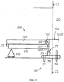
- Fig. 3 shows a cross section of an elevator landing door unit installed on the door sill unit of figure 2 .
- the elevator landing door unit 200 comprises a frame 210 and at least one door panel 220, advantageously two door panels 220.
- the function of the fire labyrinth 212 in normal operation is to prevent the at least one door panel 220 from falling into the elevator shaft 20 in case the supporting machinery that supports the at least one door panel 220 breaks down.
- the support member 120 of the door sill unit 100 has been rotated around the pivot P1 in order to have the temporary sill 130 in a position where the groove 131 opens into the landing.
- the measurement member 140 has been removed from the temporary sill 130.
- the elevator landing door unit 200 is now pushed against the support member 120 so that guide means 221 at the bottom of the at least one door panel 220 set into the groove 131 in the temporary sill 130.
- the frame 210 sets against the support member 120 and is supported from the bottom with fastening means 211 at the support member 120.
- the outer end of the elevator landing door unit 200 can be supported by a suitable support device 300 during this phase of the installation.
- the fastening means 211 at the bottom of the frame 210 could be formed of a snap joint in which case there would be a corresponding snap joint on the support member 120. Snap joints would make the installation faster, but naturally also other fastening means such as bolts and nuts could be used.
- Fig. 4 shows a cross section of the elevator landing door unit of figure 3 in an upright position.
- the elevator landing door unit 200 has now been lifted into an upright position by rotating the elevator landing door unit 200 and the support member 120 in the door sill unit 100 around the pivot P1.
- the elevator landing door unit 200 is now ready to be fastened to the side walls on the landing.
- Fig. 5 shows a front view of the elevator landing door unit 200 according to figure 4 .
- the frame 210 is attached with suitable fastening means 212 e.g. side fixing brackets to the side walls on the landing at the opening to the elevator shaft 20.
- suitable fastening means 212 e.g. side fixing brackets to the side walls on the landing at the opening to the elevator shaft 20.
- the entrance at the landing can now be finished by the builder.
- the builder will make a mortar pouring on the floors of the landings so that the final floor level will rise to a level above the pivot P1 and below the upper edge of the temporary sill 130. Most of the door sill unit 100 will thus be buried into the mortar pouring.
- the final installation of the elevator landing door unit 200 can be done later from the elevator shaft 20 when the lifting machinery 40 and the car platform 10 has been installed into the elevator shaft 20.
- the temporary sill 130 of the elevator landing unit 200 can be changed to a permanent sill.
- the permanent sill is longer than the temporary sill 130 and can be attached to the wall structure 22 of the elevator shaft 20 at the lower end of the elevator landing door unit 200. The longer permanent sill is needed in order to make the opening of the door panels 220 possible.
- the railing comprising the rail and the hanger plate as well as the necessary machinery for supporting and moving the door panels 220 in the elevator landing door unit 200 can also be installed at this later stage from the shaft 20.
- the railing can be attached to the wall structure 22 of the elevator shaft 20.
- the use of the elevator landing door unit according to the invention is not limited to the elevator shown in figure 1 .
- the elevator landing door unit can be used in any elevator e.g. in elevators having a machine room and a counter weight as well as in elevators where there is no machine room and/or no counter weight.
- the wall structure 21, 22 in the shaft 20 can be e.g. a steel construction or a solid wall.
- the door sill unit 100 as well as the elevator landing door unit 200 extends in the lateral direction substantially over the total lateral width of the opening between the landing L1 to L4 and the shaft 20.
- the bottom support 110 could instead of a metal plate be formed e.g. of metal beams attached to each other to form a support surface.
- the support construction 113 could instead of a metal shaft be formed of several inclined metal beams forming a support for the swivel P1.
- the swivel P1 could be arranged with a shaft so that the support member 120 rotates around the shaft.
Landscapes
- Engineering & Computer Science (AREA)
- Automation & Control Theory (AREA)
- Structural Engineering (AREA)
- Elevator Door Apparatuses (AREA)
- Types And Forms Of Lifts (AREA)
- Lift-Guide Devices, And Elevator Ropes And Cables (AREA)
Claims (7)
- Unité de seuil de porte pour une unité de porte de palier d'ascenseur, ladite unité de seuil de porte (100) comprenant un support inférieur (110), une construction support (113) s'étendant vers le haut à partir du support inférieur (110) et un élément support (120) étant supporté avec un pivot (P1) sur la construction support (113) de sorte que l'élément support (120) peut tourner autour du pivot (P1) entre une première position et une seconde position, caractérisée en ce que l'élément support (120) est réalisé à partir d'une feuille qui est pliée de sorte que les deux branches (120A, 120B) de la feuille sont perpendiculaires entre elles, une première branche (120A) formant une surface de support et s'étendant dans la direction horizontale et une seconde branche (120B) s'étendant dans la direction verticale dans la première position, un bord externe de ladite première branche (120A) étant fixé au pivot (P1).
- Unité de seuil de porte selon la revendication 1, caractérisée en ce que l'unité de seuil de porte (100) comprend en outre des moyens de régulation (112) pour réguler la hauteur de l'élément support (120) dans la première position.
- Unité de seuil de porte selon la revendication 2, caractérisée en ce que les moyens de régulation (112) comprennent au moins un boulon s'étendant à travers le support inférieur (110), l'extrémité supérieure du au moins un boulon fixant l'élément support (120), la hauteur de l'élément support (120) étant régulée en montant ou en abaissant le au moins un boulon par rapport au support inférieur (110).
- Unité de seuil de porte selon l'une quelconque des revendications 1 à 3, caractérisée en ce que l'unité de seuil de porte (100) comprend en outre des moyens de fixation (111) pour fixer l'unité de seuil de porte (100) du support inférieur (110) à un plancher d'un palier.
- Unité de seuil de porte selon l'une quelconque des revendications 1 à 4, caractérisée en ce qu'un seuil temporaire (130) est fixé à l'élément support (120).
- Agencement dans un ascenseur, ledit ascenseur comprenant une cabine (10), une machinerie de levage (40) et une gaine (20), ladite machinerie de levage (40) déplaçant la cabine (10) dans une première direction (S1) vers le haut et vers le bas dans la gaine (20) s'étendant verticalement entre les paliers (L1 à L4) dans un bâtiment, chaque palier (L1 à L4) étant prévu avec une unité de porte de palier d'ascenseur (200) positionnée dans l'ouverture entre le palier (L1 à L4) et la gaine (20), ladite unité de porte de palier d'ascenseur (200) comprenant un châssis (210) et au moins un panneau de porte (220), ledit au moins un panneau de porte (220) ouvrant et fermant un passage entre le palier (L1 à L4) et la cabine (10) afin que les passagers et/ou les marchandises pénètrent dans la cabine (10) et/ou sortent de la cabine (10) au niveau du palier (L1 à L4), caractérisé en ce que l'agencement comprend en outre une unité de seuil de porte (100) selon l'une quelconque des revendications 1 à 5 pour supporter l'unité de porte de palier d'ascenseur (200).
- Procédé pour installer une unité de porte de palier d'ascenseur (200) comprenant un châssis (210) et au moins un panneau de porte (220) dans une ouverture entre un palier (L1 à L4) et une gaine d'ascenseur (20), comprenant l'étape consistant à :fixer une unité de seuil de porte (100) au niveau d'un palier (L1 à L4) au niveau de l'ouverture entre le palier (L1 et L4) et la gaine d'ascenseur (20), ladite unité de seuil de porte (100) comprenant un support inférieur (110), une construction support (113) s'étendant vers le haut à partir du support inférieur (110) et un élément support (120) supporté par un pivot (P1) sur la construction support (113) de sorte que l'élément support (120) peut être entraîné en rotation autour du pivot (P1) entre une première position et une seconde position,caractérisé en ce que le procédé comprend en outre les étapes consistant à :fixer un seuil temporaire (130) sur l'élément support (120) et faire tourner l'élément support (120) autour du pivot (P1) dans la seconde position de sorte qu'une rainure (131) dans le seuil temporaire (130) s'ouvre horizontalement sur le palier (L1 à L4),positionner l'unité de porte de palier d'ascenseur (200) dans une position horizontale et fixer l'unité de porte de palier d'ascenseur (200) d'un fond du châssis (210) à l'élément support (120) de sorte que des moyens de guidage (221) au niveau d'un fond du au moins un panneau de porte (220) se placent dans la rainure (131) dans le seuil temporaire (130),faire tourner l'unité de porte de palier d'ascenseur (220) avec l'élément support (120) autour du pivot (P1) dans la première position de sorte que l'unité de porte de palier d'ascenseur (200) est dans une position verticale,fixer l'unité de porte de palier d'ascenseur (200) du châssis (210) aux parois du palier (L1 à L4).
Priority Applications (6)
| Application Number | Priority Date | Filing Date | Title |
|---|---|---|---|
| EP13158386.6A EP2774887B1 (fr) | 2013-03-08 | 2013-03-08 | Unité de seuil de porte et procédé pour une unité de porte de palier d'ascenseur |
| AU2014200928A AU2014200928B2 (en) | 2013-03-08 | 2014-02-21 | Door sill unit and method for an elevator landing door unit |
| RU2014106376A RU2671071C2 (ru) | 2013-03-08 | 2014-02-21 | Лифтовая система, блок дверного порога и способ установки дверного блока лестничной площадки лифта |
| US14/191,056 US9975736B2 (en) | 2013-03-08 | 2014-02-26 | Door sill unit and method for an elevator landing door unit |
| CN201410079800.7A CN104030142B (zh) | 2013-03-08 | 2014-03-06 | 门槛单元、电梯中的配置和用于安装门单元的方法 |
| HK15101724.4A HK1201243B (en) | 2013-03-08 | 2015-02-16 | A door sill unit, arrangement in an elevator, and method for installing a door unit |
Applications Claiming Priority (1)
| Application Number | Priority Date | Filing Date | Title |
|---|---|---|---|
| EP13158386.6A EP2774887B1 (fr) | 2013-03-08 | 2013-03-08 | Unité de seuil de porte et procédé pour une unité de porte de palier d'ascenseur |
Publications (2)
| Publication Number | Publication Date |
|---|---|
| EP2774887A1 EP2774887A1 (fr) | 2014-09-10 |
| EP2774887B1 true EP2774887B1 (fr) | 2016-05-18 |
Family
ID=47832999
Family Applications (1)
| Application Number | Title | Priority Date | Filing Date |
|---|---|---|---|
| EP13158386.6A Active EP2774887B1 (fr) | 2013-03-08 | 2013-03-08 | Unité de seuil de porte et procédé pour une unité de porte de palier d'ascenseur |
Country Status (5)
| Country | Link |
|---|---|
| US (1) | US9975736B2 (fr) |
| EP (1) | EP2774887B1 (fr) |
| CN (1) | CN104030142B (fr) |
| AU (1) | AU2014200928B2 (fr) |
| RU (1) | RU2671071C2 (fr) |
Families Citing this family (5)
| Publication number | Priority date | Publication date | Assignee | Title |
|---|---|---|---|---|
| CN104955754A (zh) * | 2013-02-01 | 2015-09-30 | 通力股份公司 | 电梯系统和用于安装电梯的方法 |
| US10577221B2 (en) * | 2017-05-12 | 2020-03-03 | Otis Elevator Company | Imaging inspection systems and methods for elevator landing doors |
| CN110386532A (zh) * | 2018-04-23 | 2019-10-29 | 上海樱洛机电科技有限公司 | 一种防坠安全机构 |
| JP7107129B2 (ja) * | 2018-09-20 | 2022-07-27 | 三菱電機ビルソリューションズ株式会社 | エレベーターの敷居装置、およびエレベーターの敷居の交換方法 |
| DK181582B1 (en) * | 2023-03-31 | 2024-06-07 | Excellent Holding Aps | Bridge structure and method of providing a smooth transition way across a threshold by means of the bridge structure |
Citations (1)
| Publication number | Priority date | Publication date | Assignee | Title |
|---|---|---|---|---|
| EP1295839A1 (fr) * | 2001-09-24 | 2003-03-26 | Inventio Ag | Méthode et moule pour l'installation d' une porte palière d' un ascenseur |
Family Cites Families (21)
| Publication number | Priority date | Publication date | Assignee | Title |
|---|---|---|---|---|
| US1763858A (en) * | 1924-12-12 | 1930-06-17 | Peelle Co The | Elevator door |
| US1995858A (en) * | 1932-08-25 | 1935-03-26 | Jr William Mearns | Sill construction |
| US2089380A (en) * | 1936-03-23 | 1937-08-10 | Fred W Kammerer | Metallic door saddle |
| US2188049A (en) * | 1937-05-26 | 1940-01-23 | Fred W Kammerer | Threshold |
| US3686808A (en) * | 1971-03-15 | 1972-08-29 | Charles M Loomis | Door frame, sill and facia construction for elevator |
| JPH03223084A (ja) * | 1990-01-25 | 1991-10-02 | Mitsubishi Electric Corp | エレベーターの床合せ装置 |
| JPH06191779A (ja) * | 1992-12-25 | 1994-07-12 | Hitachi Ltd | エレベータのかご |
| US6202798B1 (en) * | 1996-01-25 | 2001-03-20 | Harold S. Friedman | Elevator entrance door assembly and method of installation |
| BR9805943A (pt) * | 1997-03-07 | 1999-08-31 | Kone Corp | Procedimento e aparêlho para instalação de um elevador |
| EP0999169B1 (fr) * | 1998-11-02 | 2004-02-18 | Inventio Ag | Ascenseur dont la salle des machines est située en dessous |
| US6108926A (en) * | 1998-11-30 | 2000-08-29 | Fraser; Robert A. | Tape measure with chalk line, pencil sharpener, friction position holder and stud holder |
| US6938380B2 (en) * | 2001-12-14 | 2005-09-06 | Harold S. Friedman | Elevator entrance sill structure and installation method |
| US7788854B2 (en) * | 2002-09-03 | 2010-09-07 | Harold S. Friedman | Elevator entrance door sill pivotable into and out of elevator shaft via hinge connected support and alignment brackets |
| ES2350312T3 (es) * | 2003-09-18 | 2011-01-21 | Otis Elevator Company | Conjunto de ascensor con umbral extensible. |
| MX2007004966A (es) * | 2004-10-25 | 2007-06-14 | Inventio Ag | Instalacion de elevador comprendiendo un modulo luminoso en el perfil de umbral. |
| US7322555B2 (en) * | 2005-01-10 | 2008-01-29 | The Peelle Company Ltd. | Track jack system |
| US8272481B2 (en) * | 2005-05-10 | 2012-09-25 | Otis Elevator Company | Guide assembly for at least one elevator door |
| KR100742315B1 (ko) * | 2007-01-25 | 2007-07-24 | (주)두성엔티 | 엘리베이터 도어의 이탈 방지 장치 |
| WO2008114344A1 (fr) * | 2007-03-16 | 2008-09-25 | Mitsubishi Electric Corporation | Dispositif d'encadrement de porte pour un ascenseur |
| US8567128B2 (en) * | 2011-01-19 | 2013-10-29 | Endura Products, Inc. | Door sill assemblies with replaceable sill decks |
| JP5799571B2 (ja) * | 2011-05-10 | 2015-10-28 | 三菱電機ビルテクノサービス株式会社 | エレベーター乗場ユニットの運搬装置 |
-
2013
- 2013-03-08 EP EP13158386.6A patent/EP2774887B1/fr active Active
-
2014
- 2014-02-21 AU AU2014200928A patent/AU2014200928B2/en active Active
- 2014-02-21 RU RU2014106376A patent/RU2671071C2/ru active
- 2014-02-26 US US14/191,056 patent/US9975736B2/en active Active
- 2014-03-06 CN CN201410079800.7A patent/CN104030142B/zh active Active
Patent Citations (1)
| Publication number | Priority date | Publication date | Assignee | Title |
|---|---|---|---|---|
| EP1295839A1 (fr) * | 2001-09-24 | 2003-03-26 | Inventio Ag | Méthode et moule pour l'installation d' une porte palière d' un ascenseur |
Also Published As
| Publication number | Publication date |
|---|---|
| EP2774887A1 (fr) | 2014-09-10 |
| HK1201243A1 (en) | 2015-08-28 |
| RU2671071C2 (ru) | 2018-10-29 |
| AU2014200928A1 (en) | 2014-09-25 |
| US9975736B2 (en) | 2018-05-22 |
| US20140251735A1 (en) | 2014-09-11 |
| AU2014200928B2 (en) | 2018-08-30 |
| CN104030142B (zh) | 2018-06-01 |
| CN104030142A (zh) | 2014-09-10 |
| RU2014106376A (ru) | 2015-08-27 |
Similar Documents
| Publication | Publication Date | Title |
|---|---|---|
| AU2007321143B2 (en) | Method and apparatus for installing an elevator without machine room during construction of a building, and use of a hoisting machine | |
| US9975736B2 (en) | Door sill unit and method for an elevator landing door unit | |
| CN111683890B (zh) | 电梯层站门组件及其安装方法 | |
| EP2644811B1 (fr) | Cabine d'ascenseur | |
| US20100018811A1 (en) | Elevators | |
| HK1201243B (en) | A door sill unit, arrangement in an elevator, and method for installing a door unit | |
| KR101307214B1 (ko) | 아파트 건설현장용 승강기 출입 가이드장치 | |
| JP3807851B2 (ja) | エレベータの昇降路 | |
| CN107000976A (zh) | 电梯装置 | |
| JP4037735B2 (ja) | エレベータ構築方法 | |
| JP7811163B2 (ja) | 改修後のエレベータ方式駐車装置および既設のエレベータ方式駐車装置の改修方法 | |
| JP2001080834A (ja) | エレベータ装置及びそのエレベータ制御装置の保守点検方法 | |
| JP2002154770A (ja) | エレベータ | |
| WO2019138545A1 (fr) | Ascenseur et procédé de rénovation s'y rapportant | |
| JP5146076B2 (ja) | エレベータの乗場装置 | |
| HK40060772A (en) | Method for constructing elevator and elevator | |
| CN110550523A (zh) | 一体式加装电梯及其施工方法 | |
| HK40033079B (en) | Elevator landing door assembly and its installation method | |
| HK1131601B (en) | Method and apparatus for installing an elevator without machine room during construction of a building, and use of a hoisting machine | |
| HK1242284A1 (en) | Elevator system door frame that supports guide rails | |
| HK1242284A (en) | Elevator system door frame that supports guide rails | |
| HK1163643B (en) | Elevator system and installation method | |
| BR102012012420A2 (pt) | caixa de corrida metÁlica de elevador com dupla funÇço como elevador de obra e elevador de passageiros | |
| HK1167253A (en) | Elevator system door frame that supports guider rails |
Legal Events
| Date | Code | Title | Description |
|---|---|---|---|
| PUAI | Public reference made under article 153(3) epc to a published international application that has entered the european phase |
Free format text: ORIGINAL CODE: 0009012 |
|
| 17P | Request for examination filed |
Effective date: 20130308 |
|
| AK | Designated contracting states |
Kind code of ref document: A1 Designated state(s): AL AT BE BG CH CY CZ DE DK EE ES FI FR GB GR HR HU IE IS IT LI LT LU LV MC MK MT NL NO PL PT RO RS SE SI SK SM TR |
|
| AX | Request for extension of the european patent |
Extension state: BA ME |
|
| RAP1 | Party data changed (applicant data changed or rights of an application transferred) |
Owner name: KONE CORPORATION |
|
| R17P | Request for examination filed (corrected) |
Effective date: 20141111 |
|
| RBV | Designated contracting states (corrected) |
Designated state(s): AL AT BE BG CH CY CZ DE DK EE ES FI FR GB GR HR HU IE IS IT LI LT LU LV MC MK MT NL NO PL PT RO RS SE SI SK SM TR |
|
| GRAP | Despatch of communication of intention to grant a patent |
Free format text: ORIGINAL CODE: EPIDOSNIGR1 |
|
| INTG | Intention to grant announced |
Effective date: 20151008 |
|
| GRAS | Grant fee paid |
Free format text: ORIGINAL CODE: EPIDOSNIGR3 |
|
| GRAA | (expected) grant |
Free format text: ORIGINAL CODE: 0009210 |
|
| AK | Designated contracting states |
Kind code of ref document: B1 Designated state(s): AL AT BE BG CH CY CZ DE DK EE ES FI FR GB GR HR HU IE IS IT LI LT LU LV MC MK MT NL NO PL PT RO RS SE SI SK SM TR |
|
| REG | Reference to a national code |
Ref country code: GB Ref legal event code: FG4D |
|
| REG | Reference to a national code |
Ref country code: CH Ref legal event code: EP |
|
| REG | Reference to a national code |
Ref country code: IE Ref legal event code: FG4D Ref country code: AT Ref legal event code: REF Ref document number: 800269 Country of ref document: AT Kind code of ref document: T Effective date: 20160615 |
|
| REG | Reference to a national code |
Ref country code: DE Ref legal event code: R096 Ref document number: 602013007515 Country of ref document: DE |
|
| REG | Reference to a national code |
Ref country code: NL Ref legal event code: MP Effective date: 20160518 |
|
| REG | Reference to a national code |
Ref country code: LT Ref legal event code: MG4D |
|
| PG25 | Lapsed in a contracting state [announced via postgrant information from national office to epo] |
Ref country code: NL Free format text: LAPSE BECAUSE OF FAILURE TO SUBMIT A TRANSLATION OF THE DESCRIPTION OR TO PAY THE FEE WITHIN THE PRESCRIBED TIME-LIMIT Effective date: 20160518 Ref country code: LT Free format text: LAPSE BECAUSE OF FAILURE TO SUBMIT A TRANSLATION OF THE DESCRIPTION OR TO PAY THE FEE WITHIN THE PRESCRIBED TIME-LIMIT Effective date: 20160518 Ref country code: FI Free format text: LAPSE BECAUSE OF FAILURE TO SUBMIT A TRANSLATION OF THE DESCRIPTION OR TO PAY THE FEE WITHIN THE PRESCRIBED TIME-LIMIT Effective date: 20160518 Ref country code: NO Free format text: LAPSE BECAUSE OF FAILURE TO SUBMIT A TRANSLATION OF THE DESCRIPTION OR TO PAY THE FEE WITHIN THE PRESCRIBED TIME-LIMIT Effective date: 20160818 |
|
| REG | Reference to a national code |
Ref country code: AT Ref legal event code: MK05 Ref document number: 800269 Country of ref document: AT Kind code of ref document: T Effective date: 20160518 |
|
| PG25 | Lapsed in a contracting state [announced via postgrant information from national office to epo] |
Ref country code: SE Free format text: LAPSE BECAUSE OF FAILURE TO SUBMIT A TRANSLATION OF THE DESCRIPTION OR TO PAY THE FEE WITHIN THE PRESCRIBED TIME-LIMIT Effective date: 20160518 Ref country code: HR Free format text: LAPSE BECAUSE OF FAILURE TO SUBMIT A TRANSLATION OF THE DESCRIPTION OR TO PAY THE FEE WITHIN THE PRESCRIBED TIME-LIMIT Effective date: 20160518 Ref country code: PT Free format text: LAPSE BECAUSE OF FAILURE TO SUBMIT A TRANSLATION OF THE DESCRIPTION OR TO PAY THE FEE WITHIN THE PRESCRIBED TIME-LIMIT Effective date: 20160919 Ref country code: RS Free format text: LAPSE BECAUSE OF FAILURE TO SUBMIT A TRANSLATION OF THE DESCRIPTION OR TO PAY THE FEE WITHIN THE PRESCRIBED TIME-LIMIT Effective date: 20160518 Ref country code: ES Free format text: LAPSE BECAUSE OF FAILURE TO SUBMIT A TRANSLATION OF THE DESCRIPTION OR TO PAY THE FEE WITHIN THE PRESCRIBED TIME-LIMIT Effective date: 20160518 Ref country code: GR Free format text: LAPSE BECAUSE OF FAILURE TO SUBMIT A TRANSLATION OF THE DESCRIPTION OR TO PAY THE FEE WITHIN THE PRESCRIBED TIME-LIMIT Effective date: 20160819 Ref country code: LV Free format text: LAPSE BECAUSE OF FAILURE TO SUBMIT A TRANSLATION OF THE DESCRIPTION OR TO PAY THE FEE WITHIN THE PRESCRIBED TIME-LIMIT Effective date: 20160518 |
|
| PG25 | Lapsed in a contracting state [announced via postgrant information from national office to epo] |
Ref country code: IT Free format text: LAPSE BECAUSE OF FAILURE TO SUBMIT A TRANSLATION OF THE DESCRIPTION OR TO PAY THE FEE WITHIN THE PRESCRIBED TIME-LIMIT Effective date: 20160518 |
|
| PG25 | Lapsed in a contracting state [announced via postgrant information from national office to epo] |
Ref country code: SK Free format text: LAPSE BECAUSE OF FAILURE TO SUBMIT A TRANSLATION OF THE DESCRIPTION OR TO PAY THE FEE WITHIN THE PRESCRIBED TIME-LIMIT Effective date: 20160518 Ref country code: EE Free format text: LAPSE BECAUSE OF FAILURE TO SUBMIT A TRANSLATION OF THE DESCRIPTION OR TO PAY THE FEE WITHIN THE PRESCRIBED TIME-LIMIT Effective date: 20160518 Ref country code: CZ Free format text: LAPSE BECAUSE OF FAILURE TO SUBMIT A TRANSLATION OF THE DESCRIPTION OR TO PAY THE FEE WITHIN THE PRESCRIBED TIME-LIMIT Effective date: 20160518 Ref country code: DK Free format text: LAPSE BECAUSE OF FAILURE TO SUBMIT A TRANSLATION OF THE DESCRIPTION OR TO PAY THE FEE WITHIN THE PRESCRIBED TIME-LIMIT Effective date: 20160518 Ref country code: RO Free format text: LAPSE BECAUSE OF FAILURE TO SUBMIT A TRANSLATION OF THE DESCRIPTION OR TO PAY THE FEE WITHIN THE PRESCRIBED TIME-LIMIT Effective date: 20160518 |
|
| REG | Reference to a national code |
Ref country code: DE Ref legal event code: R097 Ref document number: 602013007515 Country of ref document: DE |
|
| PG25 | Lapsed in a contracting state [announced via postgrant information from national office to epo] |
Ref country code: AT Free format text: LAPSE BECAUSE OF FAILURE TO SUBMIT A TRANSLATION OF THE DESCRIPTION OR TO PAY THE FEE WITHIN THE PRESCRIBED TIME-LIMIT Effective date: 20160518 Ref country code: PL Free format text: LAPSE BECAUSE OF FAILURE TO SUBMIT A TRANSLATION OF THE DESCRIPTION OR TO PAY THE FEE WITHIN THE PRESCRIBED TIME-LIMIT Effective date: 20160518 Ref country code: BE Free format text: LAPSE BECAUSE OF FAILURE TO SUBMIT A TRANSLATION OF THE DESCRIPTION OR TO PAY THE FEE WITHIN THE PRESCRIBED TIME-LIMIT Effective date: 20160518 Ref country code: SM Free format text: LAPSE BECAUSE OF FAILURE TO SUBMIT A TRANSLATION OF THE DESCRIPTION OR TO PAY THE FEE WITHIN THE PRESCRIBED TIME-LIMIT Effective date: 20160518 |
|
| REG | Reference to a national code |
Ref country code: FR Ref legal event code: PLFP Year of fee payment: 5 |
|
| PLBE | No opposition filed within time limit |
Free format text: ORIGINAL CODE: 0009261 |
|
| STAA | Information on the status of an ep patent application or granted ep patent |
Free format text: STATUS: NO OPPOSITION FILED WITHIN TIME LIMIT |
|
| 26N | No opposition filed |
Effective date: 20170221 |
|
| PG25 | Lapsed in a contracting state [announced via postgrant information from national office to epo] |
Ref country code: SI Free format text: LAPSE BECAUSE OF FAILURE TO SUBMIT A TRANSLATION OF THE DESCRIPTION OR TO PAY THE FEE WITHIN THE PRESCRIBED TIME-LIMIT Effective date: 20160518 |
|
| REG | Reference to a national code |
Ref country code: CH Ref legal event code: PL |
|
| PG25 | Lapsed in a contracting state [announced via postgrant information from national office to epo] |
Ref country code: MC Free format text: LAPSE BECAUSE OF FAILURE TO SUBMIT A TRANSLATION OF THE DESCRIPTION OR TO PAY THE FEE WITHIN THE PRESCRIBED TIME-LIMIT Effective date: 20160518 |
|
| REG | Reference to a national code |
Ref country code: IE Ref legal event code: MM4A |
|
| PG25 | Lapsed in a contracting state [announced via postgrant information from national office to epo] |
Ref country code: LU Free format text: LAPSE BECAUSE OF NON-PAYMENT OF DUE FEES Effective date: 20170308 |
|
| PG25 | Lapsed in a contracting state [announced via postgrant information from national office to epo] |
Ref country code: CH Free format text: LAPSE BECAUSE OF NON-PAYMENT OF DUE FEES Effective date: 20170331 Ref country code: LI Free format text: LAPSE BECAUSE OF NON-PAYMENT OF DUE FEES Effective date: 20170331 Ref country code: IE Free format text: LAPSE BECAUSE OF NON-PAYMENT OF DUE FEES Effective date: 20170308 |
|
| REG | Reference to a national code |
Ref country code: FR Ref legal event code: PLFP Year of fee payment: 6 |
|
| PG25 | Lapsed in a contracting state [announced via postgrant information from national office to epo] |
Ref country code: MT Free format text: LAPSE BECAUSE OF NON-PAYMENT OF DUE FEES Effective date: 20170308 |
|
| PG25 | Lapsed in a contracting state [announced via postgrant information from national office to epo] |
Ref country code: AL Free format text: LAPSE BECAUSE OF FAILURE TO SUBMIT A TRANSLATION OF THE DESCRIPTION OR TO PAY THE FEE WITHIN THE PRESCRIBED TIME-LIMIT Effective date: 20160518 |
|
| PG25 | Lapsed in a contracting state [announced via postgrant information from national office to epo] |
Ref country code: HU Free format text: LAPSE BECAUSE OF FAILURE TO SUBMIT A TRANSLATION OF THE DESCRIPTION OR TO PAY THE FEE WITHIN THE PRESCRIBED TIME-LIMIT; INVALID AB INITIO Effective date: 20130308 |
|
| PG25 | Lapsed in a contracting state [announced via postgrant information from national office to epo] |
Ref country code: BG Free format text: LAPSE BECAUSE OF FAILURE TO SUBMIT A TRANSLATION OF THE DESCRIPTION OR TO PAY THE FEE WITHIN THE PRESCRIBED TIME-LIMIT Effective date: 20160518 |
|
| PG25 | Lapsed in a contracting state [announced via postgrant information from national office to epo] |
Ref country code: CY Free format text: LAPSE BECAUSE OF NON-PAYMENT OF DUE FEES Effective date: 20160518 |
|
| PG25 | Lapsed in a contracting state [announced via postgrant information from national office to epo] |
Ref country code: MK Free format text: LAPSE BECAUSE OF FAILURE TO SUBMIT A TRANSLATION OF THE DESCRIPTION OR TO PAY THE FEE WITHIN THE PRESCRIBED TIME-LIMIT Effective date: 20160518 |
|
| PG25 | Lapsed in a contracting state [announced via postgrant information from national office to epo] |
Ref country code: TR Free format text: LAPSE BECAUSE OF FAILURE TO SUBMIT A TRANSLATION OF THE DESCRIPTION OR TO PAY THE FEE WITHIN THE PRESCRIBED TIME-LIMIT Effective date: 20160518 |
|
| PG25 | Lapsed in a contracting state [announced via postgrant information from national office to epo] |
Ref country code: IS Free format text: LAPSE BECAUSE OF FAILURE TO SUBMIT A TRANSLATION OF THE DESCRIPTION OR TO PAY THE FEE WITHIN THE PRESCRIBED TIME-LIMIT Effective date: 20160918 |
|
| P01 | Opt-out of the competence of the unified patent court (upc) registered |
Effective date: 20230525 |
|
| PGFP | Annual fee paid to national office [announced via postgrant information from national office to epo] |
Ref country code: FR Payment date: 20240327 Year of fee payment: 12 |
|
| PG25 | Lapsed in a contracting state [announced via postgrant information from national office to epo] |
Ref country code: FR Free format text: LAPSE BECAUSE OF NON-PAYMENT OF DUE FEES Effective date: 20250331 |
|
| PGFP | Annual fee paid to national office [announced via postgrant information from national office to epo] |
Ref country code: GB Payment date: 20260324 Year of fee payment: 14 |
|
| PGFP | Annual fee paid to national office [announced via postgrant information from national office to epo] |
Ref country code: DE Payment date: 20260319 Year of fee payment: 14 |