EP2775101B1 - Gasturbinenlaufschaufel - Google Patents
Gasturbinenlaufschaufel Download PDFInfo
- Publication number
- EP2775101B1 EP2775101B1 EP14153165.7A EP14153165A EP2775101B1 EP 2775101 B1 EP2775101 B1 EP 2775101B1 EP 14153165 A EP14153165 A EP 14153165A EP 2775101 B1 EP2775101 B1 EP 2775101B1
- Authority
- EP
- European Patent Office
- Prior art keywords
- end wall
- gas turbine
- tip end
- turbine blade
- blade
- Prior art date
- Legal status (The legal status is an assumption and is not a legal conclusion. Google has not performed a legal analysis and makes no representation as to the accuracy of the status listed.)
- Active
Links
Images



Classifications
-
- F—MECHANICAL ENGINEERING; LIGHTING; HEATING; WEAPONS; BLASTING
- F01—MACHINES OR ENGINES IN GENERAL; ENGINE PLANTS IN GENERAL; STEAM ENGINES
- F01D—NON-POSITIVE DISPLACEMENT MACHINES OR ENGINES, e.g. STEAM TURBINES
- F01D5/00—Blades; Blade-carrying members; Heating, heat-insulating, cooling or antivibration means on the blades or the members
- F01D5/12—Blades
- F01D5/14—Form or construction
- F01D5/18—Hollow blades, i.e. blades with cooling or heating channels or cavities; Heating, heat-insulating or cooling means on blades
- F01D5/186—Film cooling
-
- F—MECHANICAL ENGINEERING; LIGHTING; HEATING; WEAPONS; BLASTING
- F01—MACHINES OR ENGINES IN GENERAL; ENGINE PLANTS IN GENERAL; STEAM ENGINES
- F01D—NON-POSITIVE DISPLACEMENT MACHINES OR ENGINES, e.g. STEAM TURBINES
- F01D5/00—Blades; Blade-carrying members; Heating, heat-insulating, cooling or antivibration means on the blades or the members
- F01D5/12—Blades
- F01D5/14—Form or construction
- F01D5/20—Specially-shaped blade tips to seal space between tips and stator
Definitions
- the present invention relates to gas turbines, and more specifically, a gas turbine blade having a cooling structure.
- the efficiency of a gas turbine is improved together with an increase in combustor outlet temperature or turbine inlet temperature.
- the combustor outlet temperature of the current gas turbine reaches 1500 °C.
- the temperature of the surface of a gas turbine blade exposed to the high-temperature combustion gas exceeds a limit temperature of a heat-resistant alloy used, which requires cooling of the gas turbine blade.
- Air extracted from a compressor is supplied to a cooling channel formed in the gas turbine blade, and subjected to convection cooling.
- the air is injected from the cooling channel to the surface of the gas turbine blade via through holes set in the blade surface and flows over the blade surface to perform film cooling, thereby suppressing an increase in temperature of the gas turbine blade to decrease the temperature to the limit temperature or less.
- film cooling holes are difficult to be effectively arranged due to the restrictions on the shape and manufacturing of the blade, and the like.
- the tip of the gas turbine blade In the tip of the gas turbine blade, a combustion gas might leak in clearance between the blade tip and an inner surface of a casing in the radial direction, leading to a loss in work of the turbine. In order to reduce the loss, the clearance is designed to be minimum.
- the tip of the gas turbine blade Upon start-up of the gas turbine, however, a difference in thermal expansion between the gas turbine blade and the casing might be caused due to a difference in temperature between the blade and casing generated in stopping of the turbine, so that the blade tip might be brought into contact with the casing to be worn.
- the tip of the gas turbine blade generally has a partition for isolating the cooling channel formed in the blade from the outside and a blade portion extending from the partition in the direction of the outer diameter to form a tip end wall, which serves as a wear allowance .
- the tip end wall is spaced apart from the cooling channel formed in the gas turbine blade, which makes it difficult to cool the blade tip even though the film cooling holes are provided from the cooling channel toward the blade tip.
- the surface of a space between the adjacent holes is very difficult to be cooled.
- the clearance between the blade tip and the casing in the radial direction is designed to be minimum, another clearance might be generated with the progress of the wear of the tip end wall.
- Patent Document 1 discloses a structure which includes a reinforcement disposed on an inner surface side of a tip end wall of each blade to thereby suppress the generation of local stress in forming film cooling holes at the tip end wall (see Patent Document 1).
- Patent Document 1 expects the outer surface of the tip end wall to be cooled.
- the reinforcements are uniformly provided over its inner surface side of the tip end wall.
- the thickness of the tip end wall is increased, resulting in an increase in thermal capacity of the tip end wall, which is disadvantageous from the viewpoint of suppressing the increase in temperature of the inner surface.
- the reinforcements are provided in a cycle corresponding to positions of the film cooling holes, a superficial area of the inner surface of the blade is increased to promote the heat transfer from the inner surface.
- the difference in temperature between the inner and outer surfaces of the tip end wall can be increased to generate the thermal stress.
- US 6,056,507 A describes a method of preparing a nickel base superalloy inner wall surface of a body open end and an end blade for brazing together at a rim of the end blade, wherein the method includes electro-chemically removing oxides from the inner wall surface.
- US 2005/063824 A1 describes the preamble of claim 1 and in particular a hollow blade comprising an internal cooling passage, an open cavity located at the tip of the blade and bounded by an end wall and a rim and cooling channels that connect the said internal cooling passage to the outer face of the pressure wall.
- the gas turbine blade is provided which can suppress the occurrence of a local stress caused by formation of cooling holes, while suppressing the difference in temperature between the inner and outer surfaces of the tip end wall of the blade.
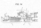
- Fig. 14 shows a cross-sectional view of a typical structure of a gas turbine.
- Fig. 13 shows an example of the gas turbine blade structure including cooling holes.
- the gas turbine mainly includes a compressor 1, a combustor 2, and a turbine 3.
- the compressor 1 performs adiabatic compression on air sucked from the atmosphere as a working fluid.
- the combustor 2 burns the mixture of fuel and the compressed air supplied from the compressor 1 to form a high-temperature and high-pressure gas.
- the turbine 3 generates a rotation power from the combustion gas introduced thereinto from the combustor 2 in expansion of the gas.
- the exhaust gas from the turbine 3 is discharged into the atmosphere.
- rotor blades 4 and stator blades 5 of the gas turbine are alternately arranged in the direction of the turbine axis, and implanted in grooves provided on the outer periphery of a wheel 6.
- Each of the rotor blades 4 shown in Fig. 13 includes a blade portion 7, a platform 8, and a dovetail 9.
- the blade portion 7 includes a concave pressure side portion 12 and a convex suction side portion 13 separated by a boundary between a leading edge 10 first receiving the combustion gas and a trailing edge 11 discharging therefrom the combustion gas.
- the blade tip has a partition 14 for isolating the inside of the blade portion from the outside.
- a tip end wall (to be described later) is provided to extend from the partition toward each of the pressure side and suction side of the blade.
- the gas turbine tends to be subjected to high temperatures in order to improve its efficiency.
- the superficial temperature of the gas turbine blade exposed to the high-temperature combustion gas exceeds a limit temperature of heat-resistant alloy used, which requires the cooling of the gas turbine blade.
- One of cooling methods of a gas turbine blade involves guiding air extracted from an intermediate stage or outlet of the compressor 1 into the cooling channel formed in the blade to thereby cool the air by convective heat transfer through a wall of the channel.
- Another method involves forming in the blade portion 7, cooling holes for connecting a cooling channel inside the blade with the outside of the blade, and injecting cooled air from the cooling holes to cover the blade surface with the cooled air to thereby perform film cooling.
- the film cooling holes are provided in a leading edge 10, a pressure side portion 12, a suction side portion 13, and a tip of the blade portion 7, the platform 8, and the like.
- the tip end wall provided in the tip is spaced apart from the cooling channel formed in the blade. Even when the film cooling hole 17 is provided to be directed from the cooling channel 16 toward the blade tip, the blade tip is difficult to be cooled.
- Reinforcements are provided on the inner surface of the tip end wall, so that an opening for each film cooling hole can be formed close to the blade tip from the viewpoint of strength. To promote cooling of the blade tip, the shape of the reinforcement or the arrangement of the film cooling holes remains an issue.
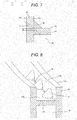
- Figs. 1 to 4 illustrate a cooling structure of the tip of the gas turbine blade representing most the features of the invention.
- the turbine blade 4 of this embodiment includes a tip end wall 15 extending outward in the radial direction from the tip of the blade portion 7.
- the turbine blade 4 also includes outer surface cooling holes 17 making the cooling channel 16 formed in the gas turbine blade communicate with a tip end wall outer surface 15a (space outside the blade), and inner surface cooling holes 18 making the cooling channel 16 communicate with a tip end wall inner surface 15b via the partition 14.
- the inner surface cooling hole 18 is disposed in communication with the tip end wall inner surface 15b (space outside the blade) between two adjacent reinforcements 19 formed at equal intervals together with the outer surface cooling holes 17.
- the reinforcements 19 are provided spaced apart from each other at the boundary between the outer surface of the partition 14 and the inner surface of the tip end wall 15.
- An opening for the inner surface cooling hole 18 is provided in the partition 14, allowing the cooling medium to be injected therefrom along or toward the inner surface of the tip end wall 15.
- An opening for the outer surface cooling hole 17 is provided in the tip end wall outer surface 15a.
- the outer surface cooling hole 17 is disposed to have its part (hole part penetrating the partition 14) superimposed over an arrangement area of the reinforcement 19 as viewed from the outside of the blade portion 7 in the radial direction.
- the reinforcement 19 and the partition 14 can be integrally casted with the blade portion 7.
- the partition 14 can be separately formed from the reinforcement 19 and the blade portion 7, and then can be bonded together by a method, such as welding, as will be described later.
- the outer surface cooling holes 17 and the inner surface cooling holes 18 are processed by electrical discharge machining or the like after forming the blade.
- Fig. 1 shows the settings at the pressure side portion 12.
- the suction side portion 13 can be set in the same way.
- the formationof the reinforcements 19 can position the outer surface cooling holes 17 near the blade tip, and the inner surface cooling holes 18 can be set at the same time, which further reduces the temperature of the tip end wall 15 to suppress the damage to the tip end wall 15 due to the oxidation of the wall by the combustion gas.
- Each of the inner surface cooling holes 18 is disposed in the middle between the adjacent reinforcements 19 to be brought into communication with the tip end wall inner surface 15b, which makes it possible to cool the intermediate part of the outer surface cooling hole 17 from its inner surface side even though the cooling hole 17 is difficult to be cooled.
- the difference in temperature between the inner and outer surfaces of the tip end wall can be reduced, resulting in the state close to the uniform temperature distribution.
- the above structure can reduce the breakage of the tip end wall 15 due to the oxidation or cracks, and can suppress the reduction in blade life and the degradation of the performance of the turbine.
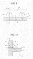
- Figs. 5 to 7 show a cooling structure at the tip of a gas turbine blade in a second embodiment of the invention.
- the turbine blade 4 includes the outer surface cooling holes 17 extending from the cooling channel 16 formed in the gas turbine blade into communication with the tip end wall outer surface 15a, and the inner surface cooling holes 18 extending from the cooling channel 16 into communication with the tip end wall inner surface 15b via the partition 14.
- the reinforcement 19 has a cylindrical shape arranged coaxially with respect to the central axis of the outer surface cooling hole 17, and each of the inner surface cooling holes 18 is disposed in communication with the middle between the adjacent reinforcements 19.
- the cylindrical reinforcement 19 takes the following forms when the central axis of the outer surface cooling hole 17 is positioned in an outer diameter direction with respect to a line of intersection of a surface forming an inner surface 15b of the tip end wall 15 and a surface forming an outer surface 14a of the partition 14.
- the reinforcement 19 positioned in the outer diameter direction with respect to the central axis of the outer surface cooling hole 17 is cylindrical, and the reinforcement 19 positioned in the inner diameter direction with respect to the central axis of the outer surface cooling hole 17 is rectangular.
- the reinforcement 19 is formed in a cylindrical shape, which can reduce an increase in volume of the tip end wall 15 and an increase in thermal capacity caused by the setting of the reinforcement 19 to the minimum.
- the effect of cooling from the surface by the film cooling can be expected to be exhibited inside the tip end wall 15. Further, an increase in superficial area of the tip end wall 15 can be suppressed by the setting of the reinforcement 19, and the heat transfer can be suppressed from the surface of the reinforcement 19.
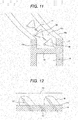
- Fig. 11 shows a cooling structure at the tip of a gas turbine blade in a third embodiment of the invention.
- the turbine blade 4 includes the outer surface cooling holes 17 extending from the cooling channel 16 formed in the gas turbine blade into communication with the tip end wall outer surface 15a, and the inner surface cooling holes 18 extending from the cooling channel 16 into communication with the tip end wall inner surface 15b via the partition 14. Further, inner surface cooling holes 20 are formed to extend from the cooling channel 16 in communication with the reinforcements 19 through the partition 14.
- the cooled air is in communication with not only the outer surface cooling holes 17 and the inner surface cooling holes 18, but also the surface of each of the reinforcements 19 having a high thermal capacity and a large superficial area, which can promote the cooling of the tip end wall 15 to make the temperature distribution of the tip end wall more uniform.
- Fig. 12 shows a cooling structure at the tip of a gas turbine blade in a fourth embodiment of the invention.
- the turbine blade 4 includes the outer surface cooling holes 17 extending from the cooling channel 16 formed in the gas turbine blade into communication with the tip end wall outer surface 15a through the inside of the reinforcements 19, and the inner surface cooling holes 18 extending from the cooling channel 16 into communication with the tip end wall inner surface 15b via the partition 14.
- An opening for the outer surface cooling hole 17 at the tip end wall outer surface 15a, and an opening for the inner surface cooling hole 18 at the partition outer surface 14a are positioned on the trailing edge side with respect to an opening of the cooling channel 16.
- the film cooling is performed by injecting the cooled air toward the trailing edge, so that the cooled air flow in the trailing edge direction can be formed at the surface of the tip end wall 15.
- the cooled air can be sent to the trailing edge of the outer surface of the blade where a cooling hole is not formed easily, which can suppress the damage to the trailing edge due to the oxidation .
- the reinforcements are provided on the inner surface side of the tip end wall of the blade, so that the opening for the outer surface cooling hole can be positioned close to the tip of the tip end wall of the blade.
- the reinforcements having a cylindrical shape are disposed in a cycle to thereby reduce the increase in thickness of the tip end wall and the increase in superficial area of the inner surface of the tip end wall to the minimum, which can reduce the occurrence of the difference in temperature between the inner and outer surfaces of the tip end wall.
- the inner surface cooling holes are provided to be opened on the inner surface side of the tip end wall, and thus can cool the inner and outer surfaces of the tip end wall to suppress the occurrence of the difference in temperature between the inner and outer surfaces.
- the opening for the inner surface cooling hole is located in the middle between the adjacent openings of the outer surface cooling holes, which promotes cooling of an area between the adjacent outer surface cooling holes to make the temperature distribution of the tip end wall uniform.
- the above arrangement can suppress the damage to the tip end wall due to the oxidation by the combustion gas, while suppressing the local stress accompanied by the formation of the cooling holes together with the temperature distribution of the tip end wall, thereby suppressing the occurrence of cracks from the cooling holes.
Landscapes
- Engineering & Computer Science (AREA)
- Mechanical Engineering (AREA)
- General Engineering & Computer Science (AREA)
- Turbine Rotor Nozzle Sealing (AREA)
Claims (6)
- Gasturbinenschaufel, die Folgendes umfasst:einen Kühlkanal (16), der in der Gasturbinenschaufel (4) gebildet ist;eine Abtrennung (14), die auf einer Kopfseite der Gasturbinenschaufel (4) angeordnet ist, um den Kühlkanal (16) von einer Außenseite der Gasturbinenschaufel (4) zu isolieren; undein Kopfstirnwand (15), die derart gebildet ist, dass sie in einer Radialrichtung von einer Spitze eines Schaufelabschnitts zur Außenseite verläuft;mehrere Verstärkungen (19), die entlang einer Abgrenzung zwischen einer Außenfläche der Abtrennung (14) und einer Innenfläche der Kopfstirnwand (15) vorgesehen ist, wobei die Verstärkungen (19) voneinander beabstandet sind;mehrere Außenflächenkühllöcher (17), die vom Kühlkanal (16) in Kommunikation mit einer Außenfläche des Schaufelabschnitts verlaufen; undmehrere Innenflächenkühllöcher (18), die vom Kühlkanal (16) in Kommunikation mit der Innenfläche der Kopfstirnwand (15) durch die Abtrennung (14) verlaufen,dadurch gekennzeichnet, dassein Innenflächenkühlloch (18) zwischen benachbarten Verstärkungen (19) mit dem Kühlkanal (16) und einem Raum außerhalb der Gasturbinenschaufel (4) in Kommunikation ist undeine Öffnung auf einer Auslassseite des Innenflächenkühllochs (18) sich auf der Kopfstirnwandseite der Abtrennung (14) befindet, wobeidas Innenflächenkühlloch (18) gebildet ist, um ein Kühlmedium entlang der Innenfläche der Kopfstirnwand (15) oder zur Innenfläche der Kopfstirnwand (15) einzuspeisen, undein Außenflächenkühlloch (17) derart angeordnet ist, dass es einen Lochteil besitzt, der die Abtrennung (14) durchdringt, die einem Anordnungsbereich einer Verstärkung (19) überlagert ist, wenn der Schaufelabschnitt in der Radialrichtung von außerhalb betrachtet wird.
- Gasturbinenschaufel (4) nach Anspruch 1, wobei das Außenflächenkühlloch (17) eine Öffnung besitzt, die bei einer Außenfläche der Kopfstirnwand (15a) gebildet ist.
- Gasturbinenschaufel (4) nach mindestens einem der Ansprüche 1 bis 2, wobei ein Abstand zwischen Mittelachsen benachbarter Außenflächenkühllöcher (17) gleich oder größer ist als eine Summe aus einem Durchmesser des Innenflächenkühllochs (18) und einer Breite der Verstärkung (19) an einer Position, bei der die Verstärkung (19) die Abtrennung (14) schneidet.
- Gasturbinenschaufel (4) nach mindestens einem der Ansprüche 1 bis 3, wobei die Verstärkung (19) eine zylindrische Form besitzt, die in Bezug auf eine Mittelachse des Außenflächenkühllochs (17) koaxial angeordnet ist.
- Gasturbinenschaufel (4) nach mindestens einem der Ansprüche 1 bis 4, wobei die Mittelachse des Außenflächenkühllochs (17) von einer Schnittlinie der Innenfläche der Kopfstirnwand (15) und der Außenfläche der Abtrennung (14) radial nach außen positioniert ist und
ein Abschnitt der Verstärkung (19), der sich in Bezug auf die Mittelachse des Außenflächenkühllochs (17) radial außerhalb befindet, eine zylindrische Form besitzt, und ein Abschnitt der Verstärkung (19), der sich in Bezug auf die Mittelachse des Außenflächenkühllochs (17) radial innerhalb befindet, eine rechteckige Form besitzt. - Gasturbinenschaufel (4) nach mindestens einem der Ansprüche 1 bis 5, wobei eine Mittelachse beliebiger oder aller Außenflächenkühllöcher (17) und Innenflächenkühllöcher in einer Richtung zu einer Hinterkante der Gasturbinenschaufel (4) geneigt ist.
Applications Claiming Priority (1)
| Application Number | Priority Date | Filing Date | Title |
|---|---|---|---|
| JP2013042496A JP6092661B2 (ja) | 2013-03-05 | 2013-03-05 | ガスタービン翼 |
Publications (2)
| Publication Number | Publication Date |
|---|---|
| EP2775101A1 EP2775101A1 (de) | 2014-09-10 |
| EP2775101B1 true EP2775101B1 (de) | 2020-11-04 |
Family
ID=50028854
Family Applications (1)
| Application Number | Title | Priority Date | Filing Date |
|---|---|---|---|
| EP14153165.7A Active EP2775101B1 (de) | 2013-03-05 | 2014-01-30 | Gasturbinenlaufschaufel |
Country Status (4)
| Country | Link |
|---|---|
| US (1) | US9828859B2 (de) |
| EP (1) | EP2775101B1 (de) |
| JP (1) | JP6092661B2 (de) |
| CN (1) | CN104033186B (de) |
Cited By (1)
| Publication number | Priority date | Publication date | Assignee | Title |
|---|---|---|---|---|
| FR3151232A1 (fr) * | 2023-07-21 | 2025-01-24 | Safran Aircraft Engines | Procede de fabrication d’une aube de turbine de turbomachine |
Families Citing this family (8)
| Publication number | Priority date | Publication date | Assignee | Title |
|---|---|---|---|---|
| CN104775854A (zh) * | 2015-04-23 | 2015-07-15 | 华能国际电力股份有限公司 | 一种具有抑制叶顶泄漏和减小叶顶温度的动叶顶部结构 |
| US10053992B2 (en) | 2015-07-02 | 2018-08-21 | United Technologies Corporation | Gas turbine engine airfoil squealer pocket cooling hole configuration |
| US10156142B2 (en) * | 2015-11-24 | 2018-12-18 | General Electric Company | Systems and methods for producing one or more cooling holes in an airfoil for a gas turbine engine |
| WO2017146680A1 (en) * | 2016-02-23 | 2017-08-31 | Siemens Aktiengesellschaft | Turbine blade squealer tip with vortex disrupting fence |
| KR102028803B1 (ko) * | 2017-09-29 | 2019-10-04 | 두산중공업 주식회사 | 가스 터빈 |
| KR20190096569A (ko) * | 2018-02-09 | 2019-08-20 | 두산중공업 주식회사 | 가스 터빈 |
| CN112031878A (zh) * | 2020-11-05 | 2020-12-04 | 中国航发沈阳黎明航空发动机有限责任公司 | 一种涡轮转子叶片叶尖双层壁结构 |
| KR102727746B1 (ko) * | 2022-02-21 | 2024-11-13 | 국방과학연구소 | 터빈 블레이드 |
Citations (1)
| Publication number | Priority date | Publication date | Assignee | Title |
|---|---|---|---|---|
| US20050063824A1 (en) * | 2003-08-06 | 2005-03-24 | Snecma Moteurs | Hollow rotor blade for the turbine of a gas turbine engine |
Family Cites Families (9)
| Publication number | Priority date | Publication date | Assignee | Title |
|---|---|---|---|---|
| US5672261A (en) * | 1996-08-09 | 1997-09-30 | General Electric Company | Method for brazing an end plate within an open body end, and brazed article |
| US6231307B1 (en) * | 1999-06-01 | 2001-05-15 | General Electric Company | Impingement cooled airfoil tip |
| US6558119B2 (en) * | 2001-05-29 | 2003-05-06 | General Electric Company | Turbine airfoil with separately formed tip and method for manufacture and repair thereof |
| EP1281837A1 (de) | 2001-07-24 | 2003-02-05 | ALSTOM (Switzerland) Ltd | Kühlvorrichtung für Turbinenschaufelspitzen |
| US20030021684A1 (en) * | 2001-07-24 | 2003-01-30 | Downs James P. | Turbine blade tip cooling construction |
| US6554575B2 (en) * | 2001-09-27 | 2003-04-29 | General Electric Company | Ramped tip shelf blade |
| US6824359B2 (en) * | 2003-01-31 | 2004-11-30 | United Technologies Corporation | Turbine blade |
| FR2885645A1 (fr) | 2005-05-13 | 2006-11-17 | Snecma Moteurs Sa | Aube creuse de rotor pour la turbine d'un moteur a turbine a gaz, equipee d'une baignoire |
| US7510376B2 (en) | 2005-08-25 | 2009-03-31 | General Electric Company | Skewed tip hole turbine blade |
-
2013
- 2013-03-05 JP JP2013042496A patent/JP6092661B2/ja active Active
-
2014
- 2014-01-29 CN CN201410043844.4A patent/CN104033186B/zh active Active
- 2014-01-30 EP EP14153165.7A patent/EP2775101B1/de active Active
- 2014-01-30 US US14/168,597 patent/US9828859B2/en active Active
Patent Citations (1)
| Publication number | Priority date | Publication date | Assignee | Title |
|---|---|---|---|---|
| US20050063824A1 (en) * | 2003-08-06 | 2005-03-24 | Snecma Moteurs | Hollow rotor blade for the turbine of a gas turbine engine |
Cited By (2)
| Publication number | Priority date | Publication date | Assignee | Title |
|---|---|---|---|---|
| FR3151232A1 (fr) * | 2023-07-21 | 2025-01-24 | Safran Aircraft Engines | Procede de fabrication d’une aube de turbine de turbomachine |
| WO2025022059A1 (fr) * | 2023-07-21 | 2025-01-30 | Safran Aircraft Engines | Procede de fabrication d'une aube de turbine de turbomachine |
Also Published As
| Publication number | Publication date |
|---|---|
| US9828859B2 (en) | 2017-11-28 |
| US20140255208A1 (en) | 2014-09-11 |
| CN104033186B (zh) | 2016-10-26 |
| EP2775101A1 (de) | 2014-09-10 |
| JP6092661B2 (ja) | 2017-03-08 |
| CN104033186A (zh) | 2014-09-10 |
| JP2014169667A (ja) | 2014-09-18 |
Similar Documents
| Publication | Publication Date | Title |
|---|---|---|
| US9828859B2 (en) | Gas turbine blade with inner and outer cooling holes | |
| US8998565B2 (en) | Apparatus to seal with a turbine blade stage in a gas turbine | |
| US8668453B2 (en) | Cooling system having reduced mass pin fins for components in a gas turbine engine | |
| EP2685048B1 (de) | Gasturbinen-Rotorschaufel und Gasturbine | |
| US8118553B2 (en) | Turbine airfoil cooling system with dual serpentine cooling chambers | |
| EP2412925B1 (de) | Turbinenschaufel und gasturbine | |
| EP2634369B1 (de) | Turbinenschaufel und zugehöriges herstellungsverfahren | |
| EP2392774B1 (de) | Turbinenschaufel mit umfassendem Vorderkantenkühlkanal | |
| CN101622423A (zh) | 燃气涡轮发动机的导叶组件的导叶管道元件 | |
| CN102213109A (zh) | 具有径向冷却孔的涡轮轮叶 | |
| JP2012102726A (ja) | タービンロータブレードのプラットフォーム領域を冷却するための装置、システム、及び方法 | |
| EP2578807A2 (de) | Tragfläche für Turbinensystem | |
| EP4028643B1 (de) | Turbinenschaufel, verfahren zur herstellung einer turbinenschaufel und verfahren zur überholung einer turbinenschaufel | |
| EP2497905A2 (de) | Turbinenschaufel zur Verwendung in Gasturbinenmotoren und Verfahren zu deren Herstellung | |
| US11499435B2 (en) | Gas turbine stator vane, gas turbine provided with same, and method of manufacturing gas turbine stator vane | |
| US20150184523A1 (en) | Structural configurations and cooling circuits in turbine blades | |
| US9890646B2 (en) | Internally cooled airfoil for a rotary machine | |
| WO2017119898A1 (en) | Turbine blade with multi-layer multi-height blade squealer | |
| US20130230407A1 (en) | Turbine Bucket with a Core Cavity Having a Contoured Turn | |
| US11415000B2 (en) | Turbine airfoil with trailing edge features and casting core | |
| EP3803057B1 (de) | Schaufelblatt für einen turbinenmotor mit stiften | |
| CN102650222A (zh) | 涡轮护罩和用于制造涡轮护罩的方法 | |
| US11193378B2 (en) | Turbine airfoil with trailing edge framing features | |
| CN113874600B (zh) | 具有蛇形通道的涡轮叶片 | |
| US12196094B2 (en) | Flow channel forming plate, blade and gas turbine including this, and method of manufacturing flow channel forming plate |
Legal Events
| Date | Code | Title | Description |
|---|---|---|---|
| PUAI | Public reference made under article 153(3) epc to a published international application that has entered the european phase |
Free format text: ORIGINAL CODE: 0009012 |
|
| 17P | Request for examination filed |
Effective date: 20140214 |
|
| AK | Designated contracting states |
Kind code of ref document: A1 Designated state(s): AL AT BE BG CH CY CZ DE DK EE ES FI FR GB GR HR HU IE IS IT LI LT LU LV MC MK MT NL NO PL PT RO RS SE SI SK SM TR |
|
| AX | Request for extension of the european patent |
Extension state: BA ME |
|
| RAP1 | Party data changed (applicant data changed or rights of an application transferred) |
Owner name: MITSUBISHI HITACHI POWER SYSTEMS, LTD. |
|
| STAA | Information on the status of an ep patent application or granted ep patent |
Free format text: STATUS: EXAMINATION IS IN PROGRESS |
|
| 17Q | First examination report despatched |
Effective date: 20191022 |
|
| GRAP | Despatch of communication of intention to grant a patent |
Free format text: ORIGINAL CODE: EPIDOSNIGR1 |
|
| STAA | Information on the status of an ep patent application or granted ep patent |
Free format text: STATUS: GRANT OF PATENT IS INTENDED |
|
| INTG | Intention to grant announced |
Effective date: 20200615 |
|
| GRAS | Grant fee paid |
Free format text: ORIGINAL CODE: EPIDOSNIGR3 |
|
| GRAA | (expected) grant |
Free format text: ORIGINAL CODE: 0009210 |
|
| STAA | Information on the status of an ep patent application or granted ep patent |
Free format text: STATUS: THE PATENT HAS BEEN GRANTED |
|
| REG | Reference to a national code |
Ref country code: DE Ref legal event code: R081 Ref document number: 602014071887 Country of ref document: DE Owner name: MITSUBISHI POWER, LTD., YOKOHAMA, JP Free format text: FORMER OWNER: MITSUBISHI HITACHI POWER SYSTEMS, LTD., YOKOHAMA, JP Ref country code: DE Ref legal event code: R082 Ref document number: 602014071887 Country of ref document: DE Representative=s name: MERH-IP MATIAS ERNY REICHL HOFFMANN PATENTANWA, DE |
|
| AK | Designated contracting states |
Kind code of ref document: B1 Designated state(s): AL AT BE BG CH CY CZ DE DK EE ES FI FR GB GR HR HU IE IS IT LI LT LU LV MC MK MT NL NO PL PT RO RS SE SI SK SM TR |
|
| REG | Reference to a national code |
Ref country code: GB Ref legal event code: FG4D |
|
| REG | Reference to a national code |
Ref country code: CH Ref legal event code: EP |
|
| REG | Reference to a national code |
Ref country code: AT Ref legal event code: REF Ref document number: 1331057 Country of ref document: AT Kind code of ref document: T Effective date: 20201115 |
|
| RAP2 | Party data changed (patent owner data changed or rights of a patent transferred) |
Owner name: MITSUBISHI POWER, LTD. |
|
| REG | Reference to a national code |
Ref country code: DE Ref legal event code: R096 Ref document number: 602014071887 Country of ref document: DE |
|
| REG | Reference to a national code |
Ref country code: IE Ref legal event code: FG4D |
|
| REG | Reference to a national code |
Ref country code: NL Ref legal event code: MP Effective date: 20201104 |
|
| REG | Reference to a national code |
Ref country code: AT Ref legal event code: MK05 Ref document number: 1331057 Country of ref document: AT Kind code of ref document: T Effective date: 20201104 |
|
| PG25 | Lapsed in a contracting state [announced via postgrant information from national office to epo] |
Ref country code: GR Free format text: LAPSE BECAUSE OF FAILURE TO SUBMIT A TRANSLATION OF THE DESCRIPTION OR TO PAY THE FEE WITHIN THE PRESCRIBED TIME-LIMIT Effective date: 20210205 Ref country code: RS Free format text: LAPSE BECAUSE OF FAILURE TO SUBMIT A TRANSLATION OF THE DESCRIPTION OR TO PAY THE FEE WITHIN THE PRESCRIBED TIME-LIMIT Effective date: 20201104 Ref country code: FI Free format text: LAPSE BECAUSE OF FAILURE TO SUBMIT A TRANSLATION OF THE DESCRIPTION OR TO PAY THE FEE WITHIN THE PRESCRIBED TIME-LIMIT Effective date: 20201104 Ref country code: NO Free format text: LAPSE BECAUSE OF FAILURE TO SUBMIT A TRANSLATION OF THE DESCRIPTION OR TO PAY THE FEE WITHIN THE PRESCRIBED TIME-LIMIT Effective date: 20210204 Ref country code: PT Free format text: LAPSE BECAUSE OF FAILURE TO SUBMIT A TRANSLATION OF THE DESCRIPTION OR TO PAY THE FEE WITHIN THE PRESCRIBED TIME-LIMIT Effective date: 20210304 |
|
| PG25 | Lapsed in a contracting state [announced via postgrant information from national office to epo] |
Ref country code: ES Free format text: LAPSE BECAUSE OF FAILURE TO SUBMIT A TRANSLATION OF THE DESCRIPTION OR TO PAY THE FEE WITHIN THE PRESCRIBED TIME-LIMIT Effective date: 20201104 Ref country code: AT Free format text: LAPSE BECAUSE OF FAILURE TO SUBMIT A TRANSLATION OF THE DESCRIPTION OR TO PAY THE FEE WITHIN THE PRESCRIBED TIME-LIMIT Effective date: 20201104 Ref country code: BG Free format text: LAPSE BECAUSE OF FAILURE TO SUBMIT A TRANSLATION OF THE DESCRIPTION OR TO PAY THE FEE WITHIN THE PRESCRIBED TIME-LIMIT Effective date: 20210204 Ref country code: IS Free format text: LAPSE BECAUSE OF FAILURE TO SUBMIT A TRANSLATION OF THE DESCRIPTION OR TO PAY THE FEE WITHIN THE PRESCRIBED TIME-LIMIT Effective date: 20210304 Ref country code: LV Free format text: LAPSE BECAUSE OF FAILURE TO SUBMIT A TRANSLATION OF THE DESCRIPTION OR TO PAY THE FEE WITHIN THE PRESCRIBED TIME-LIMIT Effective date: 20201104 Ref country code: PL Free format text: LAPSE BECAUSE OF FAILURE TO SUBMIT A TRANSLATION OF THE DESCRIPTION OR TO PAY THE FEE WITHIN THE PRESCRIBED TIME-LIMIT Effective date: 20201104 Ref country code: SE Free format text: LAPSE BECAUSE OF FAILURE TO SUBMIT A TRANSLATION OF THE DESCRIPTION OR TO PAY THE FEE WITHIN THE PRESCRIBED TIME-LIMIT Effective date: 20201104 |
|
| REG | Reference to a national code |
Ref country code: LT Ref legal event code: MG9D |
|
| PG25 | Lapsed in a contracting state [announced via postgrant information from national office to epo] |
Ref country code: HR Free format text: LAPSE BECAUSE OF FAILURE TO SUBMIT A TRANSLATION OF THE DESCRIPTION OR TO PAY THE FEE WITHIN THE PRESCRIBED TIME-LIMIT Effective date: 20201104 |
|
| PG25 | Lapsed in a contracting state [announced via postgrant information from national office to epo] |
Ref country code: LT Free format text: LAPSE BECAUSE OF FAILURE TO SUBMIT A TRANSLATION OF THE DESCRIPTION OR TO PAY THE FEE WITHIN THE PRESCRIBED TIME-LIMIT Effective date: 20201104 Ref country code: SK Free format text: LAPSE BECAUSE OF FAILURE TO SUBMIT A TRANSLATION OF THE DESCRIPTION OR TO PAY THE FEE WITHIN THE PRESCRIBED TIME-LIMIT Effective date: 20201104 Ref country code: RO Free format text: LAPSE BECAUSE OF FAILURE TO SUBMIT A TRANSLATION OF THE DESCRIPTION OR TO PAY THE FEE WITHIN THE PRESCRIBED TIME-LIMIT Effective date: 20201104 Ref country code: SM Free format text: LAPSE BECAUSE OF FAILURE TO SUBMIT A TRANSLATION OF THE DESCRIPTION OR TO PAY THE FEE WITHIN THE PRESCRIBED TIME-LIMIT Effective date: 20201104 Ref country code: CZ Free format text: LAPSE BECAUSE OF FAILURE TO SUBMIT A TRANSLATION OF THE DESCRIPTION OR TO PAY THE FEE WITHIN THE PRESCRIBED TIME-LIMIT Effective date: 20201104 Ref country code: EE Free format text: LAPSE BECAUSE OF FAILURE TO SUBMIT A TRANSLATION OF THE DESCRIPTION OR TO PAY THE FEE WITHIN THE PRESCRIBED TIME-LIMIT Effective date: 20201104 |
|
| REG | Reference to a national code |
Ref country code: DE Ref legal event code: R097 Ref document number: 602014071887 Country of ref document: DE |
|
| PG25 | Lapsed in a contracting state [announced via postgrant information from national office to epo] |
Ref country code: DK Free format text: LAPSE BECAUSE OF FAILURE TO SUBMIT A TRANSLATION OF THE DESCRIPTION OR TO PAY THE FEE WITHIN THE PRESCRIBED TIME-LIMIT Effective date: 20201104 Ref country code: MC Free format text: LAPSE BECAUSE OF FAILURE TO SUBMIT A TRANSLATION OF THE DESCRIPTION OR TO PAY THE FEE WITHIN THE PRESCRIBED TIME-LIMIT Effective date: 20201104 |
|
| REG | Reference to a national code |
Ref country code: CH Ref legal event code: PL |
|
| PLBE | No opposition filed within time limit |
Free format text: ORIGINAL CODE: 0009261 |
|
| STAA | Information on the status of an ep patent application or granted ep patent |
Free format text: STATUS: NO OPPOSITION FILED WITHIN TIME LIMIT |
|
| PG25 | Lapsed in a contracting state [announced via postgrant information from national office to epo] |
Ref country code: LU Free format text: LAPSE BECAUSE OF NON-PAYMENT OF DUE FEES Effective date: 20210130 |
|
| REG | Reference to a national code |
Ref country code: BE Ref legal event code: MM Effective date: 20210131 |
|
| 26N | No opposition filed |
Effective date: 20210805 |
|
| GBPC | Gb: european patent ceased through non-payment of renewal fee |
Effective date: 20210204 |
|
| PG25 | Lapsed in a contracting state [announced via postgrant information from national office to epo] |
Ref country code: IT Free format text: LAPSE BECAUSE OF FAILURE TO SUBMIT A TRANSLATION OF THE DESCRIPTION OR TO PAY THE FEE WITHIN THE PRESCRIBED TIME-LIMIT Effective date: 20201104 Ref country code: AL Free format text: LAPSE BECAUSE OF FAILURE TO SUBMIT A TRANSLATION OF THE DESCRIPTION OR TO PAY THE FEE WITHIN THE PRESCRIBED TIME-LIMIT Effective date: 20201104 Ref country code: NL Free format text: LAPSE BECAUSE OF FAILURE TO SUBMIT A TRANSLATION OF THE DESCRIPTION OR TO PAY THE FEE WITHIN THE PRESCRIBED TIME-LIMIT Effective date: 20201104 Ref country code: FR Free format text: LAPSE BECAUSE OF NON-PAYMENT OF DUE FEES Effective date: 20210131 |
|
| PG25 | Lapsed in a contracting state [announced via postgrant information from national office to epo] |
Ref country code: SI Free format text: LAPSE BECAUSE OF FAILURE TO SUBMIT A TRANSLATION OF THE DESCRIPTION OR TO PAY THE FEE WITHIN THE PRESCRIBED TIME-LIMIT Effective date: 20201104 Ref country code: CH Free format text: LAPSE BECAUSE OF NON-PAYMENT OF DUE FEES Effective date: 20210131 Ref country code: LI Free format text: LAPSE BECAUSE OF NON-PAYMENT OF DUE FEES Effective date: 20210131 |
|
| PG25 | Lapsed in a contracting state [announced via postgrant information from national office to epo] |
Ref country code: GB Free format text: LAPSE BECAUSE OF NON-PAYMENT OF DUE FEES Effective date: 20210204 Ref country code: IE Free format text: LAPSE BECAUSE OF NON-PAYMENT OF DUE FEES Effective date: 20210130 |
|
| PG25 | Lapsed in a contracting state [announced via postgrant information from national office to epo] |
Ref country code: IS Free format text: LAPSE BECAUSE OF FAILURE TO SUBMIT A TRANSLATION OF THE DESCRIPTION OR TO PAY THE FEE WITHIN THE PRESCRIBED TIME-LIMIT Effective date: 20210304 |
|
| PG25 | Lapsed in a contracting state [announced via postgrant information from national office to epo] |
Ref country code: BE Free format text: LAPSE BECAUSE OF NON-PAYMENT OF DUE FEES Effective date: 20210131 |
|
| PG25 | Lapsed in a contracting state [announced via postgrant information from national office to epo] |
Ref country code: HU Free format text: LAPSE BECAUSE OF FAILURE TO SUBMIT A TRANSLATION OF THE DESCRIPTION OR TO PAY THE FEE WITHIN THE PRESCRIBED TIME-LIMIT; INVALID AB INITIO Effective date: 20140130 |
|
| PG25 | Lapsed in a contracting state [announced via postgrant information from national office to epo] |
Ref country code: CY Free format text: LAPSE BECAUSE OF FAILURE TO SUBMIT A TRANSLATION OF THE DESCRIPTION OR TO PAY THE FEE WITHIN THE PRESCRIBED TIME-LIMIT Effective date: 20201104 |
|
| PG25 | Lapsed in a contracting state [announced via postgrant information from national office to epo] |
Ref country code: MK Free format text: LAPSE BECAUSE OF FAILURE TO SUBMIT A TRANSLATION OF THE DESCRIPTION OR TO PAY THE FEE WITHIN THE PRESCRIBED TIME-LIMIT Effective date: 20201104 |
|
| PG25 | Lapsed in a contracting state [announced via postgrant information from national office to epo] |
Ref country code: MT Free format text: LAPSE BECAUSE OF FAILURE TO SUBMIT A TRANSLATION OF THE DESCRIPTION OR TO PAY THE FEE WITHIN THE PRESCRIBED TIME-LIMIT Effective date: 20201104 |
|
| PG25 | Lapsed in a contracting state [announced via postgrant information from national office to epo] |
Ref country code: TR Free format text: LAPSE BECAUSE OF FAILURE TO SUBMIT A TRANSLATION OF THE DESCRIPTION OR TO PAY THE FEE WITHIN THE PRESCRIBED TIME-LIMIT Effective date: 20201104 |
|
| PGFP | Annual fee paid to national office [announced via postgrant information from national office to epo] |
Ref country code: DE Payment date: 20251203 Year of fee payment: 13 |