EP2775162B1 - Plaque de talon composite et suspension pneumatique l'utilisant - Google Patents
Plaque de talon composite et suspension pneumatique l'utilisant Download PDFInfo
- Publication number
- EP2775162B1 EP2775162B1 EP14157606.6A EP14157606A EP2775162B1 EP 2775162 B1 EP2775162 B1 EP 2775162B1 EP 14157606 A EP14157606 A EP 14157606A EP 2775162 B1 EP2775162 B1 EP 2775162B1
- Authority
- EP
- European Patent Office
- Prior art keywords
- top plate
- flexible member
- clamp ring
- ring
- air spring
- Prior art date
- Legal status (The legal status is an assumption and is not a legal conclusion. Google has not performed a legal analysis and makes no representation as to the accuracy of the status listed.)
- Active
Links
Images


Classifications
-
- F—MECHANICAL ENGINEERING; LIGHTING; HEATING; WEAPONS; BLASTING
- F16—ENGINEERING ELEMENTS AND UNITS; GENERAL MEASURES FOR PRODUCING AND MAINTAINING EFFECTIVE FUNCTIONING OF MACHINES OR INSTALLATIONS; THERMAL INSULATION IN GENERAL
- F16F—SPRINGS; SHOCK-ABSORBERS; MEANS FOR DAMPING VIBRATION
- F16F9/00—Springs, vibration-dampers, shock-absorbers, or similarly-constructed movement-dampers using a fluid or the equivalent as damping medium
- F16F9/02—Springs, vibration-dampers, shock-absorbers, or similarly-constructed movement-dampers using a fluid or the equivalent as damping medium using gas only or vacuum
- F16F9/04—Springs, vibration-dampers, shock-absorbers, or similarly-constructed movement-dampers using a fluid or the equivalent as damping medium using gas only or vacuum in a chamber with a flexible wall
- F16F9/0454—Springs, vibration-dampers, shock-absorbers, or similarly-constructed movement-dampers using a fluid or the equivalent as damping medium using gas only or vacuum in a chamber with a flexible wall characterised by the assembling method or by the mounting arrangement, e.g. mounting of the membrane
-
- B—PERFORMING OPERATIONS; TRANSPORTING
- B60—VEHICLES IN GENERAL
- B60G—VEHICLE SUSPENSION ARRANGEMENTS
- B60G11/00—Resilient suspensions characterised by arrangement, location or kind of springs
- B60G11/26—Resilient suspensions characterised by arrangement, location or kind of springs having fluid springs only, e.g. hydropneumatic springs
- B60G11/27—Resilient suspensions characterised by arrangement, location or kind of springs having fluid springs only, e.g. hydropneumatic springs wherein the fluid is a gas
-
- F—MECHANICAL ENGINEERING; LIGHTING; HEATING; WEAPONS; BLASTING
- F16—ENGINEERING ELEMENTS AND UNITS; GENERAL MEASURES FOR PRODUCING AND MAINTAINING EFFECTIVE FUNCTIONING OF MACHINES OR INSTALLATIONS; THERMAL INSULATION IN GENERAL
- F16F—SPRINGS; SHOCK-ABSORBERS; MEANS FOR DAMPING VIBRATION
- F16F9/00—Springs, vibration-dampers, shock-absorbers, or similarly-constructed movement-dampers using a fluid or the equivalent as damping medium
- F16F9/02—Springs, vibration-dampers, shock-absorbers, or similarly-constructed movement-dampers using a fluid or the equivalent as damping medium using gas only or vacuum
- F16F9/04—Springs, vibration-dampers, shock-absorbers, or similarly-constructed movement-dampers using a fluid or the equivalent as damping medium using gas only or vacuum in a chamber with a flexible wall
- F16F9/0454—Springs, vibration-dampers, shock-absorbers, or similarly-constructed movement-dampers using a fluid or the equivalent as damping medium using gas only or vacuum in a chamber with a flexible wall characterised by the assembling method or by the mounting arrangement, e.g. mounting of the membrane
- F16F9/0463—Springs, vibration-dampers, shock-absorbers, or similarly-constructed movement-dampers using a fluid or the equivalent as damping medium using gas only or vacuum in a chamber with a flexible wall characterised by the assembling method or by the mounting arrangement, e.g. mounting of the membrane with separate crimping rings
-
- F—MECHANICAL ENGINEERING; LIGHTING; HEATING; WEAPONS; BLASTING
- F16—ENGINEERING ELEMENTS AND UNITS; GENERAL MEASURES FOR PRODUCING AND MAINTAINING EFFECTIVE FUNCTIONING OF MACHINES OR INSTALLATIONS; THERMAL INSULATION IN GENERAL
- F16F—SPRINGS; SHOCK-ABSORBERS; MEANS FOR DAMPING VIBRATION
- F16F9/00—Springs, vibration-dampers, shock-absorbers, or similarly-constructed movement-dampers using a fluid or the equivalent as damping medium
- F16F9/02—Springs, vibration-dampers, shock-absorbers, or similarly-constructed movement-dampers using a fluid or the equivalent as damping medium using gas only or vacuum
- F16F9/04—Springs, vibration-dampers, shock-absorbers, or similarly-constructed movement-dampers using a fluid or the equivalent as damping medium using gas only or vacuum in a chamber with a flexible wall
- F16F9/05—Springs, vibration-dampers, shock-absorbers, or similarly-constructed movement-dampers using a fluid or the equivalent as damping medium using gas only or vacuum in a chamber with a flexible wall the flexible wall being of the rolling diaphragm type
-
- B—PERFORMING OPERATIONS; TRANSPORTING
- B60—VEHICLES IN GENERAL
- B60G—VEHICLE SUSPENSION ARRANGEMENTS
- B60G2202/00—Indexing codes relating to the type of spring, damper or actuator
- B60G2202/10—Type of spring
- B60G2202/15—Fluid spring
- B60G2202/152—Pneumatic spring
-
- B—PERFORMING OPERATIONS; TRANSPORTING
- B60—VEHICLES IN GENERAL
- B60G—VEHICLE SUSPENSION ARRANGEMENTS
- B60G2206/00—Indexing codes related to the manufacturing of suspensions: constructional features, the materials used, procedures or tools
- B60G2206/01—Constructional features of suspension elements, e.g. arms, dampers, springs
- B60G2206/70—Materials used in suspensions
-
- F—MECHANICAL ENGINEERING; LIGHTING; HEATING; WEAPONS; BLASTING
- F16—ENGINEERING ELEMENTS AND UNITS; GENERAL MEASURES FOR PRODUCING AND MAINTAINING EFFECTIVE FUNCTIONING OF MACHINES OR INSTALLATIONS; THERMAL INSULATION IN GENERAL
- F16F—SPRINGS; SHOCK-ABSORBERS; MEANS FOR DAMPING VIBRATION
- F16F2224/00—Materials; Material properties
- F16F2224/02—Materials; Material properties solids
- F16F2224/0241—Fibre-reinforced plastics [FRP]
-
- F—MECHANICAL ENGINEERING; LIGHTING; HEATING; WEAPONS; BLASTING
- F16—ENGINEERING ELEMENTS AND UNITS; GENERAL MEASURES FOR PRODUCING AND MAINTAINING EFFECTIVE FUNCTIONING OF MACHINES OR INSTALLATIONS; THERMAL INSULATION IN GENERAL
- F16F—SPRINGS; SHOCK-ABSORBERS; MEANS FOR DAMPING VIBRATION
- F16F2230/00—Purpose; Design features
- F16F2230/0023—Purpose; Design features protective
Definitions
- the present invention is in the field of air springs. More specifically this invention relates to air springs for use in corrosive environments.
- Air springs have been used as a component of a wide variety of motor vehicles and various other machines and equipment for many years. They are utilized to provide cushioning between movable parts and are primarily employed to absorb shock loads imparted thereon.
- a typical air spring consists of at least one flexible elastomeric reinforced sleeve extending between a pair of retainers, forming a pressurized chamber therein.
- the sleeve typically has a relatively inextensible bead core at each end for securing the sleeve to the retainers. Alternatively, the sleeve may be secured to the retainers by conventional crimping means.
- the fluid in the pressurized chamber generally air, absorbs most of the shock impressed upon or experienced by one of retainers. The retainers move towards and away from each other when the air spring is subjected to forces.
- Both upper and lower retainers are conventionally formed of stamped metal. If the air spring has a piston, the piston, upon which the lower retainer is secured, may be metal or thermoplastic.
- a bumper, mounted on either retainer and provided for impact absorption and transference, is usually thermoplastic or thermoelastic, depending upon the forces which will ultimately be acting on the air spring and the forces to which the bumper will be subjected.
- air springs utilize a steel bead plate which is rolled inwardly to securely affix a flexible member and ensure that there is an air tight seal between the steel bead plate and the flexible member. Because air springs are often used in corrosive environments, the steel bead plate is commonly coated with zinc, paint or some other coating to provide some degree of resistance to corrosion. During the rolling process to join the steel bead plate to the flexible member, the coating is often compromised or destroyed which leads to reduced effectiveness of the coating.
- United States Patent 4,784,376 discloses an improved air spring including: a pair of end members adapted to be mounted at spaced locations; a flexible sleeve formed of an elastomeric material containing reinforcing cords and having open ends sealingly engaged with the end members forming a pressurized fluid chamber therebetween; one of said end members having an end cap extending within one of the open ends of the sleeve and a clamp ring extending about said one sleeve end in clamped engagement with said end cap compressing the sleeve material therebetween; and an annular curved axially extending projection formed on a mating surface of the clamp ring extending into a concave recess formed in a mating surface of the end cap placing the sleeve in compression shear throughout radially spaced annular areas on opposite sides of said projection, and an intervening area within said recess between said annular compressive shear areas having a greater separation than the thickness of the sleeve material to permit the
- United States Patent 6,926,264 discloses an air spring for absorbing and transmitting shock loads between parts moveable relative to one another, the air spring comprising a flexible cylindrical sleeve which is secured at each end to form a fluid chamber therein, a piston, the sleeve being secured at one end to a retainer and being secured at the opposing end by the piston, the air spring being characterized by: the retainer being integrally formed with an intermediate ribbed reinforcement structure to strengthen the retainer, allowing for direct mounting of the air spring to one of the moveable parts, the intermediate ribbed reinforcement structure of the retainer comprising an outer plate and an inner plate which are parallel to each other, and a plurality of ribs that extend between the outer plate and the inner plate.
- United States Patent 7,681,868 discloses an air spring comprising: a roll-off piston; a rolling-lobe flexible member made of rubber or elastomeric material; said rolling-lobe flexible member having a first opening lying opposite said roll-off piston and a second opening assigned to said roll-off piston; an attachment part configured as a head plate; said attachment part being made of thermoplastic or thermoset plastic and having air connection means formed integrally therewith; said attachment part having an outer rim and a conical region also formed integrally therewith; said outer rim and conical region facing toward said rolling-lobe flexible member; said attachment part defining a vulcanization region extending from the side of said rim facing toward said rolling-lobe flexible member into said conical region; and, said rolling-lobe flexible member being tightly vulcanized to said attachment part in said vulcanization region at said first opening while said rolling-lobe flexible member is seated in said vulcanization region.
- EP 0 295 392 A2 and US 2006/0273501 A1 disclose an air spring comprising among others a beadless flexible member, a top plate and a clamp ring. To secure the flexible member in an air-tight manner to the top plate they suggest that the clamp ring and the top plate are comprised of a plurality of mating projections and surfaces. US 2006/0273501 A1 further suggested to make use of a further annular retaining ring. Both solutions are costly and difficult to manufacture.
- the present invention discloses an air spring comprising a piston, a top plate, a clamp ring, a snap ring, and a flexible member which is affixed to the piston and the top plate, wherein the piston, the top plate and the flexible member define a pressurizable chamber, wherein the snap ring is affixed to the clamp ring, wherein the clamp ring affixes an upper portion of the flexible member to the top plate, wherein the clamp ring affixes the snap ring to the top plate, and wherein the top plate is affixed between the snap ring and the flexible member.
- the present invention more specifically discloses an air spring comprising a piston, a top plate, a clamp ring, and a flexible member which is affixed to the piston and the top plate, wherein the piston, the top plate and the flexible member define a pressurizable chamber, wherein the clamp ring is affixed to an upper portion of the flexible member and holds the flexible member in air-tight contact with the top plate, wherein a portion of the clamp ring is deformed over the top of the top plate to hold the flexible member in permanent air-tight contact with the top member, and wherein the top plate is affixed between the upper portion of the flexible member and the deformed portion of the clamp ring.
- the present invention still further discloses an air spring comprising a piston, a top plate, a clamp ring, and a flexible member, wherein the flexible member is affixed to the piston and the top plate to define a pressurizable chamber, wherein the clamp ring is affixed to an upper portion of the flexible member and to the top plate to hold the flexible member in air-tight contact with the top member, wherein clamp ring comprises a plurality of flexible fingers, and wherein the top plate is affixed between the upper portion of the flexible member and the plurality of flexible fingers.
- the present invention further discloses an air spring comprising a piston, a top plate, a clamp ring, a retaining ring, and a flexible member, wherein the flexible member is affixed to the piston and the top plate, wherein the piston, the top plate, and the flexible member define a pressurizable chamber, wherein the clamp ring is affixed to an upper portion of the flexible member, wherein the clamp ring comprises a plurality of clamp ring fingers, wherein the top plate comprises a plurality of top plate fingers, wherein the clamp ring fingers interleave with the top plate fingers, wherein the clamp ring fingers and top plate fingers jointly form a channel which is adapted to accommodate the retaining ring, and wherein relative position between the clamp ring and the top plate is substantially fixed by the retaining ring.
- the present invention still further discloses an air spring comprising a piston, a top plate, a clamp ring, a retaining ring, and a flexible member which is affixed to the piston and the top plate, wherein the piston, the top plate, and the flexible member define a pressurizable chamber, wherein the clamp ring is affixed to an upper portion of the flexible member, wherein the clamp ring comprises a clamp labyrinth, wherein the top plate comprises a top plate labyrinth, wherein the clamp ring labyrinth meshes with the top plate labyrinth, and wherein the clamp ring labyrinth is fused to the top plate labyrinth.
- the present invention further discloses an air spring comprising a piston, a top plate, an external snap ring, and a flexible member which is affixed to the piston and the top plate, wherein the piston, the top plate, and the flexible member define a pressurizable chamber, wherein the top plate is affixed to the external snap ring, and wherein the flexible member is affixed between the external snap ring and the top plate.
- the present invention still further discloses an air spring comprising a piston, a top plate, an upper retaining ring, and a flexible member which is affixed to the piston and the top plate, wherein the piston, the top plate, and the flexible member define a pressurizable chamber, wherein the top plate includes a retaining ring channel, wherein the upper retaining ring includes a mounting wall which fits at least partially within the retaining ring channel, wherein the flexible member is nested in between the upper retaining ring and the top plate, and wherein the mounting wall is nested within the retaining ring channel.
- the top plate will typically be comprised of a polymeric material, such as a fiber filled composite composition.
- the polymeric material can be a fiber filled polyamide, such as a fiber filled nylon-6, nylon-11, nylon-12, nylon-6,6, nylon-4,6, nylon-6,10, and nylon-6,12.
- the fiber utilized in these composite materials is typically a glass fiber.
- the clamp ring is also comprised of a polymeric material which can be the same or different from the material from which is top plate is comprised.
- Figure 1 shows a cross-section of a conventional state of the art air spring 1.
- the conventional state of the art air spring 1 includes a steel bead plate 9, a flexible member 3, and a piston 4.
- the flexible member includes an upper portion of the flexible member 10 which extends from the upper end of the flexible member 12 to no more than 25% along the length of the flexible member 3 from the upper end of the flexible member 12 to the lower end of the flexible member 13.
- the upper portion of the flexible member 10 is adapted to be affixed to the steel bead plate 9 to create an air tight seal.
- the flexible member 3 also includes a lower portion of the flexible member 11 which extends from the lower end of the flexible member 13 to no more than 25% along the length of the flexible member 3 from the lower end of the flexible member 13 to the upper end of the flexible member 12.
- the lower portion of the flexible member 11 is adapted to be affixed to the piston 4 to create an air tight seal.
- the lower portion of the flexible member 11 may be secured in any conventional manner, including, but not limited to, crimping the lower portion of the flexible member 11 to the piston 4 or to a conventional lower retainer or by securing a lower bead core by a lower retainer.
- An internal bumper may be provided for absorbing impact forces.
- the steel bead plate 9, the flexible member 3, and the piston 4 define a pressurizable chamber 14.
- the pressurizable chamber 14 is generally filled with a gas, such as air or nitrogen, to a pressure greater than atmospheric pressure.
- the gas is usually air for economic reasons.
- the pressurizable chamber can optionally be filled with an inert gas, such as nitrogen to help protect the flexible member (a rubber component) from degradation caused by oxygen or ozone.
- the steel bead plate 9 is attached to either a fixed or movable component and the piston 4 is attached to a corresponding fixed or movable component so that loads tending to move the steel bead plate 9 and the piston 4 towards each other will be counteracted by the pressure within the pressurizable chamber 14.
- FIG. 2 shows one embodiment of the present invention.
- This embodiment of the invention includes a top plate 2, a clamp ring 5, and a snap ring 6.
- This embodiment also includes the flexible member 3 and the piston 4 as was used in the conventional state of the art air spring 1.
- the clamp ring 5 is adapted to fit around the outer diameter of the top plate 2.
- the clamp ring includes a compression hook 15 which is adapted to compress the upper portion of the flexible member 10 against the top plate 2 when the three components are assembled together. The compression of the upper portion of the flexible member 10 against the top plate 2 creates an air tight seal.
- the clamp ring 5 includes a snap ring groove 16 which is adapted to accommodate a snap ring 6.
- the snap ring 6 is adapted to fit partially within the snap ring groove 16.
- the top plate 2 and the upper portion of the flexible member 10 are affixed between the snap ring 6 and the compression hook 15.
- the upper portion of the flexible member 10 includes a retention bead 7.
- the retention bead 7 improves the retention of the upper portion of the flexible member 10 in position between the top plate 2 and the compression hook 15.
- the retention bead 7 may consist of steel, polymeric fibers, or any other material which has a greater modulus of elasticity than the material used for the flexible member 3.
- the flexible member 3 is preferably comprised of at least 3 plies: an outer elastomeric ply 54, at least one reinforcing ply 50 formed of elastomeric embedded reinforcing cords, and an inner elastomeric ply 53.
- Assembly of the internal snap ring air spring 17 of this embodiment of the invention is accomplished by positioning the upper portion of the flexible member 10 over the compression hook 15.
- the top plate 2 is then positioned over the upper portion of the flexible member 10.
- the top plate 2 can then be pressed toward the compression hook 15 to compress the upper portion of the flexible member 10 thereby exposing the snap ring groove 16.
- the snap ring 6 can then be positioned into the snap ring groove 16.
- the snap ring 6 retains the top plate 2 in a position that compresses the upper portion of the flexible member 10 between the top plate 2 and the compression hook 15.
- FIG. 3 shows another embodiment of the present invention.
- This embodiment of the invention includes a top plate 2 and a clamp ring 5.
- This embodiment also includes the flexible member 3 and the piston 4 as were used in the conventional state of the art air spring 1.
- the clamp ring 5 is adapted to fit around the outer diameter of the top plate 2.
- the clamp ring includes a compression hook 15 which is adapted to compress the upper portion of the flexible member 10 against the top plate 2 when the three components are assembled together. The compression of the upper portion of the flexible member 10 against the top plate 2 creates an air tight seal.
- the clamp ring 5 includes a deformable rib 19.
- the deformable rib 19 is deformed during the assembly process to create the deformed rib 20.
- the top plate 2 and the upper portion of the flexible member 10 are affixed between the deformed rib 20 and the compression hook 15.
- the upper portion of the flexible member 10 includes a retention bead 7.
- the retention bead 7 improves the retention of the upper portion of the flexible member 10 in position between the top plate 2 and the compression hook 15.
- the retention bead 7 may consist of steel, polymeric fibers, or any other material which has a greater modulus of elasticity than the material used for the flexible member 3.
- Assembly of the deformed ring air spring 18 of this embodiment of the invention is accomplished by positioning the upper portion of the flexible member 10 over the compression hook 15.
- the top plate 2 is then positioned over the upper portion of the flexible member 10.
- the top plate 2 can then be pressed toward the compression hook 15 to compress the upper portion of the flexible member 10.
- the deformable rib 19 may then be deformed to create the deformed rib 20.
- the deformable rib 19 will generally be deformed through a mechanical process.
- the mechanical process may include rolling, compression, staking or any other means known in the art.
- the deformable rib 19 may also be heated to an elevated temperature to assist the mechanical process. The heating of the deformable rib 19 may be from an external heat source or a tool used in the mechanical process.
- the deformed rib 20 retains the top plate 2 in a position that compresses the upper portion of the flexible member 10 between the top plate 2 and the compression hook 15.
- FIGS 4 and 5 show yet another embodiment of the present invention.
- This embodiment of the invention includes a top plate 2 and a clamp ring 5.
- This embodiment also includes the flexible member 3 and the piston 4 as were used in the conventional state of the art air spring 1.
- the clamp ring 5 is adapted to fit around the outer diameter of the top plate 2.
- the clamp ring includes a compression hook 15 which is adapted to compress the upper portion of the flexible member 10 against the top plate 2 when the three components are assembled together. The compression of the upper portion of the flexible member 10 against the top plate 2 creates an air tight seal.
- Assembly of the external finger air spring 21 of this embodiment of the invention is accomplished by positioning the upper portion of the flexible member 10 over the compression hook 15.
- the top plate 2 is then positioned over the upper portion of the flexible member 10.
- the top plate 2 can then be pressed toward the compression hook 15 to compress the upper portion of the flexible member 10.
- the clamp ring has a plurality of flexible fingers 23 extending from the ring in a direction substantially parallel to the center axis of the clamp ring 5.
- the plurality of flexible fingers 23 expand around the outer circumference of the top plate 2 as the top plate is pressed past the plurality of flexible fingers 23.
- the plurality of flexible fingers 23 lock onto the top surface of the top plate 2 through locking flats 22.
- the plurality of flexible fingers 23 retain the top plate 2 in a position that compresses the upper portion of the flexible member 10 between the top plate 2 and the compression hook 15.
- the top plate 2 and the upper portion of the flexible member 10 are affixed between the locking flats 22 and the compression hook 15.
- the upper portion of the flexible member 10 includes a retention bead 7.
- the retention bead 7 improves the retention of the upper portion of the flexible member 10 in position between the top plate 2 and the compression hook 15.
- the retention bead 7 may consist of steel, polymeric fibers, or any other material which has a greater modulus of elasticity than the material used for the flexible member 3.
- the top plate 2 will include a finger receiving ledge 57 and may optionally include a plurality of finger receiving ports 26.
- the plurality of finger receiving ports 26 are adapted to interact with the plurality of flexible fingers 23 on the clamp ring 5.
- the plurality of flexible fingers 23 lock onto the plurality of finger receiving ports through locking flats 22.
- the plurality of locking flats 22 are separated by a plurality of ribs 24.
- the plurality of ribs 24 provide not only additional structural support, but also provide an anti-rotation feature to prevent rotation of the clamp ring 5 relative to the top plate 2.
- the external finger air spring 21 may also optionally include a locking ring 25 that is affixed around the plurality of flexible fingers 23.
- the locking ring 25 is positioned in such a manner that the locking ring 25 restrains movement of the plurality of flexible fingers 23 away from the outer circumference of the top plate 2. Because the locking ring 25 restrains displacement of the plurality of flexible fingers 23, the external finger air spring 21 can withstand much higher forces before the clamp ring 5 becomes unattached from the top plate 2 when utilizing the locking ring 25 than it can withstand without the locking ring 25.
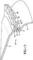
- FIG. 6 and 7 shows still another embodiment of the present invention.
- This embodiment of the invention includes a top plate 2, a clamp ring 5 and a retaining ring 28.
- This embodiment also includes the flexible member 3 and the piston 4 as were used in the conventional state of the art air spring 1.
- the clamp ring 5 includes a plurality of clamp ring fingers 29 which are adapted to interleave with top plate fingers 30 which extend from the outer circumference of the top plate 2. When the clamp ring fingers 29 interleave with the top plate fingers 30, they jointly form a channel 31 which is adapted to accommodate the retaining ring 28.
- the clamp ring includes a compression hook 15 which is adapted to compress the upper portion of the flexible member 10 against the top plate 2 when the three components are assembled together. The compression of the upper portion of the flexible member 10 against the top plate 2 creates an air tight seal.
- the upper portion of the flexible member 10 is affixed between the top plate 2 and the compression hook 15.
- the upper portion of the flexible member 10 includes a retention bead 7.
- the retention bead 7 improves the retention of the upper portion of the flexible member 10 in position between the top plate 2 and the compression hook 15.
- the retention bead 7 may consist of steel, polymeric fibers, or any other material which has a greater modulus of elasticity than the material used for the flexible member 3.
- Assembly of the interleaved finger air spring 27 of this embodiment of the invention is accomplished by positioning the upper portion of the flexible member 10 over the compression hook 15.
- the top plate 2 is then positioned over the upper portion of the flexible member 10, angularly positioned so that the clamp ring fingers 29 and the top plate fingers 30 are aligned in such a manner that they can pass between one another.
- the top plate 2 can then be pressed toward the compression hook 15 to compress the upper portion of the flexible member 10.
- the top plate can be pressed to a point where the interleaving clamp ring fingers 29 and top plate fingers 30 form a channel 31 of sufficient width to accommodate the retaining ring 28.
- the retaining ring 28 can then be placed within the channel 31 which restrains movement of the clamp ring 5 relative to the top plate 2 in the direction parallel with the center axis of the clamp ring 5 and the top plate 2.
- the clamp ring fingers 29 and top plate fingers 30 also prevent relative angular rotation between the clamp ring 5 and the top plate 2.
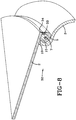
- FIG 8 shows yet another embodiment of the present invention.
- This embodiment of the invention includes a top plate 2 and a clamp ring 5.
- This embodiment also includes the flexible member 3 and the piston 4 as were used in the conventional state of the art air spring 1.
- the clamp ring 5 includes a clamp ring labyrinth 33 which is adapted to intermesh with a top plate labyrinth 34 of the top plate 2.
- the clamp ring includes a compression hook 15 which is adapted to compress the upper portion of the flexible member 10 against the top plate 2 when the three components are assembled together. The compression of the upper portion of the flexible member 10 against the top plate 2 creates an air tight seal.
- the upper portion of the flexible member 10 is affixed between the top plate 2 and the compression hook 15.
- the upper portion of the flexible member 10 includes a retention bead 7.
- the retention bead 7 improves the retention of the upper portion of the flexible member 10 in position between the top plate 2 and the compression hook 15.
- the retention bead 7 may consist of steel, polymeric fibers, or any other material which has a greater modulus of elasticity than the material used for the flexible member 3.
- Assembly of the labyrinth air spring 32 of this embodiment of the invention is accomplished by fusing the clamp ring labyrinth 33 to the top plate labyrinth 34, such as by use of an adhesive.
- the upper portion of the flexible member 10 is positioned over the compression hook 15.
- the first two steps of the assembly process may be interchanged.
- the top plate 2 is then positioned over the upper portion of the flexible member 10 so that the top plate labyrinth 34 and the clamp ring labyrinth 33 are aligned.
- the top plate 2 can then be pressed toward the compression hook 15 to compress the upper portion of the flexible member 10.
- the structural components of the present invention may consist of metallic or polymeric materials.
- the structural components of the present invention may consist of ferrous or non-ferrous metals including steel, stainless steel, aluminum, magnesium, zinc and cast iron.
- the structural components of the present invention which consist of metallic materials may be coated for increased corrosion resistance. Because all of the embodiments of the present invention, except for the clamp ring 5 of the deformed ring air spring 18, are formed in their final structure before assembly of the components; the structural components of the present invention do not have the issue of damage to the anti-corrosive coating.
- the anti-corrosive coating may include zinc coating, oxide coating, paint, powder coating or any other coating known in the art.
- the structural components of the present invention will preferably be injection molded from a resilient polymeric material, such as a thermoplastic and particularly fiber filled thermoplastics.
- the polymeric material utilized can be a polycarbonate, a polyester, a polyolefin, or a polyamide.
- polyolefins that can be used include fiber filled low density polyethylene, fiber filled linear low density polyethylene, fiber filled high density polyethylene, and fiber filled polypropylene.
- polyesters that can be used include polyethylene terephthalate, polyethylene terephthalate copolymers containing up to about 5 weight percent isophthalic acid, and polyethylene napthalate.
- the resilient material will more preferably be a fiber filled polyamide.
- the fiber will preferably be glass fibers and will typically be loaded at a level of 15 to 50 weight percent.
- the fiber will preferably be loaded at a level of 25 to 40 weight percent.
- the fiber will more preferably be loaded at a level of 30 to 35 weight percent.
- Some representative examples ofpolyamides that can be utilized include nylon-6, nylon-11, nylon-12, nylon-6,6, nylon-4,6, nylon-6,10, and nylon-6,12.
- Such nylon materials will preferably be filled with a glass fiber.
- Highly preferred materials include nylon-6,6 which is filled with long glass fibers (commercially available as CELSTRAN), and short fiber reinforced thermoplastic (commercially available as ZYTEL).
- the tensile strength of the material should be within the range of 1965 to 3165 kg/cm 2 (28,000 to 45,000 psi). It will preferably also have a flex strength in the range of 2810 to 4220 kg/cm 2 (40,000 to 60,000 psi) and notched izod strength of 0.117-0.703 N-m/mm (2.0 to 12.0 ft-lb/in).
Landscapes
- Engineering & Computer Science (AREA)
- General Engineering & Computer Science (AREA)
- Mechanical Engineering (AREA)
- Fluid-Damping Devices (AREA)
Claims (11)
- Suspension pneumatique, caractérisée en ce qu'elle est constituée d'un piston (4), d'une plaque supérieure (2), d'une bague de serrage (5) et d'un élément flexible (3) qui est fixé sur le piston (4) et la plaque supérieure (2), dans laquelle le piston (4), la plaque supérieure (2) et l'élément flexible (3) définissent une chambre pouvant être mise sous pression (14), dans laquelle la bague de serrage (5) fixe une partie supérieure de l'élément flexible (10) sur la plaque supérieure (2) et retient l'élément flexible (3) en contact étanche à l'air avec la plaque supérieure (2), caractérisée en ce que l'élément flexible (3) comprend un talon de rétention (7) au niveau d'une partie supérieure de l'élément flexible (10) et en ce que la bague de serrage (5) comprend un crochet de compression (15) conçu pour presser l'élément flexible (3) contre la plaque supérieure (2) lorsque les trois composants sont assemblés ensemble.
- Suspension pneumatique selon la revendication 1, caractérisée en ce qu'elle est en outre constituée d'un anneau de retenue (6), dans laquelle l'anneau de retenue (6) est fixé à la bague de serrage (5), dans laquelle la bague de serrage (5) fixe l'anneau de retenue (6) sur la plaque supérieure (2), et dans laquelle la plaque supérieure (2) est fixée entre l'anneau de retenue (6) et l'élément flexible (3).
- Suspension pneumatique selon la revendication 1, caractérisée en ce qu'une partie de la bague de serrage (5) est déformée par-dessus la plaque supérieure (2) pour retenir l'élément flexible (3) en contact étanche à l'air permanent avec l'élément supérieur, et dans laquelle la plaque supérieure (2) est fixée entre la partie supérieure de l'élément flexible (3) et la partie déformée (20) de la bague de serrage (5).
- Suspension pneumatique selon la revendication 1, caractérisée en ce que la bague de serrage (5) est constituée d'une pluralité de taquets flexibles (23), et dans laquelle la plaque supérieure (2) est fixée entre la partie supérieure de l'élément flexible (10) et la pluralité de taquets flexibles (23).
- Suspension pneumatique selon la revendication 4, caractérisée en ce qu'elle est en outre constituée d'une bague de blocage, dans laquelle la bague de blocage (25) est fixée autour de la pluralité de taquets flexibles (23) .
- Suspension pneumatique selon la revendication 5, caractérisée en ce que la bague de serrage (5) s'élargit autour de la circonférence externe de la plaque supérieure (2).
- Suspension pneumatique selon la revendication 6, caractérisée en ce que la plaque supérieure (2) inclut une pluralité de ports de réception de taquets (26) dans lesquels la pluralité de taquets flexibles (23) de la bague de serrage (5) sont bloqués.
- Suspension pneumatique selon la revendication 1, caractérisée en ce qu'elle est en outre constituée par une bague de retenue (28), dans laquelle la bague de serrage (5) comprend une pluralité de taquets (29) de bague de serrage, dans laquelle la plaque supérieure (2) comprend une pluralité de taquets (30) de plaque supérieure, dans laquelle les taquets (29) de bague de serrage s'entrelacent avec les taquets (30) de plaque supérieure, dans laquelle les taquets (29) de bague de serrage et les taquets (30) de plaque supérieure forment ensemble un canal (31) qui est conçu pour loger la bague de retenue (28), et dans laquelle la position relative entre la bague de serrage (5) et la plaque supérieure (2) est sensiblement fixée par la bague de retenue (28).
- Suspension pneumatique selon la revendication 1, caractérisée en ce que la bague de serrage (5) comprend un labyrinthe (33) de bague de serrage, dans laquelle la plaque supérieure (2) comprend un labyrinthe (34) de plaque supérieure, dans laquelle le labyrinthe (33) de bague de serrage s'engrène avec le labyrinthe (34) de plaque supérieure, et dans laquelle le labyrinthe de bague de serrage est fusionné avec le labyrinthe de la plaque supérieure (2).
- Suspension pneumatique selon la revendication 9, caractérisée en ce que le labyrinthe (33) est fusionné avec le labyrinthe (34) de plaque supérieure par un adhésif.
- Suspension pneumatique selon l'une quelconque des revendications précédentes, caractérisée en ce que la plaque supérieure (2) et la bague de serrage (5) sont constituées d'un polyamide de charge de verre.
Applications Claiming Priority (1)
| Application Number | Priority Date | Filing Date | Title |
|---|---|---|---|
| US201361774707P | 2013-03-08 | 2013-03-08 |
Publications (3)
| Publication Number | Publication Date |
|---|---|
| EP2775162A2 EP2775162A2 (fr) | 2014-09-10 |
| EP2775162A3 EP2775162A3 (fr) | 2015-09-23 |
| EP2775162B1 true EP2775162B1 (fr) | 2019-10-30 |
Family
ID=50238167
Family Applications (1)
| Application Number | Title | Priority Date | Filing Date |
|---|---|---|---|
| EP14157606.6A Active EP2775162B1 (fr) | 2013-03-08 | 2014-03-04 | Plaque de talon composite et suspension pneumatique l'utilisant |
Country Status (2)
| Country | Link |
|---|---|
| US (2) | US9388876B2 (fr) |
| EP (1) | EP2775162B1 (fr) |
Families Citing this family (17)
| Publication number | Priority date | Publication date | Assignee | Title |
|---|---|---|---|---|
| EP2775162B1 (fr) * | 2013-03-08 | 2019-10-30 | ContiTech USA, Inc. | Plaque de talon composite et suspension pneumatique l'utilisant |
| DE102015100281A1 (de) | 2015-01-09 | 2016-07-14 | Trelleborgvibracoustic Gmbh | Verbundbauteil sowie Luftfederkomponente mit einem derartigen Verbundbauteil |
| US10752070B2 (en) * | 2015-07-01 | 2020-08-25 | Firestone Industrial Products Company, Llc | Clamping plates and gas spring assemblies as well as suspension systems and methods including same |
| EP3165786B1 (fr) * | 2015-11-03 | 2023-08-23 | ContiTech Luftfedersysteme GmbH | Piston à ressort pneumatique |
| US10197126B2 (en) | 2016-04-21 | 2019-02-05 | Firestone Industrial Products Company, Llc | Gas spring end members as well as gas spring assemblies, suspension systems and methods |
| US10618366B2 (en) | 2016-07-08 | 2020-04-14 | Continental Automotive Systems, Inc. | Vehicle air strut with twist lock closure cover |
| DE102017202094A1 (de) * | 2017-02-09 | 2018-08-09 | Contitech Luftfedersysteme Gmbh | Luftfeder mit einem Kunststoffdeckel |
| DE102017209199A1 (de) * | 2017-05-31 | 2018-12-06 | Contitech Luftfedersysteme Gmbh | Luftfeder |
| DE102017213700A1 (de) * | 2017-08-07 | 2019-02-07 | Contitech Luftfedersysteme Gmbh | Abdichtungsanordnung |
| DE102017222588A1 (de) * | 2017-12-13 | 2019-06-13 | Contitech Luftfedersysteme Gmbh | Luftfeder |
| JP7088799B2 (ja) * | 2018-09-27 | 2022-06-21 | ニッタ化工品株式会社 | 空気ばね及びその組立方法 |
| USD913081S1 (en) | 2019-05-29 | 2021-03-16 | The Boeing Company | Structural spacer member |
| US11059586B2 (en) * | 2019-05-29 | 2021-07-13 | The Boeing Company | Structural spacer members |
| JP7206158B2 (ja) * | 2019-06-18 | 2023-01-17 | 株式会社プロスパイラ | 空気ばね |
| WO2021142190A1 (fr) * | 2020-01-10 | 2021-07-15 | Infinity Engineered Products, Llc | Ressort pneumatique comportant des pièces composites |
| EP4008572B1 (fr) * | 2020-12-02 | 2023-09-06 | ContiTech AG | Ressort pneumatique |
| US20230191865A1 (en) * | 2021-12-20 | 2023-06-22 | Continental Automotive Systems, Inc. | Airspring gaiter with sliding joint |
Family Cites Families (24)
| Publication number | Priority date | Publication date | Assignee | Title |
|---|---|---|---|---|
| US894117A (en) * | 1907-06-24 | 1908-07-21 | Frank M Thompson | Pneumatic suspension means. |
| GB779809A (en) * | 1954-12-14 | 1957-07-24 | Continental Gummi Werke Ag | Improvements in or relating to pneumatic shock absorbers |
| DE1132010B (de) * | 1956-05-28 | 1962-06-20 | Daimler Benz Ag | Anordnung der offenen Enden von Faltenbaelgen fuer Kraftfahrzeug-Luftfedern an ihrenHalteteilen |
| GB873348A (en) * | 1957-01-17 | 1961-07-26 | Dunlop Rubber Co | Flexible bellows and diaphragms |
| US2922637A (en) * | 1957-05-29 | 1960-01-26 | Gen Motors Corp | Air spring bellows |
| GB907555A (en) * | 1958-03-06 | 1962-10-10 | Dunlop Rubber Co | Fluid spring assembly |
| GB1001515A (en) * | 1961-06-27 | 1965-08-18 | Dunlop Rubber Co | Improvements in fluid springs |
| DE1430597A1 (de) * | 1964-03-21 | 1969-04-03 | Bosch Gmbh Robert | Luftfederelemente,insbesondere fuer Fahrzeuge |
| FR2117118A5 (fr) * | 1970-12-07 | 1972-07-21 | Kaessbohrer Fahrzeug Karl | |
| US4787607A (en) * | 1986-09-24 | 1988-11-29 | The Firestone Tire & Rubber Company | Air spring having internal sealing band and method of installing same |
| US4793598A (en) * | 1986-09-24 | 1988-12-27 | The Firestone Tire & Rubber Company | Air spring having internal sealing band and method of installing same |
| US4784376A (en) | 1987-06-17 | 1988-11-15 | The Firestone Tire & Rubber Company | End cap assembly for air spring |
| US4787606A (en) * | 1987-06-17 | 1988-11-29 | The Firestone Tire & Rubber Company | Beadless air spring |
| US4946144A (en) * | 1989-03-30 | 1990-08-07 | Bridgestone/Firestone, Inc. | External clamping band for air spring |
| DE4006480A1 (de) * | 1990-03-02 | 1991-09-05 | Continental Ag | Rollbalg-luftfeder mit einem schlauchrollbalg aus elastomerem werkstoff |
| US6926264B1 (en) | 1999-05-28 | 2005-08-09 | The Goodyear Tire & Rubber Company | Air spring upper retainer |
| EP1222409B1 (fr) | 1999-10-22 | 2004-12-22 | BFS Diversified Products, LLC | Support et plaque de montage d'extremite monobloc pour ressort pneumatique |
| DE10163818B4 (de) * | 2001-12-22 | 2020-08-20 | Contitech Luftfedersysteme Gmbh | Schlauchrollbalg-Feder |
| DE102004030335A1 (de) | 2004-06-23 | 2006-01-19 | Contitech Luftfedersysteme Gmbh | Luftfeder mit einem Abrollkolben und einem Rollbalg mit mindestens einem anvulkanisierten Befestigungsteil |
| US7325794B2 (en) * | 2005-06-06 | 2008-02-05 | Bfs Diversified Products, Llc | Air spring assembly and method |
| US8800974B2 (en) * | 2006-11-14 | 2014-08-12 | Firestone Industrial Products Company, Llc | Air spring sleeve |
| US8141854B2 (en) * | 2007-04-09 | 2012-03-27 | Firestone Industrial Products Company, Llc | Gas spring assembly and method |
| JP2012122558A (ja) * | 2010-12-09 | 2012-06-28 | Toyo Tire & Rubber Co Ltd | 空気ばね及びその製造方法 |
| EP2775162B1 (fr) * | 2013-03-08 | 2019-10-30 | ContiTech USA, Inc. | Plaque de talon composite et suspension pneumatique l'utilisant |
-
2014
- 2014-03-04 EP EP14157606.6A patent/EP2775162B1/fr active Active
- 2014-03-07 US US14/200,150 patent/US9388876B2/en active Active
-
2016
- 2016-06-15 US US15/183,586 patent/US10690208B2/en active Active
Non-Patent Citations (1)
| Title |
|---|
| None * |
Also Published As
| Publication number | Publication date |
|---|---|
| EP2775162A3 (fr) | 2015-09-23 |
| EP2775162A2 (fr) | 2014-09-10 |
| US10690208B2 (en) | 2020-06-23 |
| US20170023085A1 (en) | 2017-01-26 |
| US9388876B2 (en) | 2016-07-12 |
| US20140252702A1 (en) | 2014-09-11 |
Similar Documents
| Publication | Publication Date | Title |
|---|---|---|
| EP2775162B1 (fr) | Plaque de talon composite et suspension pneumatique l'utilisant | |
| US10451136B2 (en) | High creep resistance plastic material reinforced rings | |
| EP3156258B1 (fr) | Pneu | |
| US6234460B1 (en) | Push-on air spring bumper | |
| EP2031267B1 (fr) | Ressort à gaz et son procédé de fabrication | |
| US7258330B2 (en) | Air spring device | |
| EP1425521A2 (fr) | Mecanisme de direction a pignon et cremaillere realise sous forme unitaire | |
| US11707959B2 (en) | Air spring strut with a plastics air spring cover | |
| EP1530690B1 (fr) | Manchon pour ressort pneumatique | |
| US20090278289A1 (en) | Cover Assembly for a Vehicle Air Spring | |
| WO2011034927A2 (fr) | Piston à ressort à gaz, ensemble ressort à gaz et procédé | |
| EP1190183A1 (fr) | Butee elastique de suspension pneumatique utilisant une combinaison de matieres | |
| EP0927631A1 (fr) | Diaphragme et accumulateur utilisant ceci | |
| US20050236749A1 (en) | Cover assembly for a pneumatic spring | |
| US20030094740A1 (en) | Air-spring system | |
| EP3165786B1 (fr) | Piston à ressort pneumatique | |
| EP1179146B1 (fr) | Ressort pneumatique et dispositif de retenue pour ressort pneumatique | |
| US8733743B2 (en) | Gas spring piston, gas spring assembly and method | |
| US10857874B2 (en) | Tank having a stiffening device | |
| JP5769654B2 (ja) | バンプストッパ | |
| US20160121681A1 (en) | Shaped rubber flexible member | |
| EP0264573B1 (fr) | Ressort pneumatique avec anneau d'étanchéité interne et son procédé de montage | |
| EP3604003B1 (fr) | Butée composite à encliqueter sur piston composite | |
| EP2669544A1 (fr) | Pare-chocs d'amortissement pour suspensions de véhicules à moteur | |
| EP2647871A1 (fr) | Ressort pneumatique |
Legal Events
| Date | Code | Title | Description |
|---|---|---|---|
| PUAI | Public reference made under article 153(3) epc to a published international application that has entered the european phase |
Free format text: ORIGINAL CODE: 0009012 |
|
| 17P | Request for examination filed |
Effective date: 20140304 |
|
| AK | Designated contracting states |
Kind code of ref document: A2 Designated state(s): AL AT BE BG CH CY CZ DE DK EE ES FI FR GB GR HR HU IE IS IT LI LT LU LV MC MK MT NL NO PL PT RO RS SE SI SK SM TR |
|
| AX | Request for extension of the european patent |
Extension state: BA ME |
|
| PUAL | Search report despatched |
Free format text: ORIGINAL CODE: 0009013 |
|
| AK | Designated contracting states |
Kind code of ref document: A3 Designated state(s): AL AT BE BG CH CY CZ DE DK EE ES FI FR GB GR HR HU IE IS IT LI LT LU LV MC MK MT NL NO PL PT RO RS SE SI SK SM TR |
|
| AX | Request for extension of the european patent |
Extension state: BA ME |
|
| RIC1 | Information provided on ipc code assigned before grant |
Ipc: B60G 11/27 20060101ALI20150819BHEP Ipc: F16F 9/04 20060101AFI20150819BHEP |
|
| R17P | Request for examination filed (corrected) |
Effective date: 20160322 |
|
| RBV | Designated contracting states (corrected) |
Designated state(s): AL AT BE BG CH CY CZ DE DK EE ES FI FR GB GR HR HU IE IS IT LI LT LU LV MC MK MT NL NO PL PT RO RS SE SI SK SM TR |
|
| RAP1 | Party data changed (applicant data changed or rights of an application transferred) |
Owner name: CONTITECH USA, INC. |
|
| RAP1 | Party data changed (applicant data changed or rights of an application transferred) |
Owner name: CONTITECH USA, INC. |
|
| STAA | Information on the status of an ep patent application or granted ep patent |
Free format text: STATUS: EXAMINATION IS IN PROGRESS |
|
| 17Q | First examination report despatched |
Effective date: 20180529 |
|
| GRAP | Despatch of communication of intention to grant a patent |
Free format text: ORIGINAL CODE: EPIDOSNIGR1 |
|
| STAA | Information on the status of an ep patent application or granted ep patent |
Free format text: STATUS: GRANT OF PATENT IS INTENDED |
|
| RIN1 | Information on inventor provided before grant (corrected) |
Inventor name: PALKY, DAVID A. Inventor name: TROWBRIDGE, MARK G. Inventor name: MAGUIRE, DAVID J. |
|
| INTG | Intention to grant announced |
Effective date: 20190715 |
|
| GRAS | Grant fee paid |
Free format text: ORIGINAL CODE: EPIDOSNIGR3 |
|
| GRAA | (expected) grant |
Free format text: ORIGINAL CODE: 0009210 |
|
| STAA | Information on the status of an ep patent application or granted ep patent |
Free format text: STATUS: THE PATENT HAS BEEN GRANTED |
|
| AK | Designated contracting states |
Kind code of ref document: B1 Designated state(s): AL AT BE BG CH CY CZ DE DK EE ES FI FR GB GR HR HU IE IS IT LI LT LU LV MC MK MT NL NO PL PT RO RS SE SI SK SM TR |
|
| REG | Reference to a national code |
Ref country code: GB Ref legal event code: FG4D |
|
| REG | Reference to a national code |
Ref country code: CH Ref legal event code: EP |
|
| REG | Reference to a national code |
Ref country code: AT Ref legal event code: REF Ref document number: 1196475 Country of ref document: AT Kind code of ref document: T Effective date: 20191115 |
|
| REG | Reference to a national code |
Ref country code: DE Ref legal event code: R096 Ref document number: 602014055832 Country of ref document: DE |
|
| REG | Reference to a national code |
Ref country code: IE Ref legal event code: FG4D |
|
| REG | Reference to a national code |
Ref country code: LT Ref legal event code: MG4D |
|
| PG25 | Lapsed in a contracting state [announced via postgrant information from national office to epo] |
Ref country code: GR Free format text: LAPSE BECAUSE OF FAILURE TO SUBMIT A TRANSLATION OF THE DESCRIPTION OR TO PAY THE FEE WITHIN THE PRESCRIBED TIME-LIMIT Effective date: 20200131 Ref country code: PL Free format text: LAPSE BECAUSE OF FAILURE TO SUBMIT A TRANSLATION OF THE DESCRIPTION OR TO PAY THE FEE WITHIN THE PRESCRIBED TIME-LIMIT Effective date: 20191030 Ref country code: NO Free format text: LAPSE BECAUSE OF FAILURE TO SUBMIT A TRANSLATION OF THE DESCRIPTION OR TO PAY THE FEE WITHIN THE PRESCRIBED TIME-LIMIT Effective date: 20200130 Ref country code: FI Free format text: LAPSE BECAUSE OF FAILURE TO SUBMIT A TRANSLATION OF THE DESCRIPTION OR TO PAY THE FEE WITHIN THE PRESCRIBED TIME-LIMIT Effective date: 20191030 Ref country code: LV Free format text: LAPSE BECAUSE OF FAILURE TO SUBMIT A TRANSLATION OF THE DESCRIPTION OR TO PAY THE FEE WITHIN THE PRESCRIBED TIME-LIMIT Effective date: 20191030 Ref country code: SE Free format text: LAPSE BECAUSE OF FAILURE TO SUBMIT A TRANSLATION OF THE DESCRIPTION OR TO PAY THE FEE WITHIN THE PRESCRIBED TIME-LIMIT Effective date: 20191030 Ref country code: BG Free format text: LAPSE BECAUSE OF FAILURE TO SUBMIT A TRANSLATION OF THE DESCRIPTION OR TO PAY THE FEE WITHIN THE PRESCRIBED TIME-LIMIT Effective date: 20200130 Ref country code: PT Free format text: LAPSE BECAUSE OF FAILURE TO SUBMIT A TRANSLATION OF THE DESCRIPTION OR TO PAY THE FEE WITHIN THE PRESCRIBED TIME-LIMIT Effective date: 20200302 Ref country code: ES Free format text: LAPSE BECAUSE OF FAILURE TO SUBMIT A TRANSLATION OF THE DESCRIPTION OR TO PAY THE FEE WITHIN THE PRESCRIBED TIME-LIMIT Effective date: 20191030 Ref country code: NL Free format text: LAPSE BECAUSE OF FAILURE TO SUBMIT A TRANSLATION OF THE DESCRIPTION OR TO PAY THE FEE WITHIN THE PRESCRIBED TIME-LIMIT Effective date: 20191030 Ref country code: LT Free format text: LAPSE BECAUSE OF FAILURE TO SUBMIT A TRANSLATION OF THE DESCRIPTION OR TO PAY THE FEE WITHIN THE PRESCRIBED TIME-LIMIT Effective date: 20191030 |
|
| REG | Reference to a national code |
Ref country code: NL Ref legal event code: MP Effective date: 20191030 |
|
| PG25 | Lapsed in a contracting state [announced via postgrant information from national office to epo] |
Ref country code: HR Free format text: LAPSE BECAUSE OF FAILURE TO SUBMIT A TRANSLATION OF THE DESCRIPTION OR TO PAY THE FEE WITHIN THE PRESCRIBED TIME-LIMIT Effective date: 20191030 Ref country code: RS Free format text: LAPSE BECAUSE OF FAILURE TO SUBMIT A TRANSLATION OF THE DESCRIPTION OR TO PAY THE FEE WITHIN THE PRESCRIBED TIME-LIMIT Effective date: 20191030 Ref country code: IS Free format text: LAPSE BECAUSE OF FAILURE TO SUBMIT A TRANSLATION OF THE DESCRIPTION OR TO PAY THE FEE WITHIN THE PRESCRIBED TIME-LIMIT Effective date: 20200229 |
|
| PG25 | Lapsed in a contracting state [announced via postgrant information from national office to epo] |
Ref country code: AL Free format text: LAPSE BECAUSE OF FAILURE TO SUBMIT A TRANSLATION OF THE DESCRIPTION OR TO PAY THE FEE WITHIN THE PRESCRIBED TIME-LIMIT Effective date: 20191030 |
|
| PG25 | Lapsed in a contracting state [announced via postgrant information from national office to epo] |
Ref country code: CZ Free format text: LAPSE BECAUSE OF FAILURE TO SUBMIT A TRANSLATION OF THE DESCRIPTION OR TO PAY THE FEE WITHIN THE PRESCRIBED TIME-LIMIT Effective date: 20191030 Ref country code: RO Free format text: LAPSE BECAUSE OF FAILURE TO SUBMIT A TRANSLATION OF THE DESCRIPTION OR TO PAY THE FEE WITHIN THE PRESCRIBED TIME-LIMIT Effective date: 20191030 Ref country code: EE Free format text: LAPSE BECAUSE OF FAILURE TO SUBMIT A TRANSLATION OF THE DESCRIPTION OR TO PAY THE FEE WITHIN THE PRESCRIBED TIME-LIMIT Effective date: 20191030 Ref country code: DK Free format text: LAPSE BECAUSE OF FAILURE TO SUBMIT A TRANSLATION OF THE DESCRIPTION OR TO PAY THE FEE WITHIN THE PRESCRIBED TIME-LIMIT Effective date: 20191030 |
|
| REG | Reference to a national code |
Ref country code: DE Ref legal event code: R097 Ref document number: 602014055832 Country of ref document: DE |
|
| REG | Reference to a national code |
Ref country code: AT Ref legal event code: MK05 Ref document number: 1196475 Country of ref document: AT Kind code of ref document: T Effective date: 20191030 |
|
| PG25 | Lapsed in a contracting state [announced via postgrant information from national office to epo] |
Ref country code: IT Free format text: LAPSE BECAUSE OF FAILURE TO SUBMIT A TRANSLATION OF THE DESCRIPTION OR TO PAY THE FEE WITHIN THE PRESCRIBED TIME-LIMIT Effective date: 20191030 Ref country code: SM Free format text: LAPSE BECAUSE OF FAILURE TO SUBMIT A TRANSLATION OF THE DESCRIPTION OR TO PAY THE FEE WITHIN THE PRESCRIBED TIME-LIMIT Effective date: 20191030 Ref country code: SK Free format text: LAPSE BECAUSE OF FAILURE TO SUBMIT A TRANSLATION OF THE DESCRIPTION OR TO PAY THE FEE WITHIN THE PRESCRIBED TIME-LIMIT Effective date: 20191030 |
|
| PLBE | No opposition filed within time limit |
Free format text: ORIGINAL CODE: 0009261 |
|
| STAA | Information on the status of an ep patent application or granted ep patent |
Free format text: STATUS: NO OPPOSITION FILED WITHIN TIME LIMIT |
|
| 26N | No opposition filed |
Effective date: 20200731 |
|
| PG25 | Lapsed in a contracting state [announced via postgrant information from national office to epo] |
Ref country code: MC Free format text: LAPSE BECAUSE OF FAILURE TO SUBMIT A TRANSLATION OF THE DESCRIPTION OR TO PAY THE FEE WITHIN THE PRESCRIBED TIME-LIMIT Effective date: 20191030 |
|
| REG | Reference to a national code |
Ref country code: CH Ref legal event code: PL |
|
| PG25 | Lapsed in a contracting state [announced via postgrant information from national office to epo] |
Ref country code: AT Free format text: LAPSE BECAUSE OF FAILURE TO SUBMIT A TRANSLATION OF THE DESCRIPTION OR TO PAY THE FEE WITHIN THE PRESCRIBED TIME-LIMIT Effective date: 20191030 Ref country code: SI Free format text: LAPSE BECAUSE OF FAILURE TO SUBMIT A TRANSLATION OF THE DESCRIPTION OR TO PAY THE FEE WITHIN THE PRESCRIBED TIME-LIMIT Effective date: 20191030 |
|
| REG | Reference to a national code |
Ref country code: BE Ref legal event code: MM Effective date: 20200331 |
|
| PG25 | Lapsed in a contracting state [announced via postgrant information from national office to epo] |
Ref country code: LU Free format text: LAPSE BECAUSE OF NON-PAYMENT OF DUE FEES Effective date: 20200304 |
|
| PG25 | Lapsed in a contracting state [announced via postgrant information from national office to epo] |
Ref country code: LI Free format text: LAPSE BECAUSE OF NON-PAYMENT OF DUE FEES Effective date: 20200331 Ref country code: IE Free format text: LAPSE BECAUSE OF NON-PAYMENT OF DUE FEES Effective date: 20200304 Ref country code: CH Free format text: LAPSE BECAUSE OF NON-PAYMENT OF DUE FEES Effective date: 20200331 |
|
| PG25 | Lapsed in a contracting state [announced via postgrant information from national office to epo] |
Ref country code: BE Free format text: LAPSE BECAUSE OF NON-PAYMENT OF DUE FEES Effective date: 20200331 |
|
| PG25 | Lapsed in a contracting state [announced via postgrant information from national office to epo] |
Ref country code: TR Free format text: LAPSE BECAUSE OF FAILURE TO SUBMIT A TRANSLATION OF THE DESCRIPTION OR TO PAY THE FEE WITHIN THE PRESCRIBED TIME-LIMIT Effective date: 20191030 Ref country code: MT Free format text: LAPSE BECAUSE OF FAILURE TO SUBMIT A TRANSLATION OF THE DESCRIPTION OR TO PAY THE FEE WITHIN THE PRESCRIBED TIME-LIMIT Effective date: 20191030 Ref country code: CY Free format text: LAPSE BECAUSE OF FAILURE TO SUBMIT A TRANSLATION OF THE DESCRIPTION OR TO PAY THE FEE WITHIN THE PRESCRIBED TIME-LIMIT Effective date: 20191030 |
|
| PG25 | Lapsed in a contracting state [announced via postgrant information from national office to epo] |
Ref country code: MK Free format text: LAPSE BECAUSE OF FAILURE TO SUBMIT A TRANSLATION OF THE DESCRIPTION OR TO PAY THE FEE WITHIN THE PRESCRIBED TIME-LIMIT Effective date: 20191030 |
|
| PGFP | Annual fee paid to national office [announced via postgrant information from national office to epo] |
Ref country code: GB Payment date: 20260324 Year of fee payment: 13 |
|
| PGFP | Annual fee paid to national office [announced via postgrant information from national office to epo] |
Ref country code: DE Payment date: 20260331 Year of fee payment: 13 |
|
| PGFP | Annual fee paid to national office [announced via postgrant information from national office to epo] |
Ref country code: FR Payment date: 20260320 Year of fee payment: 13 |