EP2775222A2 - Radiateur, et procédé pour le contrôler - Google Patents
Radiateur, et procédé pour le contrôler Download PDFInfo
- Publication number
- EP2775222A2 EP2775222A2 EP14157994.6A EP14157994A EP2775222A2 EP 2775222 A2 EP2775222 A2 EP 2775222A2 EP 14157994 A EP14157994 A EP 14157994A EP 2775222 A2 EP2775222 A2 EP 2775222A2
- Authority
- EP
- European Patent Office
- Prior art keywords
- radiator
- valve fitting
- valve
- fitting
- heat transfer
- Prior art date
- Legal status (The legal status is an assumption and is not a legal conclusion. Google has not performed a legal analysis and makes no representation as to the accuracy of the status listed.)
- Withdrawn
Links
- 238000000034 method Methods 0.000 title claims description 9
- 239000007788 liquid Substances 0.000 claims abstract description 34
- 238000012546 transfer Methods 0.000 claims abstract description 22
- 238000007599 discharging Methods 0.000 claims abstract description 4
- 230000005855 radiation Effects 0.000 description 2
- 229910001369 Brass Inorganic materials 0.000 description 1
- 239000010951 brass Substances 0.000 description 1
- 238000004891 communication Methods 0.000 description 1
- 230000001419 dependent effect Effects 0.000 description 1
- 238000013461 design Methods 0.000 description 1
- 238000005516 engineering process Methods 0.000 description 1
- 238000004519 manufacturing process Methods 0.000 description 1
- 238000012544 monitoring process Methods 0.000 description 1
- 238000005457 optimization Methods 0.000 description 1
Images

Classifications
-
- F—MECHANICAL ENGINEERING; LIGHTING; HEATING; WEAPONS; BLASTING
- F24—HEATING; RANGES; VENTILATING
- F24D—DOMESTIC- OR SPACE-HEATING SYSTEMS, e.g. CENTRAL HEATING SYSTEMS; DOMESTIC HOT-WATER SUPPLY SYSTEMS; ELEMENTS OR COMPONENTS THEREFOR
- F24D19/00—Details
- F24D19/0002—Means for connecting central heating radiators to circulation pipes
- F24D19/0073—Means for changing the flow of the fluid inside a radiator
-
- F—MECHANICAL ENGINEERING; LIGHTING; HEATING; WEAPONS; BLASTING
- F16—ENGINEERING ELEMENTS AND UNITS; GENERAL MEASURES FOR PRODUCING AND MAINTAINING EFFECTIVE FUNCTIONING OF MACHINES OR INSTALLATIONS; THERMAL INSULATION IN GENERAL
- F16K—VALVES; TAPS; COCKS; ACTUATING-FLOATS; DEVICES FOR VENTING OR AERATING
- F16K27/00—Construction of housing; Use of materials therefor
- F16K27/02—Construction of housing; Use of materials therefor of lift valves
- F16K27/029—Electromagnetically actuated valves
-
- F—MECHANICAL ENGINEERING; LIGHTING; HEATING; WEAPONS; BLASTING
- F16—ENGINEERING ELEMENTS AND UNITS; GENERAL MEASURES FOR PRODUCING AND MAINTAINING EFFECTIVE FUNCTIONING OF MACHINES OR INSTALLATIONS; THERMAL INSULATION IN GENERAL
- F16K—VALVES; TAPS; COCKS; ACTUATING-FLOATS; DEVICES FOR VENTING OR AERATING
- F16K27/00—Construction of housing; Use of materials therefor
- F16K27/06—Construction of housing; Use of materials therefor of taps or cocks
- F16K27/065—Construction of housing; Use of materials therefor of taps or cocks with cylindrical plugs
-
- F—MECHANICAL ENGINEERING; LIGHTING; HEATING; WEAPONS; BLASTING
- F16—ENGINEERING ELEMENTS AND UNITS; GENERAL MEASURES FOR PRODUCING AND MAINTAINING EFFECTIVE FUNCTIONING OF MACHINES OR INSTALLATIONS; THERMAL INSULATION IN GENERAL
- F16K—VALVES; TAPS; COCKS; ACTUATING-FLOATS; DEVICES FOR VENTING OR AERATING
- F16K31/00—Actuating devices; Operating means; Releasing devices
- F16K31/02—Actuating devices; Operating means; Releasing devices electric; magnetic
- F16K31/06—Actuating devices; Operating means; Releasing devices electric; magnetic using a magnet, e.g. diaphragm valves, cutting off by means of a liquid
- F16K31/0644—One-way valve
- F16K31/0655—Lift valves
-
- F—MECHANICAL ENGINEERING; LIGHTING; HEATING; WEAPONS; BLASTING
- F16—ENGINEERING ELEMENTS AND UNITS; GENERAL MEASURES FOR PRODUCING AND MAINTAINING EFFECTIVE FUNCTIONING OF MACHINES OR INSTALLATIONS; THERMAL INSULATION IN GENERAL
- F16K—VALVES; TAPS; COCKS; ACTUATING-FLOATS; DEVICES FOR VENTING OR AERATING
- F16K5/00—Plug valves; Taps or cocks comprising only cut-off apparatus having at least one of the sealing faces shaped as a more or less complete surface of a solid of revolution, the opening and closing movement being predominantly rotary
- F16K5/04—Plug valves; Taps or cocks comprising only cut-off apparatus having at least one of the sealing faces shaped as a more or less complete surface of a solid of revolution, the opening and closing movement being predominantly rotary with plugs having cylindrical surfaces; Packings therefor
- F16K5/0414—Plug channel at 90 degrees to the inlet
-
- F—MECHANICAL ENGINEERING; LIGHTING; HEATING; WEAPONS; BLASTING
- F24—HEATING; RANGES; VENTILATING
- F24D—DOMESTIC- OR SPACE-HEATING SYSTEMS, e.g. CENTRAL HEATING SYSTEMS; DOMESTIC HOT-WATER SUPPLY SYSTEMS; ELEMENTS OR COMPONENTS THEREFOR
- F24D19/00—Details
- F24D19/0002—Means for connecting central heating radiators to circulation pipes
- F24D19/0004—In a one pipe system
- F24D19/0007—Comprising regulation means
-
- F—MECHANICAL ENGINEERING; LIGHTING; HEATING; WEAPONS; BLASTING
- F24—HEATING; RANGES; VENTILATING
- F24D—DOMESTIC- OR SPACE-HEATING SYSTEMS, e.g. CENTRAL HEATING SYSTEMS; DOMESTIC HOT-WATER SUPPLY SYSTEMS; ELEMENTS OR COMPONENTS THEREFOR
- F24D19/00—Details
- F24D19/0002—Means for connecting central heating radiators to circulation pipes
- F24D19/0009—In a two pipe system
- F24D19/0012—Comprising regulation means
-
- F—MECHANICAL ENGINEERING; LIGHTING; HEATING; WEAPONS; BLASTING
- F24—HEATING; RANGES; VENTILATING
- F24D—DOMESTIC- OR SPACE-HEATING SYSTEMS, e.g. CENTRAL HEATING SYSTEMS; DOMESTIC HOT-WATER SUPPLY SYSTEMS; ELEMENTS OR COMPONENTS THEREFOR
- F24D19/00—Details
- F24D19/0002—Means for connecting central heating radiators to circulation pipes
- F24D19/0026—Places of the inlet on the radiator
- F24D19/0029—Places of the inlet on the radiator on a top corner
-
- F—MECHANICAL ENGINEERING; LIGHTING; HEATING; WEAPONS; BLASTING
- F24—HEATING; RANGES; VENTILATING
- F24D—DOMESTIC- OR SPACE-HEATING SYSTEMS, e.g. CENTRAL HEATING SYSTEMS; DOMESTIC HOT-WATER SUPPLY SYSTEMS; ELEMENTS OR COMPONENTS THEREFOR
- F24D19/00—Details
- F24D19/0002—Means for connecting central heating radiators to circulation pipes
- F24D19/0039—Places of the outlet on the radiator
- F24D19/0053—Places of the outlet on the radiator on the bottom on the same side
-
- F—MECHANICAL ENGINEERING; LIGHTING; HEATING; WEAPONS; BLASTING
- F24—HEATING; RANGES; VENTILATING
- F24D—DOMESTIC- OR SPACE-HEATING SYSTEMS, e.g. CENTRAL HEATING SYSTEMS; DOMESTIC HOT-WATER SUPPLY SYSTEMS; ELEMENTS OR COMPONENTS THEREFOR
- F24D19/00—Details
- F24D19/10—Arrangement or mounting of control or safety devices
- F24D19/1006—Arrangement or mounting of control or safety devices for water heating systems
- F24D19/1009—Arrangement or mounting of control or safety devices for water heating systems for central heating
- F24D19/1015—Arrangement or mounting of control or safety devices for water heating systems for central heating using a valve or valves
- F24D19/1018—Radiator valves
-
- F—MECHANICAL ENGINEERING; LIGHTING; HEATING; WEAPONS; BLASTING
- F24—HEATING; RANGES; VENTILATING
- F24D—DOMESTIC- OR SPACE-HEATING SYSTEMS, e.g. CENTRAL HEATING SYSTEMS; DOMESTIC HOT-WATER SUPPLY SYSTEMS; ELEMENTS OR COMPONENTS THEREFOR
- F24D2220/00—Components of central heating installations excluding heat sources
- F24D2220/20—Heat consumers
- F24D2220/2009—Radiators
- F24D2220/2054—Panel radiators with or without extended convection surfaces
Definitions
- the invention relates to a radiator comprising a front radiator plate designed to face a space to be heated; a rear radiator plate designed to reside behind the front radiator plate, on the side of a wall or a corresponding fastening surface of the space to be heated; a valve fitting located in one top corner of the radiator, between the radiator plates, and opening into the both radiator plates for delivering heat transfer liquid to the radiator; a valve fitting located in the other top corner of the radiator, between the radiator plates, for enabling a flow of the heat transfer liquid between the radiator plates; and a valve fitting located in a lower part of the radiator, between the radiator plates, for discharging heat transfer liquid from the radiator.
- the invention further relates to a method of controlling such a radiator, the valve fitting for delivering heat transfer liquid to the radiator being provided with a radiator valve with a thermostat.
- liquid is delivered in a controlled manner through an upper valve fitting or upper valve fittings to the rear radiator plate, wherefrom it is then freely discharged into a discharge fitting of the radiator.
- This control utilizes all modern electrical monitoring of temperature differences and electrical control of valves provided in the valve fittings.
- the purpose herein is in a controlled manner to adjust the amount of liquid flowing into the rear radiator plate, but even if a port for liquid flow were as small as it is possible to arrange with no risk of clogging, the liquid flow to the rear radiator plate has always proven to be greater than desired. If the port is very small, the rate of flow is even greater.
- this arrangement is in practice inoperative, at least in a desired manner, it also makes noise and causes deaeration problems in the entire radiator.
- An object of the invention is thus to develop the radiator of the type discussed above and the control thereof so as to enable the above-described drawbacks to be eliminated.
- This object is achieved by a radiator according to the invention, which is characterized in that the valve fitting located in the lower part of the radiator is provided with a stop valve for adjusting the amount of heat transfer liquid being discharged from the rear radiator plate.
- the method is characterized in that the stop valve provided in the valve fitting located in the lower part of the radiator is controlled according to a particular temperature difference between a set temperature of the thermostat and the temperature of the space to be heated.
- the invention is based on, instead of the previous "series connection control” of radiator plates, applying “parallel connection control”, in other words control of liquid circulation wherein the upper valve fittings are always open into both radiator plates but wherein the rear radiator plate has “no room” for new warm liquid until liquid is removed therefrom in a controlled manner through a closable and openable lower valve fitting.
- parallel connection control in other words control of liquid circulation wherein the upper valve fittings are always open into both radiator plates but wherein the rear radiator plate has “no room” for new warm liquid until liquid is removed therefrom in a controlled manner through a closable and openable lower valve fitting.
- new warm liquid becomes layered in the rear radiator plate as necessary.
- full capacity is achieved when the stop valve is continuously open.
- the radiator according to the invention always operates as desired, without any further problems.
- a radiator 1 according to the invention is provided with a front radiator plate 2 designed to face a space to be heated, and a rear radiator plate 3 designed to reside behind the front radiator plate 2, on the side of a wall or a corresponding fastening surface of the space to be heated.
- a valve fitting 4 for delivering heat transfer liquid to the radiator 1, and in the other top corner of the radiator 1, between the radiator plates 2 and 3, a valve fitting 5 is provided for enabling a flow of the heat transfer liquid between the radiator plates 2 and 3.
- One lower corner of the radiator is provided with a valve fitting 6 located between the radiator plates 2 and 3 for discharging heat transfer liquid from the radiator 1.
- the other lower corner is only provided with a junction piece 7 for the radiator plates 2 and 3 with no liquid connection between the radiator plates 2 and 3.
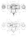
- valve fitting 6 located in the lower part of the radiator 1 is provided with a stop valve 8; 8' shown in Figures 2 to 7 for adjusting the amount of heat transfer liquid being discharged from the rear radiator 3.
- FIGS 2 to 4 show a preferred embodiment of the stop valve 8.
- This stop valve 8 comprises an insert 9 which is inserted into the valve fitting 6 and which, on the side of the front radiator plate 2, is provided with flow ports 12 which open into an interior 11 of the valve fitting 6 connected with an outlet 10 of the valve fitting 6, and which, on the side of the rear radiator plate 3, is provided with a flow channel 13 which also leads to the interior 11 of the valve fitting 6 connected with the outlet 10 of the valve fitting 6.
- the insert 9 is preferably a separate brass case which is mountable in place by means of threads provided on an outer surface of the insert 9 and an inner surface of the valve fitting 6.
- the closure member 14 is supported and pivotably mounted on a sleeve 17 formed in a central part of the valve fitting 6.
- the turning movement of the closure member 14 between a closed position and a completely opened position of the flow channel 13 is about 30°.
- the closure member is shown in an opened position.
- this closure member 14 is electrically driven.
- An electric drive may be arranged in a shaft 18 of the closure member 14 protruding from the sleeve 17.
- FIGS 5 to 7 show another preferred embodiment of the stop valve 8'.
- This stop valve 8' comprises an insert 9' which is inserted into the valve fitting 6 and which is almost identical with the insert 9 and which, on the side of the front radiator plate 2, is provided with flow ports 12' which open into the interior 11 of the valve fitting 6 connected with the outlet 10 of the valve fitting 6, and which, on the side of the rear radiator plate 3, is provided with a flow channel 13' which also leads to the interior 11 of the valve fitting 6 connected with the outlet 10 of the valve fitting 6.
- a base frame 6a of the valve fitting 6 is similar to that in the solution according to Figures 2 to 4 , the sleeve 17 of the valve fitting 6 being provided with a closure member 14' which is supported on the sleeve and which is movable perpendicularly to an axial direction of the valve fitting 6 in order to close and open the flow channel 13' of the insert 9' leading to the interior 11 of the valve fitting 6.
- the closure member 14' is provided with a valve disc 14a' which cooperates with an outlet 13a' of the flow channel 13'.
- the inserts 9 and 9' differ from one another mostly only as far as the surfaces coming into contact with the closure members 14 and 14' are concerned, which, when using different closure members, is an advantage in terms of manufacturing techniques.
- the closure member 14' is an electromagnetic valve.
- the electromagnetic valve is probably in practice a more advantageous solution than a turning closure member.
- the valve fitting 4 through which heat transfer liquid is delivered to the radiator 1, is provided with a radiator valve with a thermostat (neither being shown).
- the radiator valve thermostat arrangement depends on the manner of implementation of the valve fitting 4.
- the valve fitting 4 may, as distinct from Figure 1 , be e.g. provided in connection with an arrangement called an integrated valve structure, in which case the heat transfer liquid is delivered from the lower part of the radiator 1 along a pipe inside the radiator 1 upwards to be subsequently distributed from the upper part of the radiator into the radiator plates 1.
- these arrangements are irrelevant to the invention per se.
- the stop valve 8; 8' provided in the valve fitting 6 located in the lower part of the radiator 1 is controlled according to a particular temperature difference between a set temperature of the thermostat and the temperature of the space to be heated.
- This temperature difference may be about 1°C, for instance.
- the stop valve 8; 8' is opened when the temperature of the space to be heated is lower than the set value of the thermostat by a selected temperature difference.
- the stop valve 8; 8' is closed, and the heat transfer liquid then again circulates only through the front radiator plate 2.
- the control of the stop valve 8; 8' may be implemented preferably electrically by means of electronic communication between the thermostat of the radiator valve and the closure members 14; 14'.
Landscapes
- Engineering & Computer Science (AREA)
- General Engineering & Computer Science (AREA)
- Mechanical Engineering (AREA)
- Physics & Mathematics (AREA)
- Thermal Sciences (AREA)
- Chemical & Material Sciences (AREA)
- Combustion & Propulsion (AREA)
- Electromagnetism (AREA)
- Steam Or Hot-Water Central Heating Systems (AREA)
- Domestic Hot-Water Supply Systems And Details Of Heating Systems (AREA)
- Heat-Exchange Devices With Radiators And Conduit Assemblies (AREA)
Applications Claiming Priority (1)
| Application Number | Priority Date | Filing Date | Title |
|---|---|---|---|
| FI20135221A FI124384B (fi) | 2013-03-08 | 2013-03-08 | Lämpöpatteri ja menetelmä sen ohjaamiseksi |
Publications (2)
| Publication Number | Publication Date |
|---|---|
| EP2775222A2 true EP2775222A2 (fr) | 2014-09-10 |
| EP2775222A3 EP2775222A3 (fr) | 2017-04-26 |
Family
ID=50238203
Family Applications (1)
| Application Number | Title | Priority Date | Filing Date |
|---|---|---|---|
| EP14157994.6A Withdrawn EP2775222A3 (fr) | 2013-03-08 | 2014-03-06 | Radiateur, et procédé pour le contrôler |
Country Status (2)
| Country | Link |
|---|---|
| EP (1) | EP2775222A3 (fr) |
| FI (1) | FI124384B (fr) |
Cited By (3)
| Publication number | Priority date | Publication date | Assignee | Title |
|---|---|---|---|---|
| EP3184915A1 (fr) * | 2015-12-23 | 2017-06-28 | Rettig Austria GmbH | Dispositif comprenant un corps de soupape |
| DE102017001992A1 (de) | 2016-03-02 | 2017-09-07 | Rettig Icc B.V. | Heizkörper und zugehöriges Heizkörperventil |
| CN116147048A (zh) * | 2022-12-02 | 2023-05-23 | 珠海格力电器股份有限公司 | 一种电热油汀 |
Family Cites Families (4)
| Publication number | Priority date | Publication date | Assignee | Title |
|---|---|---|---|---|
| DE19709534A1 (de) * | 1997-03-10 | 1998-09-24 | Oventrop Sohn Kg F W | Von Fluid als Wärmeträger durchströmbarer Heizkörper |
| DE10019980A1 (de) * | 2000-01-08 | 2001-07-12 | Andreas Biedermann | Heizenergiesparendes Thermostatventil zur Raumtemperaturregelung |
| DE102007036141A1 (de) * | 2007-07-31 | 2009-02-05 | Kermi Gmbh | Heizkörper |
| CZ24685U1 (cs) * | 2012-10-22 | 2012-12-10 | Korado A.S. | Víceradé otopné teleso s rízeným prutokem topného média |
-
2013
- 2013-03-08 FI FI20135221A patent/FI124384B/fi not_active IP Right Cessation
-
2014
- 2014-03-06 EP EP14157994.6A patent/EP2775222A3/fr not_active Withdrawn
Non-Patent Citations (1)
| Title |
|---|
| None |
Cited By (3)
| Publication number | Priority date | Publication date | Assignee | Title |
|---|---|---|---|---|
| EP3184915A1 (fr) * | 2015-12-23 | 2017-06-28 | Rettig Austria GmbH | Dispositif comprenant un corps de soupape |
| DE102017001992A1 (de) | 2016-03-02 | 2017-09-07 | Rettig Icc B.V. | Heizkörper und zugehöriges Heizkörperventil |
| CN116147048A (zh) * | 2022-12-02 | 2023-05-23 | 珠海格力电器股份有限公司 | 一种电热油汀 |
Also Published As
| Publication number | Publication date |
|---|---|
| FI20135221A7 (fi) | 2014-08-15 |
| FI124384B (fi) | 2014-08-15 |
| EP2775222A3 (fr) | 2017-04-26 |
Similar Documents
| Publication | Publication Date | Title |
|---|---|---|
| KR102023619B1 (ko) | 냉수탱크 및 이를 구비하는 수처리 기기 | |
| EP2397777B1 (fr) | Unité de boîtier pour une installation de chauffage | |
| US9027844B2 (en) | Water delivery system and valve for a sink | |
| US11243017B2 (en) | Drained plumbing system for an ice maker | |
| FI124384B (fi) | Lämpöpatteri ja menetelmä sen ohjaamiseksi | |
| UA15108U (en) | Panel heating unit for combined heating | |
| KR102462954B1 (ko) | 탱크 안에 포함된 유체의 열교환 및 열적 성층 시스템 및 상기 시스템을 포함하는 온수 탱크 | |
| CN105486004A (zh) | 风道结构及冰箱 | |
| CN209655613U (zh) | 一种双温冷水机 | |
| US10772462B2 (en) | Heating device | |
| EP2221545A1 (fr) | Four de cuisson doté d'un accumulateur thermique latent | |
| CN111271492A (zh) | 一种小型热水器 | |
| EP2113059B1 (fr) | Appareil frigorifique comportant un réservoir d'eau | |
| KR101598213B1 (ko) | 물의 낭비를 최소화하기 위한 샤워기 조립체 | |
| KR20180104276A (ko) | 팬코일 유니트 | |
| EP2909538B1 (fr) | Radiateur multi-rangée à écoulement régulé du fluide chauffant | |
| ITMI20140288U1 (it) | Satellite per riscaldamento centralizzato o per teleriscaldamento con predisposizione a piu' funzioni | |
| CN206861963U (zh) | 冰箱 | |
| KR101781165B1 (ko) | 온수유량조절 난방시스템 및 그 제어방법 | |
| KR101671670B1 (ko) | 드레인장치 및 이를 구비한 열교환기 | |
| FI126971B (fi) | Lämpöpatteri ja patteriventtiilisisäke | |
| EP2917646B1 (fr) | Radiateur de chauffage d`un système de chauffage, le radiateur comprenant un élément de liaison assurant la liaison de deux plaques de radiateur | |
| US12514396B2 (en) | Drain tray for solenoid valves of machines for coffee dispensing and machine for coffee dispensing provided with said drain tray | |
| CN204969118U (zh) | 一种恒温的猪精冰箱 | |
| CN102349794A (zh) | 一种简单的降温装置 |
Legal Events
| Date | Code | Title | Description |
|---|---|---|---|
| PUAI | Public reference made under article 153(3) epc to a published international application that has entered the european phase |
Free format text: ORIGINAL CODE: 0009012 |
|
| 17P | Request for examination filed |
Effective date: 20140306 |
|
| AK | Designated contracting states |
Kind code of ref document: A2 Designated state(s): AL AT BE BG CH CY CZ DE DK EE ES FI FR GB GR HR HU IE IS IT LI LT LU LV MC MK MT NL NO PL PT RO RS SE SI SK SM TR |
|
| AX | Request for extension of the european patent |
Extension state: BA ME |
|
| PUAL | Search report despatched |
Free format text: ORIGINAL CODE: 0009013 |
|
| AK | Designated contracting states |
Kind code of ref document: A3 Designated state(s): AL AT BE BG CH CY CZ DE DK EE ES FI FR GB GR HR HU IE IS IT LI LT LU LV MC MK MT NL NO PL PT RO RS SE SI SK SM TR |
|
| AX | Request for extension of the european patent |
Extension state: BA ME |
|
| RIC1 | Information provided on ipc code assigned before grant |
Ipc: F16K 27/02 20060101ALI20170323BHEP Ipc: F24D 19/10 20060101ALI20170323BHEP Ipc: F24D 19/00 20060101AFI20170323BHEP Ipc: F16K 5/04 20060101ALI20170323BHEP Ipc: F16K 27/06 20060101ALI20170323BHEP Ipc: F16K 31/06 20060101ALI20170323BHEP |
|
| R17P | Request for examination filed (corrected) |
Effective date: 20171004 |
|
| RBV | Designated contracting states (corrected) |
Designated state(s): AL AT BE BG CH CY CZ DE DK EE ES FI FR GB GR HR HU IE IS IT LI LT LU LV MC MK MT NL NO PL PT RO RS SE SI SK SM TR |
|
| 17Q | First examination report despatched |
Effective date: 20180209 |
|
| STAA | Information on the status of an ep patent application or granted ep patent |
Free format text: STATUS: THE APPLICATION IS DEEMED TO BE WITHDRAWN |
|
| 18D | Application deemed to be withdrawn |
Effective date: 20180620 |