EP2775247B1 - Échangeur de chaleur à double motif d'alvéoles - Google Patents
Échangeur de chaleur à double motif d'alvéoles Download PDFInfo
- Publication number
- EP2775247B1 EP2775247B1 EP14153906.4A EP14153906A EP2775247B1 EP 2775247 B1 EP2775247 B1 EP 2775247B1 EP 14153906 A EP14153906 A EP 14153906A EP 2775247 B1 EP2775247 B1 EP 2775247B1
- Authority
- EP
- European Patent Office
- Prior art keywords
- heat exchanger
- dimples
- wall sections
- rows
- tops
- Prior art date
- Legal status (The legal status is an assumption and is not a legal conclusion. Google has not performed a legal analysis and makes no representation as to the accuracy of the status listed.)
- Active
Links
Images


Classifications
-
- F—MECHANICAL ENGINEERING; LIGHTING; HEATING; WEAPONS; BLASTING
- F28—HEAT EXCHANGE IN GENERAL
- F28F—DETAILS OF HEAT-EXCHANGE AND HEAT-TRANSFER APPARATUS, OF GENERAL APPLICATION
- F28F3/00—Plate-like or laminated elements; Assemblies of plate-like or laminated elements
- F28F3/02—Elements or assemblies thereof with means for increasing heat-transfer area, e.g. with fins, with recesses, with corrugations
- F28F3/04—Elements or assemblies thereof with means for increasing heat-transfer area, e.g. with fins, with recesses, with corrugations the means being integral with the element
- F28F3/042—Elements or assemblies thereof with means for increasing heat-transfer area, e.g. with fins, with recesses, with corrugations the means being integral with the element in the form of local deformations of the element
- F28F3/044—Elements or assemblies thereof with means for increasing heat-transfer area, e.g. with fins, with recesses, with corrugations the means being integral with the element in the form of local deformations of the element the deformations being pontual, e.g. dimples
-
- F—MECHANICAL ENGINEERING; LIGHTING; HEATING; WEAPONS; BLASTING
- F28—HEAT EXCHANGE IN GENERAL
- F28F—DETAILS OF HEAT-EXCHANGE AND HEAT-TRANSFER APPARATUS, OF GENERAL APPLICATION
- F28F3/00—Plate-like or laminated elements; Assemblies of plate-like or laminated elements
- F28F3/08—Elements constructed for building-up into stacks, e.g. capable of being taken apart for cleaning
- F28F3/083—Elements constructed for building-up into stacks, e.g. capable of being taken apart for cleaning capable of being taken apart
Definitions
- the invention relates to a heat exchanger comprising a plurality of heat exchanger plates, wherein each of the heat exchanger plates comprises a plurality of dimples, and wherein the dimples comprise tops and bottoms, and wherein the tops of at least one heat exchanger plate are connected to bottoms of another neighboring heat exchanger plate, and where the tops and bottoms are essentially flat such that a flat plane of a top meets a flat plane of a bottom when heat exchanger plates are connected, where at least part of the dimples comprising tops are arranged in first rows and at least part of the dimples comprising bottoms are arranged in second rows and where said at least part of the dimples are connected to at least one adjacent dimple by a wall section where at least some of the wall sections have the same height as the dimples forming closed dimple pairs and the wall sections of neighboring plates are in contact with each other completely blocking the fluid path where the closed dimple pairs and meet, characterized in that the wall section has a minimum width which is smaller than the maximum
- Plate heat exchangers are well known devices for the transport for heat between two different media, in particular fluids.
- Such plate heat exchangers usually comprise a plurality of heat exchanger plates, wherein each heat exchanger plate comprises a pattern of indentations as well as inlets and outlets for the two media.
- Each pair of neighboring plates is joined in such a way that channels for the transport of the separate media are created.
- the two media will then be allowed to circulate between alternating pairs of plates to allow a transfer of heat through the heat exchanger plates.
- the pattern of indentations of one plate will be in contact with the indentation patterns of the two neighboring plates. This way the plates are kept slightly spaced and the shape of the fluid path can be adjusted to improve the efficiency of the heat exchange.
- herringbone pattern of indentations comprising ridges and valleys that force the flow of the media to accelerate and decelerate repeatedly within the plane of the heat exchanger plate. This usually leads to a large variation of the speed, or flow rates, of the fluids which reduces the effectiveness of the heat transfer.
- a pattern of indentations that allows for a more homogeneous speed of the fluids would be beneficial.
- WO 88/08508 discloses a heat exchanger according to the preamble of claim 1.
- Each of US 2011/0120934 A1 and WO 2009/112031 A2 describes a heat exchanger comprising a plurality of dimpled heat exchanger plates, wherein at least part of the dimples are connected by a wall portion to one adjacent dimple.
- Such a construction has the disadvantage that the fluid flow is harder to direct and distribute across the whole plane of the heat exchanger plate. This is one reason why such heat exchangers and those having e.g. herringbone patterns, has relative slim and long designs, this reducing the width to which the fluids is to flow.
- This including the height and slope of the sides of the corrugations in herringbone patterns are the parameters that may be changed to obtain a given desired flow / pressure characteristic of the heat exchanger. Increasing the width of the channels by increasing the top surface area of the patterns would reduce the total heat exchange surface and this is not a desired option. Changing one parameter to obtain a desired pressure / flow / speed characteristic thus compromises another.
- the task of the invention is to provide a heat exchanger with a more advantageous pattern of indentations that allows for a higher stability and a reduced thickness of the heat exchanger plates.
- the present invention solves the above problem in that at least parts of the dimples are connected to at least one adjacent dimple by a wall section.
- the wall sections will at the one hand provide additional obstacles to the fluid flow, allowing to more effectively direct the fluid flow across the plane of the heat exchanger plates.
- the invention may be used for brazed heat exchangers as well as for gasketed heat exchangers or any other type of heat exchanger using heat exchanger plates.
- the dimples comprising tops will form pairs and the dimples comprising bottoms will form pairs, each of which are connected by one wall section.
- the wall sections have the same height as the dimples. Consequently the tops and/or the bottoms as well as the connecting wall section can form a single contact surface.
- height is used for both the height of the dimples comprising tops as well as for the depth of the dimples comprising bottoms, i.e. how far the dimple or wall section protrudes in a direction perpendicular to the plane of the heat exchanger plate.
- Such wall sections that have the same height as the dimples will thus completely block the fluid flow between the dimples they connect.
- the dimples and/or the wall sections comprise concave surface sections and/or convex surface sections.
- Such concave and/or convex surface sections will allow to more effectively direct the fluid flow along or around the wall sections. This may also prevent the occurrence of a laminar fluid flow if several subsequent wall sections should be arranged between several dimples along the same direction.
- the shape of the wall sections can also be adjusted to the shape of the dimples they connect. For example if the dimples have a substantially circular circumference comprising convex surface sections, then the wall sections could comprise mostly concave surface sections. Consequently the fluid would be forced to smoothly change the direction several times while flowing around the dimples connected by the wall sections.
- the wall sections connect three or more dimples. This could for example be the case if several wall sections connect dimples comprising tops or if several wall sections connect dimples comprising bottoms.
- Another example may be a plus-shaped group of five or more dimples connected by four or more wall sections.
- Such larger groups of dimples connected by wall sections may be beneficial to improve the stability of the heat exchanger plates locally or to produce larger obstacles for the fluid flow.
- the dimples and/or the wall sections are elastically deformable(or in alternative wording elastically compressible), in the context meaning that they may change shape slightly due to a bending of the wall material, but that this it is reversible.
- the dimples and/or the wall sections can deform elastically. Consequently plastic deformations that may lead to permanent damage to the heat exchanger will be avoided. Such strong forces for example occur in case of gasketed heat exchangers where relative pressures of the fluids changes.
- the wall sections have a minimum width that is smaller than a maximum width of the dimples.
- the wall sections will be relatively thin and not increase the contact surface of the two neighboring heat exchanger plates by a lot.
- two neighboring dimples that are connected to one another by a wall section could have a substantially 8-shaped circumference, forming a dimple pair. This would also significantly increase the total heat exchanging area.
- At least part of the dimples comprising tops are arranged in first rows and at least part of the dimples comprising bottoms are arranged in second rows.
- the fluid flow may be made to reach all parts of the heat exchanger plates resulting in a higher efficiency of the heat exchanger.
- the fluid flow will be reduced or completely blocked depending on the height of the wall sections.
- the second rows comprising bottoms the fluid flow may be enhanced.
- each first row as well as in each second row are connected by wall sections. Consequently relatively large obstacles for the fluid flow as well as relatively long fluid pathways can be created within the plane of the heat exchanger plate. If the wall sections in this case comprise convex and/or concave surface sections the fluid flow along the wall sections will be improved, because the occurrence of a laminar fluid flow along such extended fluid barriers can be avoided.
- each first row and in each second row wall sections with the same height as the dimples are arranged alternately with wall sections with a lower height as the dimples.
- first and second rows will not form impenetrable barriers to the fluid flow, but rather shape the main directions of the fluid flow while still allowing some of the fluid to pass at wall sections with a lower height.
- first and second rows are arranged parallel to an edge of the heat exchanger plate.
- first and second rows are arranged at an angle to an edge of the heat exchanger plate.
- some of the first and second rows may be arranged at an angle of 20° to less than 45° to an edge of the heat exchanger plate.
- first and second rows change direction within the plane of the heat exchanger plate. Consequently the first and second rows may for example form wedges or zig-zag patterns within the plane of the heat exchanger plate to optimize the fluid flow.
- At least part of the dimples comprising tops are arranged alternately with dimples comprising bottoms along a direction parallel to an edge of the heat exchanger plate. Consequently the fluids will be forced to change their direction repeatedly to flow around the dimples for example in a slalom-like path.
- At least part of the dimples comprising tops are arranged alternately with dimples comprising bottoms along a direction inclined to an edge of the heat exchanger plate. This way one may create relatively direct fluid pathways in a direction inclined to an edge of the heat exchanger plate. Such a pattern may for example be beneficial close to the inlet as well as close to the outlet of the heat exchanger plate. Consequently the fluid flow can be either spread out from an inlet or be brought together to flow into the outlet.
- a cut view of a heat exchanger 1 comprising a plurality of heat exchanger plates 2 is shown.
- the heat exchanger plates 2 are stacked on top of each other creating a plurality of fluid paths between them.
- the heat exchanger plates 2 are arranged between top and bottom plates 3. Consequently, the heat exchanger plates 2 may be held under a pretension by an external pressure.
- Forces 4 can for example be introduced by connecting the top and bottom plates 3 by a way of introducing bolts through bores in the top and bottom plate 3 as well as the heat exchanger plates 2.
- Fig. 2a therein shows a contact area 5 of two heat exchanger plates 2.
- the contact area 5 is in this case formed by a valley of the top heat exchanger plate 2 meeting a ridge of a bottom heat exchanger plate 2.
- the contact area 5 of the two neighboring heat exchanger plates 2 is chosen to be very small.
- Fig. 4 now shows a cut view of a heat exchanger plate 2 according to the invention, in particular a pair of dimples 6 comprising tops 7.
- the following description of the embodiment of a pair of dimples 6 comprising tops 7 may be realized correspondingly for dimples 6 comprising bottoms 9.
- a pair of adjacent dimples 6 comprising tops 7 is connected to each other by a wall section 10.
- the wall section 10 has the same height as the dimples 6 that it connects. Consequently the pair of dimples 6 together with the wall section 10 may form a closed barrier to the fluid flow.
- the wall section 10 has a minimum width 11 that is smaller than the maximum width 12 of the dimples 6 it connects, thus increasing the heat transfer area. Consequently the wall section 10 will only slightly increase the contact area of the heat exchanger plates 2. Furthermore the wall section 10 in this case comprises concave surface sections 13. At the same time the dimples 6 comprise convex surface sections 14.
- the circumference of such a pair of dimples comprising a wall section may be of any shape, for example the wall section 10 may also comprise convex surface sections 14 or the dimples 6 may comprise concave surface sections 13.
- a pair of dimples 6 as disclosed in Fig. 4 thus forms a closed dimple pair 15 that may completely block the fluid flow between them.
- a different embodiment of a pair of dimples 6 is disclosed, which is not covered by the present invention.
- the wall section 10a between the two dimples 6 comprising tops 7 has a lower height as the dimples 6 and in particular the tops 7.
- the pair of dimples 6 does in this case form an open dimple pair 16.
- a top view of the open dimple pair 16 is shown.
- the wall section 10a is in this top view not shown. This does not mean that the wall section 10a is not present, but rather that an open fluid path is present between the two dimples 6.
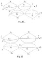
- Fig. 6a and 6b show on the left side a simplified top view of a heat exchanger plate 2. On the right side of Fig. 6a and 6b enlarged views of small sections of the heat exchanger plate 2 is disclosed.
- closed dimple pairs 15 comprising tops 7 are arranged in first rows 17.
- closed dimple pairs 15a comprising bottoms 9 are arranged in second rows 18.
- substantially direct fluid paths 19 will open up in diagonal directions along the dashed lines.
- the first rows 17 comprising tops 7 form barriers to the fluid flow.
- the closed dimple pairs 15 completely block the fluid flow, while the tops 7 of adjacent closed dimple pairs 15 may either not be connected by a wall section 10, 10a or they may form an open dimple pair 16. Either way at least some fluid flow between each pair of adjacent closed dimple pairs 15 is possible in each of the shown first rows 17.
- closed dimple pairs 15a comprising bottoms 9 are arranged.
- the fluid can flow more or less freely.
- the relative arrangement of the closed dimple pairs 15 comprising tops 7 relative to the closed dimple pairs 15a comprising bottoms 9 one may in this case choose whether the fluid will preferably flow to the left or to the right when coming from above.
- dimples 6 comprising tops 7 are arranged alternately with dimples 8 comprising bottoms 9 along a direction inclined to an edge 20 of the heat exchanger plate 2.
- Fig. 6b an alternative embodiment of a heat exchanger plate 2 according to the invention is disclosed.
- the relative arrangement of the dimples 6 comprising tops 7 to the dimples 8 comprising bottoms 9 is changed as compared to Fig. 6a .
- the dimples 6 comprising tops 7 are arranged alternately with dimples 8 comprising bottoms 9 along a direction parallel to an edge 20 of the heat exchanger plate 2.
- each first row 17 is followed by a second row 18, wherein the closed dimples 15, 15a are arranged synchronously in both rows. For the following two rows 17, 18 the closed dimple pairs 15, 15a will be displaced compared to the previous two rows 17, 18.
- the fluid path 21 will in this case be slalom-like in shape.
- the fluid path 21 may change the direction in each first row 17. This way it is ensured that the fluid has to change direction repeatedly ensuring that the fluid reaches all parts of the heat exchanger plate 2 evenly. At the same time the distance the fluids have to cover will be increased without forcing too abrupt direction changes onto the fluids.
- FIG. 7a, 7b and 7c three different ways of arranging the first rows 17 and second rows 18 within the plane of the heat exchanger plate 2 are disclosed.
- First rows 17 are shown as solid lines, while second rows 18 are shown as dashed lines.
- Fig. 7a, 7b and 7c it is not in detail shown where sections 10 with the same height as the dimples 7, 9 are arranged and where wall sections 10a with a lower height as the dimples 7, 9 appear.
- Fig. 7a the first rows 17 and second rows 18 are arranged parallel to an edge 22 of the heat exchanger plate 2. Consequently the arrangement is similar to the ones shown in Fig. 6a and 6b .
- Fig. 7b the first rows 17 and second rows 18 are arranged inclined to an edge 22 of the heat exchanger plate 2.
- Fig. 7c where the first rows 17 and second rows 18 change direction within the plane of the heat exchanger plate 2.
- the first rows 17 and second rows 18 form wedges 23 in the heat exchanger plate 2.
- the first rows 17 and second rows 18 may also change direction several times within the plane of the heat exchanger plate 2.
- first rows 17 and the second rows 18 may be used to achieve an optimal distribution of the fluid flow over the whole plane of the heat exchanger plate 2 to improve the efficiency of the heat exchanger 1.
- Fig. 8 a cross section of two neighboring heat exchanger plates 2a and 2b is shown. Therein the heat exchanger plate 2a is arranged below the heat exchanger plate 2b.
- Fig. 8 here shows how a first row 17 comprising tops 7 of the lower heat exchanger plate 2a is in contact with a second row 18 comprising bottoms 9 of the upper heat exchanger plate 2b.
- Dimples 6 comprising tops 7 are in contact with dimples 8 comprising bottoms 9.
- closed dimple pairs 15 comprising tops 7 are alternating with open dimple pairs 16 also comprising tops 7 in the lower heat exchanger plate 2a.
- Fig. 9a shows a horizontal cut view through a heat exchanger plate 2 according to the embodiment shown in Fig. 6a .
- the solid line here shows a first row 17 comprising tops 7 while the dashed lines show a second row 18 comprising bottoms 9 arranged adjacent to the first row 17.
- open dimple pairs 16 comprising tops 7 alternate with closed dimple pairs 15 comprising tops 7.
- open dimple pairs 16a comprising bottoms 9 alternate with closed dimple pairs 16 comprising bottoms 9.
- Fig. 9b a horizontal cut view through a heat exchanger plate 2 according to the embodiment shown in Fig. 6b is shown.
- the solid lines show a first row 17 while the dashed lines show a second row 18 arranged adjacent to the first row 17.
- dimples 6 comprising tops 7 are arranged alternately with dimples 8 comprising bottoms along a direction parallel to the edge 20 of the heat exchanger plate 2.
- wall sections 10a with a lower height as the dimples are arranged alternately with wall sections 10 with the same height as the dimples both in the first row 17 as well as in the second row 18.
- Fig. 9a and 9b also show an alternative shape of the dimples 6, 8.
- the dimples 6, 8 comprise flanks 24 that are substantially ellipse-shaped between adjacent tops and between adjacent bottoms. This way one may for example ensure that the dimples 6, 8 are elastically deformable.
- the flanks 24 may also be substantially straight as shown in Fig. 8 . If the dimples 6, 8 are elastically deformable the heat exchanger plates 2 will be more resistant to the large forces acting upon them caused by the internal fluid pressures as well as for gasketed heat exchangers the pre-tension forces.
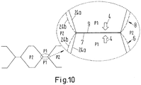
- Fig. 10 an elastic deformation of a pair of dimples 6, 8 in contact with each other at a top 7 and a bottom 9 is shown, this being due to the pressure P1 of the fluid at the one side of the flank 24 being larger than the pressure P2 of the fluid at the other side of the flank 24.
- flanks 24 will deform elastically from non-deformed flanks 24a into deformed flanks 24b.
- deformed shapes are shown by dashed lines, while non-deformed shapes are shown as solid lines.
Landscapes
- Engineering & Computer Science (AREA)
- Physics & Mathematics (AREA)
- Thermal Sciences (AREA)
- Mechanical Engineering (AREA)
- General Engineering & Computer Science (AREA)
- Heat-Exchange Devices With Radiators And Conduit Assemblies (AREA)
Claims (14)
- Échangeur de chaleur comprenant une pluralité de plaques d'échangeur de chaleur (2), chacune des plaques d'échangeur de chaleur (2) comprenant une pluralité d'alvéoles (6, 8), et les alvéoles (6, 8) comprenant des sommets (7) et des fonds (9), et les sommets (7) d'au moins une plaque d'échangeur de chaleur (2) étant reliés à des fonds (9) d'une autre plaque d'échangeur de chaleur voisine (2), et les sommets (7) et les fonds (9) étant plats de telle sorte qu'un plan plat d'une partie supérieure (7) rencontre un plan plat d'un fond (9) lorsque des plaques d'échangeur de chaleur (2) sont reliées, au moins une partie des alvéoles (6) comprenant des sommets (7) étant agencées en premières rangées (17) et au moins une partie des alvéoles (8) comprenant des fonds (9) étant agencées dans des secondes rangées (18) et ladite au moins une partie des alvéoles (6, 8) étant reliées à au moins une alvéole adjacente (6, 8) par une partie de paroi (10),
au moins certaines des sections de paroi (10) ayant la même hauteur que les alvéoles (6, 8), formant des paires d'alvéoles fermées (15, 15a) et des sections de paroi (10, 10a) de plaques voisines étant en contact l'une avec l'autre, bloquant complètement le trajet de fluide où les paires d'alvéoles fermées (15) et (15a) se rencontrent,
caractérisé en ce que :
la section de paroi (10) a une largeur minimale (11) qui est inférieure à la largeur maximale (12) des alvéoles (6) qu'elle relie. - Échangeur de chaleur selon la revendication 1, caractérisé en ce qu'au moins certaines des sections de paroi (10a) ont une hauteur inférieure à celle des alvéoles (6, 8).
- Échangeur de chaleur selon l'une quelconque des revendications 1 à 2, caractérisé en ce qu'au moins certaines des alvéoles (6, 8) et/ou des sections de paroi (10, 10a) comprennent des sections de surface concaves (13) et/ou des sections de surface convexes (14).
- Échangeur de chaleur selon l'une quelconque des revendications 1 à 3, caractérisé en ce qu'au moins certaines des sections de paroi (10, 10a) relient trois alvéoles ou plus (6, 8).
- Échangeur de chaleur selon l'une quelconque des revendications 1 à 4, caractérisé en ce que les alvéoles (6, 8) et/ou les sections de paroi (10, 10a) sont élastiquement déformables.
- Échangeur de chaleur selon l'une quelconque des revendications 2 à 5, caractérisé en ce qu'au moins certaines des sections de paroi (10a) ayant une hauteur inférieure à celle des alvéoles (6, 8) ont une largeur minimale (11) qui est inférieure à une largeur maximale (12) des alvéoles (6, 8).
- Échangeur de chaleur selon la revendication 1, caractérisé en ce que toutes les alvéoles (6) dans chaque première rangée (17) ainsi que toutes les alvéoles (8) dans chaque seconde rangée (18) sont reliées par des sections de paroi (10, 10a).
- Échangeur de chaleur selon la revendication 1 ou 7, caractérisé en ce que dans chaque première rangée (17) et dans chaque seconde rangée (18) des sections de paroi (10) ayant la même hauteur que les alvéoles (6, 8) sont agencées en alternance avec des sections de paroi (10a) ayant une hauteur inférieure à celles des alvéoles (6, 8).
- Échangeur de chaleur selon l'une quelconque des revendications 6 à 8, caractérisé en ce qu'au moins une partie des première et seconde rangées (17, 18) sont agencées parallèlement à un bord (20, 22) de la plaque d'échangeur de chaleur (2).
- Échangeur de chaleur selon l'une quelconque des revendications 6 à 9, caractérisé en ce qu'au moins une partie des première et seconde rangées (17, 18) sont agencées selon un angle par rapport à un bord (20, 22) de la plaque d'échangeur de chaleur (2).
- Échangeur de chaleur selon l'une quelconque des revendications 6 à 10, caractérisé en ce qu'au moins une partie des première et seconde rangées (17, 18) changent la direction dans le plan de la plaque d'échangeur de chaleur (2).
- Échangeur de chaleur selon l'une quelconque des revendications 1 à 11, caractérisé en ce qu'au moins une partie des alvéoles (6) comprenant des sommets (7) sont agencées en alternance avec des alvéoles (8) comprenant des fonds (9) le long d'une direction parallèle à un bord (20, 22) de la plaque d'échangeur de chaleur (2).
- Échangeur de chaleur selon l'une quelconque des revendications 1 à 12, caractérisé en ce qu'au moins une partie des alvéoles (6) comprenant des sommets (7) sont agencées en alternance avec des alvéoles (8) comprenant des fonds (9) le long d'une direction inclinée par rapport à un bord (20, 22) de la plaque d'échangeur de chaleur (2).
- Échangeur de chaleur selon la revendication 1, caractérisé en ce que les alvéoles (6, 8) sont de formes similaires.
Priority Applications (1)
| Application Number | Priority Date | Filing Date | Title |
|---|---|---|---|
| PL14153906T PL2775247T3 (pl) | 2013-03-08 | 2014-02-05 | Wymiennik ciepła o wzorze podwójnych wgłębień |
Applications Claiming Priority (1)
| Application Number | Priority Date | Filing Date | Title |
|---|---|---|---|
| DK201300126A DK177839B1 (en) | 2013-03-08 | 2013-03-08 | Heat exchanger with dimples connected by wall sections |
Publications (3)
| Publication Number | Publication Date |
|---|---|
| EP2775247A2 EP2775247A2 (fr) | 2014-09-10 |
| EP2775247A3 EP2775247A3 (fr) | 2015-09-02 |
| EP2775247B1 true EP2775247B1 (fr) | 2018-11-28 |
Family
ID=50031240
Family Applications (1)
| Application Number | Title | Priority Date | Filing Date |
|---|---|---|---|
| EP14153906.4A Active EP2775247B1 (fr) | 2013-03-08 | 2014-02-05 | Échangeur de chaleur à double motif d'alvéoles |
Country Status (6)
| Country | Link |
|---|---|
| US (1) | US10113814B2 (fr) |
| EP (1) | EP2775247B1 (fr) |
| CN (1) | CN104034190B (fr) |
| DK (2) | DK177839B1 (fr) |
| PL (1) | PL2775247T3 (fr) |
| RU (1) | RU2561356C1 (fr) |
Families Citing this family (10)
| Publication number | Priority date | Publication date | Assignee | Title |
|---|---|---|---|---|
| DE112014000721T5 (de) * | 2013-02-08 | 2015-10-29 | Dana Canada Corporation | Wärmetauscher mit ringförmigem Einlass/Auslass-Anschlussstück |
| DK177838B1 (en) | 2013-03-08 | 2014-09-08 | Danfoss As | A gasketed heat exchanger with elastically deformable dimples |
| EP3015809B1 (fr) * | 2014-10-31 | 2019-07-31 | Danfoss A/S | Échangeur thermique de plaque |
| CN107036479B (zh) * | 2016-02-04 | 2020-05-12 | 丹佛斯微通道换热器(嘉兴)有限公司 | 换热板以及使用其的板式换热器 |
| GB2552956A (en) * | 2016-08-15 | 2018-02-21 | Hs Marston Aerospace Ltd | Heat exchanger device |
| JP6322750B2 (ja) * | 2017-04-24 | 2018-05-09 | 株式会社日阪製作所 | プレート式熱交換器 |
| EP3650795B1 (fr) * | 2018-11-07 | 2021-03-17 | Alfa Laval Corporate AB | Plaque de transfert de chaleur |
| CN111366013A (zh) * | 2018-12-26 | 2020-07-03 | 浙江盾安热工科技有限公司 | 扁管及换热器 |
| KR20240089107A (ko) * | 2021-10-01 | 2024-06-20 | 에밥코 인코포레이티드 | 직접 열교환 충진재 |
| EP4506649B1 (fr) | 2023-08-11 | 2025-10-01 | Modine Manufacturing Company | Configuration d'alvéoles d'échangeur de chaleur |
Citations (1)
| Publication number | Priority date | Publication date | Assignee | Title |
|---|---|---|---|---|
| EP1122505A1 (fr) * | 1998-10-15 | 2001-08-08 | Ebara Corporation | Echangeur thermique a plaques |
Family Cites Families (41)
| Publication number | Priority date | Publication date | Assignee | Title |
|---|---|---|---|---|
| US2281754A (en) | 1937-01-27 | 1942-05-05 | Cherry Burreil Corp | Heat exchanger |
| US2441476A (en) | 1944-08-10 | 1948-05-11 | Glenn L Martin Co | Reinforced structural sheet |
| US2481046A (en) | 1947-11-13 | 1949-09-06 | Western Engineering Associates | Panel structure |
| US2577321A (en) | 1949-10-29 | 1951-12-04 | Joseph B Filger | Nose drop dispenser |
| US2627283A (en) * | 1950-11-27 | 1953-02-03 | Fedders Quigan Corp | Heat exchange conduit for oil coolers |
| GB901914A (en) | 1959-12-02 | 1962-07-25 | Nat Res Dev | Improvements in or relating to heat exchangers |
| US3532161A (en) | 1968-06-27 | 1970-10-06 | Aqua Chem Inc | Plate type heat exchanger |
| US3597891A (en) | 1969-10-02 | 1971-08-10 | Mc Donnell Douglas Corp | Interior absorptive panel |
| US3664928A (en) * | 1969-12-15 | 1972-05-23 | Aerojet General Co | Dimpled heat transfer walls for distillation apparatus |
| SE353954B (fr) * | 1971-02-19 | 1973-02-19 | Alfa Laval Ab | |
| US3742663A (en) | 1971-08-02 | 1973-07-03 | Mc Donnell Douglas Corp | Panel blocking |
| US3956543A (en) | 1972-10-02 | 1976-05-11 | Rockwell International Corporation | Shear flexibility for structures |
| GB1468514A (en) | 1974-06-07 | 1977-03-30 | Apv Co Ltd | Plate heat exchangers |
| SE415928B (sv) | 1979-01-17 | 1980-11-10 | Alfa Laval Ab | Plattvermevexlare |
| US4291759A (en) * | 1979-08-28 | 1981-09-29 | Hisaka Works, Limited | Cross-current type plate heat exchanger |
| SU992995A1 (ru) * | 1981-04-17 | 1983-01-30 | Львовский Ордена Ленина Политехнический Институт Им.Ленинского Комсомола | Пластинчатый теплообменник |
| US4471759A (en) * | 1981-04-28 | 1984-09-18 | B. Shawn Buckley | Method of forming a solar collector or hot water storage tank and solar water heating apparatus using same |
| SU1257402A2 (ru) | 1984-09-07 | 1986-09-15 | Ярославский Моторный Завод "Автодизель" | Пластинчатый теплообменник |
| DE3622316C1 (de) | 1986-07-03 | 1988-01-28 | Schmidt W Gmbh Co Kg | Plattenwaermeaustauscher |
| SE458806B (sv) * | 1987-04-21 | 1989-05-08 | Alfa Laval Thermal Ab | Plattvaermevaexlare med olika stroemningsmotstaand foer medierna |
| US4919200A (en) * | 1989-05-01 | 1990-04-24 | Stanislas Glomski | Heat exchanger wall assembly |
| SE468685B (sv) | 1991-06-24 | 1993-03-01 | Alfa Laval Thermal Ab | Plattvaermevaexlare med plattor som har aasar och raennor daer aasar paa en platta anligger mot parallellt med desamma loepande aasar paa den andra plattan |
| JPH0942865A (ja) * | 1995-07-28 | 1997-02-14 | Honda Motor Co Ltd | 熱交換器 |
| US5643656A (en) | 1995-08-14 | 1997-07-01 | Lin; Tso Nan | Packing cushion board |
| SE9503241D0 (sv) | 1995-09-26 | 1995-09-26 | Tetra Laval Holdings & Finance | Plattvärmeväxlare |
| US5968321A (en) | 1996-02-13 | 1999-10-19 | Ridgewood Waterpure Corporation | Vapor compression distillation system and method |
| JP4072876B2 (ja) * | 1998-05-22 | 2008-04-09 | セキサーマル株式会社 | 積層型熱交換器 |
| US6221463B1 (en) | 1998-07-08 | 2001-04-24 | Eugene W. White | Three-dimensional film structures and methods |
| RU2164332C2 (ru) | 1999-03-02 | 2001-03-20 | Открытое акционерное общество Уральский торговый дом "Логика" | Пакет пластин для теплообменника |
| US6357516B1 (en) | 2000-02-02 | 2002-03-19 | York International Corporation | Plate heat exchanger assembly with enhanced heat transfer characteristics |
| SE518256C2 (sv) | 2001-01-04 | 2002-09-17 | Alfa Laval Ab | Värmeöverföringsplatta, plattpaket samt plattvärmeväxlare |
| US6595273B2 (en) * | 2001-08-08 | 2003-07-22 | Denso Corporation | Heat exchanger |
| SE528629C2 (sv) | 2004-09-08 | 2007-01-09 | Ep Technology Ab | Rillmönster för värmeväxlare |
| US20110180247A1 (en) | 2004-09-08 | 2011-07-28 | Ep Technology Ab | Heat exchanger |
| US20070006998A1 (en) | 2005-07-07 | 2007-01-11 | Viktor Brost | Heat exchanger with plate projections |
| EP1933105A1 (fr) | 2006-12-11 | 2008-06-18 | Invensys APV A/S | Plaque d'échangeur thermique |
| AU2009225118B2 (en) * | 2008-03-13 | 2012-02-02 | Danfoss A/S | A double plate heat exchanger |
| DK2257756T3 (en) | 2008-04-04 | 2015-01-05 | Alfa Laval Corp Ab | Plate heat exchange |
| US20110120934A1 (en) * | 2009-11-24 | 2011-05-26 | Air To Air Sweden Ab | Method of producing multiple channels for use in a device for exchange of solutes between fluid flows |
| RU2502932C2 (ru) * | 2010-11-19 | 2013-12-27 | Данфосс А/С | Теплообменник |
| DK177838B1 (en) | 2013-03-08 | 2014-09-08 | Danfoss As | A gasketed heat exchanger with elastically deformable dimples |
-
2013
- 2013-03-08 DK DK201300126A patent/DK177839B1/en active
-
2014
- 2014-02-05 EP EP14153906.4A patent/EP2775247B1/fr active Active
- 2014-02-05 DK DK14153906.4T patent/DK2775247T3/en active
- 2014-02-05 PL PL14153906T patent/PL2775247T3/pl unknown
- 2014-03-04 US US14/196,237 patent/US10113814B2/en active Active
- 2014-03-05 RU RU2014108232/06A patent/RU2561356C1/ru active
- 2014-03-10 CN CN201410085610.6A patent/CN104034190B/zh active Active
Patent Citations (1)
| Publication number | Priority date | Publication date | Assignee | Title |
|---|---|---|---|---|
| EP1122505A1 (fr) * | 1998-10-15 | 2001-08-08 | Ebara Corporation | Echangeur thermique a plaques |
Also Published As
| Publication number | Publication date |
|---|---|
| PL2775247T3 (pl) | 2019-05-31 |
| DK2775247T3 (en) | 2019-03-04 |
| EP2775247A2 (fr) | 2014-09-10 |
| CN104034190B (zh) | 2017-12-08 |
| US10113814B2 (en) | 2018-10-30 |
| CN104034190A (zh) | 2014-09-10 |
| EP2775247A3 (fr) | 2015-09-02 |
| DK177839B1 (en) | 2014-09-08 |
| US20140251587A1 (en) | 2014-09-11 |
| RU2561356C1 (ru) | 2015-08-27 |
Similar Documents
| Publication | Publication Date | Title |
|---|---|---|
| EP2775247B1 (fr) | Échangeur de chaleur à double motif d'alvéoles | |
| EP3436759B1 (fr) | Plaque de transfert de chaleur et échangeur de chaleur à plaques comprenant une pluralité de ces plaques de transfert de chaleur | |
| CN110537069B (zh) | 热传递板和包括多个此类热传递板的热交换器 | |
| EP2775246B1 (fr) | Échangeur de chaleur avec joint d'étanchéité, à motif d'alvéoles | |
| EP1723376B1 (fr) | Plaque d'echangeur thermique et bloc de plaques | |
| JP7214923B2 (ja) | 熱伝達プレート | |
| US20060185835A1 (en) | Heat exchange plate | |
| JP2006317029A (ja) | 熱交換ユニット | |
| US20070151717A1 (en) | Heat exchange plate | |
| JP7724219B2 (ja) | 停滞した媒体を回避するくぼみを備えた熱交換器 | |
| KR102637998B1 (ko) | 열전달 플레이트 | |
| KR20050073424A (ko) | 열교환용 플레이트 및 열교환 유닛 | |
| CN114877742B (zh) | 一种板式换热器的板片 | |
| KR102638063B1 (ko) | 열전달 플레이트 |
Legal Events
| Date | Code | Title | Description |
|---|---|---|---|
| PUAI | Public reference made under article 153(3) epc to a published international application that has entered the european phase |
Free format text: ORIGINAL CODE: 0009012 |
|
| 17P | Request for examination filed |
Effective date: 20140205 |
|
| AK | Designated contracting states |
Kind code of ref document: A2 Designated state(s): AL AT BE BG CH CY CZ DE DK EE ES FI FR GB GR HR HU IE IS IT LI LT LU LV MC MK MT NL NO PL PT RO RS SE SI SK SM TR |
|
| AX | Request for extension of the european patent |
Extension state: BA ME |
|
| PUAL | Search report despatched |
Free format text: ORIGINAL CODE: 0009013 |
|
| AK | Designated contracting states |
Kind code of ref document: A3 Designated state(s): AL AT BE BG CH CY CZ DE DK EE ES FI FR GB GR HR HU IE IS IT LI LT LU LV MC MK MT NL NO PL PT RO RS SE SI SK SM TR |
|
| AX | Request for extension of the european patent |
Extension state: BA ME |
|
| RIC1 | Information provided on ipc code assigned before grant |
Ipc: F28F 3/04 20060101AFI20150724BHEP Ipc: F28F 3/08 20060101ALI20150724BHEP |
|
| R17P | Request for examination filed (corrected) |
Effective date: 20160203 |
|
| RBV | Designated contracting states (corrected) |
Designated state(s): AL AT BE BG CH CY CZ DE DK EE ES FI FR GB GR HR HU IE IS IT LI LT LU LV MC MK MT NL NO PL PT RO RS SE SI SK SM TR |
|
| STAA | Information on the status of an ep patent application or granted ep patent |
Free format text: STATUS: EXAMINATION IS IN PROGRESS |
|
| 17Q | First examination report despatched |
Effective date: 20170403 |
|
| GRAP | Despatch of communication of intention to grant a patent |
Free format text: ORIGINAL CODE: EPIDOSNIGR1 |
|
| STAA | Information on the status of an ep patent application or granted ep patent |
Free format text: STATUS: GRANT OF PATENT IS INTENDED |
|
| INTG | Intention to grant announced |
Effective date: 20180912 |
|
| GRAS | Grant fee paid |
Free format text: ORIGINAL CODE: EPIDOSNIGR3 |
|
| GRAA | (expected) grant |
Free format text: ORIGINAL CODE: 0009210 |
|
| STAA | Information on the status of an ep patent application or granted ep patent |
Free format text: STATUS: THE PATENT HAS BEEN GRANTED |
|
| AK | Designated contracting states |
Kind code of ref document: B1 Designated state(s): AL AT BE BG CH CY CZ DE DK EE ES FI FR GB GR HR HU IE IS IT LI LT LU LV MC MK MT NL NO PL PT RO RS SE SI SK SM TR |
|
| REG | Reference to a national code |
Ref country code: CH Ref legal event code: EP |
|
| REG | Reference to a national code |
Ref country code: AT Ref legal event code: REF Ref document number: 1070720 Country of ref document: AT Kind code of ref document: T Effective date: 20181215 |
|
| REG | Reference to a national code |
Ref country code: DE Ref legal event code: R096 Ref document number: 602014036779 Country of ref document: DE |
|
| REG | Reference to a national code |
Ref country code: IE Ref legal event code: FG4D |
|
| REG | Reference to a national code |
Ref country code: DK Ref legal event code: T3 Effective date: 20190225 |
|
| REG | Reference to a national code |
Ref country code: NL Ref legal event code: FP |
|
| REG | Reference to a national code |
Ref country code: LT Ref legal event code: MG4D |
|
| REG | Reference to a national code |
Ref country code: AT Ref legal event code: MK05 Ref document number: 1070720 Country of ref document: AT Kind code of ref document: T Effective date: 20181128 |
|
| PG25 | Lapsed in a contracting state [announced via postgrant information from national office to epo] |
Ref country code: LV Free format text: LAPSE BECAUSE OF FAILURE TO SUBMIT A TRANSLATION OF THE DESCRIPTION OR TO PAY THE FEE WITHIN THE PRESCRIBED TIME-LIMIT Effective date: 20181128 Ref country code: ES Free format text: LAPSE BECAUSE OF FAILURE TO SUBMIT A TRANSLATION OF THE DESCRIPTION OR TO PAY THE FEE WITHIN THE PRESCRIBED TIME-LIMIT Effective date: 20181128 Ref country code: BG Free format text: LAPSE BECAUSE OF FAILURE TO SUBMIT A TRANSLATION OF THE DESCRIPTION OR TO PAY THE FEE WITHIN THE PRESCRIBED TIME-LIMIT Effective date: 20190228 Ref country code: LT Free format text: LAPSE BECAUSE OF FAILURE TO SUBMIT A TRANSLATION OF THE DESCRIPTION OR TO PAY THE FEE WITHIN THE PRESCRIBED TIME-LIMIT Effective date: 20181128 Ref country code: HR Free format text: LAPSE BECAUSE OF FAILURE TO SUBMIT A TRANSLATION OF THE DESCRIPTION OR TO PAY THE FEE WITHIN THE PRESCRIBED TIME-LIMIT Effective date: 20181128 Ref country code: IS Free format text: LAPSE BECAUSE OF FAILURE TO SUBMIT A TRANSLATION OF THE DESCRIPTION OR TO PAY THE FEE WITHIN THE PRESCRIBED TIME-LIMIT Effective date: 20190328 Ref country code: NO Free format text: LAPSE BECAUSE OF FAILURE TO SUBMIT A TRANSLATION OF THE DESCRIPTION OR TO PAY THE FEE WITHIN THE PRESCRIBED TIME-LIMIT Effective date: 20190228 Ref country code: AT Free format text: LAPSE BECAUSE OF FAILURE TO SUBMIT A TRANSLATION OF THE DESCRIPTION OR TO PAY THE FEE WITHIN THE PRESCRIBED TIME-LIMIT Effective date: 20181128 Ref country code: FI Free format text: LAPSE BECAUSE OF FAILURE TO SUBMIT A TRANSLATION OF THE DESCRIPTION OR TO PAY THE FEE WITHIN THE PRESCRIBED TIME-LIMIT Effective date: 20181128 |
|
| PG25 | Lapsed in a contracting state [announced via postgrant information from national office to epo] |
Ref country code: SE Free format text: LAPSE BECAUSE OF FAILURE TO SUBMIT A TRANSLATION OF THE DESCRIPTION OR TO PAY THE FEE WITHIN THE PRESCRIBED TIME-LIMIT Effective date: 20181128 Ref country code: AL Free format text: LAPSE BECAUSE OF FAILURE TO SUBMIT A TRANSLATION OF THE DESCRIPTION OR TO PAY THE FEE WITHIN THE PRESCRIBED TIME-LIMIT Effective date: 20181128 Ref country code: RS Free format text: LAPSE BECAUSE OF FAILURE TO SUBMIT A TRANSLATION OF THE DESCRIPTION OR TO PAY THE FEE WITHIN THE PRESCRIBED TIME-LIMIT Effective date: 20181128 Ref country code: GR Free format text: LAPSE BECAUSE OF FAILURE TO SUBMIT A TRANSLATION OF THE DESCRIPTION OR TO PAY THE FEE WITHIN THE PRESCRIBED TIME-LIMIT Effective date: 20190301 Ref country code: PT Free format text: LAPSE BECAUSE OF FAILURE TO SUBMIT A TRANSLATION OF THE DESCRIPTION OR TO PAY THE FEE WITHIN THE PRESCRIBED TIME-LIMIT Effective date: 20190328 |
|
| PG25 | Lapsed in a contracting state [announced via postgrant information from national office to epo] |
Ref country code: CZ Free format text: LAPSE BECAUSE OF FAILURE TO SUBMIT A TRANSLATION OF THE DESCRIPTION OR TO PAY THE FEE WITHIN THE PRESCRIBED TIME-LIMIT Effective date: 20181128 |
|
| REG | Reference to a national code |
Ref country code: DE Ref legal event code: R097 Ref document number: 602014036779 Country of ref document: DE |
|
| PG25 | Lapsed in a contracting state [announced via postgrant information from national office to epo] |
Ref country code: RO Free format text: LAPSE BECAUSE OF FAILURE TO SUBMIT A TRANSLATION OF THE DESCRIPTION OR TO PAY THE FEE WITHIN THE PRESCRIBED TIME-LIMIT Effective date: 20181128 Ref country code: SK Free format text: LAPSE BECAUSE OF FAILURE TO SUBMIT A TRANSLATION OF THE DESCRIPTION OR TO PAY THE FEE WITHIN THE PRESCRIBED TIME-LIMIT Effective date: 20181128 Ref country code: SM Free format text: LAPSE BECAUSE OF FAILURE TO SUBMIT A TRANSLATION OF THE DESCRIPTION OR TO PAY THE FEE WITHIN THE PRESCRIBED TIME-LIMIT Effective date: 20181128 Ref country code: EE Free format text: LAPSE BECAUSE OF FAILURE TO SUBMIT A TRANSLATION OF THE DESCRIPTION OR TO PAY THE FEE WITHIN THE PRESCRIBED TIME-LIMIT Effective date: 20181128 |
|
| REG | Reference to a national code |
Ref country code: CH Ref legal event code: PL |
|
| PLBE | No opposition filed within time limit |
Free format text: ORIGINAL CODE: 0009261 |
|
| STAA | Information on the status of an ep patent application or granted ep patent |
Free format text: STATUS: NO OPPOSITION FILED WITHIN TIME LIMIT |
|
| PG25 | Lapsed in a contracting state [announced via postgrant information from national office to epo] |
Ref country code: SI Free format text: LAPSE BECAUSE OF FAILURE TO SUBMIT A TRANSLATION OF THE DESCRIPTION OR TO PAY THE FEE WITHIN THE PRESCRIBED TIME-LIMIT Effective date: 20181128 Ref country code: LU Free format text: LAPSE BECAUSE OF NON-PAYMENT OF DUE FEES Effective date: 20190205 Ref country code: MC Free format text: LAPSE BECAUSE OF FAILURE TO SUBMIT A TRANSLATION OF THE DESCRIPTION OR TO PAY THE FEE WITHIN THE PRESCRIBED TIME-LIMIT Effective date: 20181128 |
|
| 26N | No opposition filed |
Effective date: 20190829 |
|
| REG | Reference to a national code |
Ref country code: BE Ref legal event code: MM Effective date: 20190228 |
|
| REG | Reference to a national code |
Ref country code: IE Ref legal event code: MM4A |
|
| PG25 | Lapsed in a contracting state [announced via postgrant information from national office to epo] |
Ref country code: LI Free format text: LAPSE BECAUSE OF NON-PAYMENT OF DUE FEES Effective date: 20190228 Ref country code: CH Free format text: LAPSE BECAUSE OF NON-PAYMENT OF DUE FEES Effective date: 20190228 |
|
| PG25 | Lapsed in a contracting state [announced via postgrant information from national office to epo] |
Ref country code: IE Free format text: LAPSE BECAUSE OF NON-PAYMENT OF DUE FEES Effective date: 20190205 |
|
| PG25 | Lapsed in a contracting state [announced via postgrant information from national office to epo] |
Ref country code: BE Free format text: LAPSE BECAUSE OF NON-PAYMENT OF DUE FEES Effective date: 20190228 |
|
| PG25 | Lapsed in a contracting state [announced via postgrant information from national office to epo] |
Ref country code: TR Free format text: LAPSE BECAUSE OF FAILURE TO SUBMIT A TRANSLATION OF THE DESCRIPTION OR TO PAY THE FEE WITHIN THE PRESCRIBED TIME-LIMIT Effective date: 20181128 |
|
| PG25 | Lapsed in a contracting state [announced via postgrant information from national office to epo] |
Ref country code: MT Free format text: LAPSE BECAUSE OF NON-PAYMENT OF DUE FEES Effective date: 20190205 |
|
| PG25 | Lapsed in a contracting state [announced via postgrant information from national office to epo] |
Ref country code: CY Free format text: LAPSE BECAUSE OF FAILURE TO SUBMIT A TRANSLATION OF THE DESCRIPTION OR TO PAY THE FEE WITHIN THE PRESCRIBED TIME-LIMIT Effective date: 20181128 |
|
| PG25 | Lapsed in a contracting state [announced via postgrant information from national office to epo] |
Ref country code: HU Free format text: LAPSE BECAUSE OF FAILURE TO SUBMIT A TRANSLATION OF THE DESCRIPTION OR TO PAY THE FEE WITHIN THE PRESCRIBED TIME-LIMIT; INVALID AB INITIO Effective date: 20140205 |
|
| PG25 | Lapsed in a contracting state [announced via postgrant information from national office to epo] |
Ref country code: MK Free format text: LAPSE BECAUSE OF FAILURE TO SUBMIT A TRANSLATION OF THE DESCRIPTION OR TO PAY THE FEE WITHIN THE PRESCRIBED TIME-LIMIT Effective date: 20181128 |
|
| P01 | Opt-out of the competence of the unified patent court (upc) registered |
Effective date: 20230617 |
|
| PGFP | Annual fee paid to national office [announced via postgrant information from national office to epo] |
Ref country code: NL Payment date: 20260106 Year of fee payment: 13 |
|
| PGFP | Annual fee paid to national office [announced via postgrant information from national office to epo] |
Ref country code: GB Payment date: 20260106 Year of fee payment: 13 |
|
| PGFP | Annual fee paid to national office [announced via postgrant information from national office to epo] |
Ref country code: DE Payment date: 20260102 Year of fee payment: 13 Ref country code: DK Payment date: 20260213 Year of fee payment: 13 |
|
| PGFP | Annual fee paid to national office [announced via postgrant information from national office to epo] |
Ref country code: IT Payment date: 20260122 Year of fee payment: 13 |
|
| PGFP | Annual fee paid to national office [announced via postgrant information from national office to epo] |
Ref country code: FR Payment date: 20260121 Year of fee payment: 13 |
|
| PGFP | Annual fee paid to national office [announced via postgrant information from national office to epo] |
Ref country code: PL Payment date: 20260113 Year of fee payment: 13 |