EP2776207B1 - Dynamisches höhenverstellungssystem und verfahren für eine kopfanordnung eines laserverarbeitungssystems - Google Patents
Dynamisches höhenverstellungssystem und verfahren für eine kopfanordnung eines laserverarbeitungssystems Download PDFInfo
- Publication number
- EP2776207B1 EP2776207B1 EP12847744.5A EP12847744A EP2776207B1 EP 2776207 B1 EP2776207 B1 EP 2776207B1 EP 12847744 A EP12847744 A EP 12847744A EP 2776207 B1 EP2776207 B1 EP 2776207B1
- Authority
- EP
- European Patent Office
- Prior art keywords
- signal
- cutting head
- work piece
- relative
- adjusting
- Prior art date
- Legal status (The legal status is an assumption and is not a legal conclusion. Google has not performed a legal analysis and makes no representation as to the accuracy of the status listed.)
- Active
Links
Images


Classifications
-
- B—PERFORMING OPERATIONS; TRANSPORTING
- B23—MACHINE TOOLS; METAL-WORKING NOT OTHERWISE PROVIDED FOR
- B23K—SOLDERING OR UNSOLDERING; WELDING; CLADDING OR PLATING BY SOLDERING OR WELDING; CUTTING BY APPLYING HEAT LOCALLY, e.g. FLAME CUTTING; WORKING BY LASER BEAM
- B23K26/00—Working by laser beam, e.g. welding, cutting or boring
- B23K26/08—Devices involving relative movement between laser beam and workpiece
- B23K26/0869—Devices involving movement of the laser head in at least one axial direction
-
- B—PERFORMING OPERATIONS; TRANSPORTING
- B23—MACHINE TOOLS; METAL-WORKING NOT OTHERWISE PROVIDED FOR
- B23K—SOLDERING OR UNSOLDERING; WELDING; CLADDING OR PLATING BY SOLDERING OR WELDING; CUTTING BY APPLYING HEAT LOCALLY, e.g. FLAME CUTTING; WORKING BY LASER BEAM
- B23K26/00—Working by laser beam, e.g. welding, cutting or boring
- B23K26/36—Removing material
- B23K26/38—Removing material by boring or cutting
-
- B—PERFORMING OPERATIONS; TRANSPORTING
- B23—MACHINE TOOLS; METAL-WORKING NOT OTHERWISE PROVIDED FOR
- B23K—SOLDERING OR UNSOLDERING; WELDING; CLADDING OR PLATING BY SOLDERING OR WELDING; CUTTING BY APPLYING HEAT LOCALLY, e.g. FLAME CUTTING; WORKING BY LASER BEAM
- B23K26/00—Working by laser beam, e.g. welding, cutting or boring
- B23K26/02—Positioning or observing the workpiece, e.g. with respect to the point of impact; Aligning, aiming or focusing the laser beam
- B23K26/03—Observing, e.g. monitoring, the workpiece
-
- B—PERFORMING OPERATIONS; TRANSPORTING
- B23—MACHINE TOOLS; METAL-WORKING NOT OTHERWISE PROVIDED FOR
- B23K—SOLDERING OR UNSOLDERING; WELDING; CLADDING OR PLATING BY SOLDERING OR WELDING; CUTTING BY APPLYING HEAT LOCALLY, e.g. FLAME CUTTING; WORKING BY LASER BEAM
- B23K26/00—Working by laser beam, e.g. welding, cutting or boring
- B23K26/02—Positioning or observing the workpiece, e.g. with respect to the point of impact; Aligning, aiming or focusing the laser beam
- B23K26/04—Automatically aligning, aiming or focusing the laser beam, e.g. using the back-scattered light
- B23K26/046—Automatically focusing the laser beam
- B23K26/048—Automatically focusing the laser beam by controlling the distance between laser head and workpiece
-
- B—PERFORMING OPERATIONS; TRANSPORTING
- B23—MACHINE TOOLS; METAL-WORKING NOT OTHERWISE PROVIDED FOR
- B23K—SOLDERING OR UNSOLDERING; WELDING; CLADDING OR PLATING BY SOLDERING OR WELDING; CUTTING BY APPLYING HEAT LOCALLY, e.g. FLAME CUTTING; WORKING BY LASER BEAM
- B23K26/00—Working by laser beam, e.g. welding, cutting or boring
- B23K26/14—Working by laser beam, e.g. welding, cutting or boring using a fluid stream, e.g. a jet of gas, in conjunction with the laser beam; Nozzles therefor
- B23K26/1462—Nozzles; Features related to nozzles
- B23K26/1464—Supply to, or discharge from, nozzles of media, e.g. gas, powder, wire
- B23K26/147—Features outside the nozzle for feeding the fluid stream towards the workpiece
-
- G—PHYSICS
- G01—MEASURING; TESTING
- G01B—MEASURING LENGTH, THICKNESS OR SIMILAR LINEAR DIMENSIONS; MEASURING ANGLES; MEASURING AREAS; MEASURING IRREGULARITIES OF SURFACES OR CONTOURS
- G01B7/00—Measuring arrangements characterised by the use of electric or magnetic techniques
- G01B7/02—Measuring arrangements characterised by the use of electric or magnetic techniques for measuring length, width or thickness
- G01B7/023—Measuring arrangements characterised by the use of electric or magnetic techniques for measuring length, width or thickness for measuring distance between sensor and object
Definitions
- the present invention relates to dynamic height adjusting system and method preferably for use with a laser processing system. More particularly, the present invention provides a dynamic cutting head height adjusting system involving use of a single frequency in which a change in phase is processed to determine changes in height over a work piece with increased reliability, and enhanced process control.
- Cutting head assemblies for laser processing systems are recognized from Applicant's innovative developments in US Ser. No. 61/542,156 filed October 1, 2011 .
- Applicant's cutting head optionally includes a co-located or remote computerized process controllers for uses as noted therein.
- This system discusses an operative system for processing of a work piece by means of a laser beam.
- a method for monitoring thermal processing (welding) of a work piece is known from US 5,694,046 (Hillerich ). This method employs a requirement to form a complex measured capacitance frequency distribution compared to a reference frequency distribution to determine a thermal processing parameter (welding) for a work piece. It recognized that such complex signal methods employs delays in signal determination, is easily compromised by fluxation in voltage, signal interference errors, and an inability to continuously record measured capacitances over the duration of individual laser pulses during welding. Such a method is ill-suited for continuous adaptation to high speed laser processing in an integrated dynamic production cycle.
- the present invention provides a dynamic height adjusting system and method for operating a head assembly of a laser processing systems, according to claims 1 and 9.
- the proposed method and system allows for accurate process control throughout a process cycle that is not limited to the type of laser processing conducted.
- a process control uses capacitance for a head assembly of a laser processing system throughout a process cycle in which a change in phase of a single frequency is monitored to determine changes in distance between a work piece and a laser nozzle.
- Another aspect of the present invention enables correction for ambient process temperature to eliminate signal error and enhance process control.
- the proposed method and system is operatively adaptable to cutting a wide variety of work pieces, including metals, and more particularly including materials that are coated on one or more sides.
- system and method accommodates work pieces which are not flat, or which may be substantially flat but contain non-flat regions with improved accuracy.
- multiple continuous cutting heads may be operatively controlled by a central process control unit or by one or more remote process control units.
- the proposed method and system further operatively enables a satisfactory monitoring of one or more cutting heads throughout a continuous process cycle, particularly wherein, a continuous process cycle involves intervals of use-nonuse or wherein a work piece may experience variable rates of thermal expansion.
- Another aspect of the present invention enables operative control of one or more process heads for use with work pieces having same or differing thicknesses, such that an indication of initial thickness per work piece may be adopted by a process controller for operative guidance of an individual process head through a use cycle.
- the proposed system and method involves use of a single frequency in which a change in phase is continuously measured and a continuous process determines changes in height or distance between a work piece within an increased reliability and speedy adaptation.
- the system further enables multiple operative computerized processor controls and substantial improvements in process control signal and feedback distribution throughout an integrated process system and optional remote interface.
- System 10 for dynamic height adjusting of a head assembly of a laser processing system (incorporated via the shown cutting head).
- Various elements are in communication and are operatively linked to enable system 10 to operate in a continuous cycle.
- System 10 includes a base station 1 having at least one and optionally several process controllers 2 operatively linked with a cutting head element 3, having sensor and controlling processors 3A, positioned relative to a work piece 4 and controllably linked via an operative control loop represented at 11 with a Z-stage assembly 5 enabling precision positioning in real time of cutting head 3 relative to work piece 4.
- FIG. 1 multiple optional communication arrangements can be provided, including transmission to an optional customer computer 7 or a separate electronic controller package 8 via a variety of communication pathways interlinked as will be understood by those of skill in the art.
- communication pathways interlinked as will be understood by those of skill in the art.
- all forms of communication are intended to be incorporated by reference in a manner readily understood by one so skilled.
- the electronics for height sensing are used with a cutting head designed for integration into a laser system as noted earlier, and preferably for use with a flat bed laser system for cutting sheet materials, pipe materials etc.
- This system is readily adaptive to variable cutting arrangements and in any orientation relative to the gravity field.
- a standoff height is understood to be a distance of the cutting head above a cutting surface and may be optionally understood to include a pre-set correction factor. Precise control and maintenance of the standoff height is critical to performance. Different cutting head designs (longer nozzles) may be used in robotic based cutting systems and will be understood as within the scope of this disclosure.
- a desired standoff height is 0.5mm to 2.0mm, preferably 1.0mm with a desired error of ⁇ 0.1mm, but may be any range based upon a number of operational factors, materials, surface coatings, focus spot, cutting or thermal treat speed and other operational variables.
- Cutting head 3 may be of any operative construction effective to function as discussed herein and will be understood as operative with any connector, power consumption, or communication elements known to those of skill in the art.
- cutting head 3 includes a height sensor PCB, alternatively discussed as a capacitance sensor, and process controller package included as 3A for effective operation.
- the cutting head sensor interface is power over Ethernet with a suitable current draw, for example of 48v between 8.3mA and 30Ma.
- a compliant interface uses a standard PD interface and is programmed to limit an inrush current to a value acceptable for use with a passive power source thus creating a functional delay between plugging in the device and accepting it as a PD into system 10.
- Further components may include an isolated converter provides internal isolation, and optionally sensing components may be positioned below or even on the work piece being treated to provide further process feedback.
- Base station 1 includes a dedicated Ethernet to communicate with cutting head 3, and external customer systems 7 and 8. Communication links may be provided without limit. Suitable electronics are provided to enable operation as discussed herein. A series of required signal inputs and outputs are available to the user through Ethernet or other forms of communication (above). The minimum required inputs-outputs are discussed below.
- INPUT-OUTPUT TYPES Tip height (0.10mm to 15.00mm, or more, in resolution ⁇ 0.05mm) Tip Touch Body Touch Tip Lost (Nozzle Fell Off) Pierce - senses when pierce is complete to reduce time Signal/Cable Link Cut/Unplugged/Disconnection Out of height range In range/position reached Temperature reported 0-100 °C ⁇ 4 °C (thermal sensing) LED (head) Status Indicator Speed - variable, at least 0.05sec. resolution possible Acceleration/Accelerometer
- a typical cutting height is noted above, but proposed system 10 is operative to measure standoff height, report the result to a process controller (in the head 3 or remote from head 3 or both) and is operative to trigger a system action, including trigger a Z-axis controller and Z-stage 5 via link 11.
- an operative cutting head 3 includes a main housing member 16 having microcontroller electronics (arranged in any operative form, including annular, flat, multi-profiled (three dimensioned), etc.), and in series off a work piece 4, a copper nozzle member 15, an insulator 14, an isolated sensor block 13, and a further insulator 12 to operatively enable a capacitance measuring system as will be discussed.
- microcontroller electronics arranged in any operative form, including annular, flat, multi-profiled (three dimensioned), etc.
- Nozzle 15 and isolated sensor block 13 of head 3 form a capacitor and have a capacitance that is affected by the distance to the material being cut. This capacitance varies approximately 4pF as the height of the nozzle changes from 0.1mm to 10mm. Similarly, it will be understood that the nozzle 15 touching the work piece makes a significant change in the signal (flagged as a 'touch'), isolated sensor block 13 hitting an object also provides a change in signal (flagged as a 'collision'), and nozzle 15 falling off also creates a cognizable signal.
- a simulation of 10 degrees of phase shift (delta 100mV from phase detector) (V(v-phase)) causes an amplifier output (V(phaseout)) to go full range.
- the amplified phase detector output is digitized and this measured phase change represents a capacitance change in head 3.
- the capacitance change in head 3 is not linear.
- the capacitance change can be mapped to a height for a particular operative system.
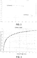
- Fig. 4 is an example of the phase measurement output voltage vs. standoff height from the proposed method and system. It will be understood that the process of mapping a height for a particular laser system relative to a work piece can occur prior to operation, or in a dynamic process cycle using any measurement method known to those of skill in the art including optical, sonic (transducer), or mechanical methods.
- the exemplary system employs a single mapping process for Fig. 4
- a continuous mapping process may be employed by adding a mapping or measuring system to cutting head 3 with a feed back to a process controller for continuous adjustment.
- the proposed method and system will be understood as adaptively dynamic.
- cutting head 3 may include an LPC17xx microcontroller (shown as an LPC1768) to communicate the height and other data back to base station 1 and further process controller 2 via Ethernet.
- An accelerometer is incorporated to separate motion by cutting head 3 from relative motion of work piece 4.
- Base station 1 allows a broad array of analog, digital, and bus input/output to adapt to differing use demands.
- Base station 1 may have one or multiple micro controllers.
- the proposed capacitance sensor, height sensor, or cutting head sensor as 3A employs a two-carrier coherent synthesizer (from a 312.50 MHz system clock) to create two carrier signals equivalent in frequency but different in phase.
- one signal (signal one) is phase-shifted by the 40pF-average capacitive head (noted as a 400-ohm environment at 10MHz) as the capacitance changes by ⁇ 5pF.
- a 1:8 transformer changes this to 50-ohm 320pF.
- the second signal (signal two) is adjusted to a fixed value that creates as close to - 90° between the two carrier signals as can be realized with 0.175° phase steps.
- Phase detection is determined by an AD8302ARUZ gain-phase detector IC shown at having two outputs (as shown). One output of the phase detector is 10mV/° phase. The second output of the phase detector is 10mV/dB relative magnitude.
- the phase detector is adjustable, here having an adjustment range of ⁇ 3.3° around the initial adjustment position and a granularity (into a 3.3V 12-bit ADC known in the art) of 0.003°. Thus making an initial adjustment accuracy of about ⁇ 30 quantization levels and rendering substantial accuracy following adjustment.
- base station 1 via process controller 2, regularly samples the high-gain phase and the relative magnitude (for example by a second microcontroller type LPC1768 known in the art).
- the high-gain phase and relative magnitude are offset by the ⁇ 30 quantization levels of the initial adjustment inaccuracy.
- the high-gain phase and relative magnitude are then compared to tables of height vs. phase and short versus magnitude, and the height and short information are sent out for further use, for a non-limiting example, to a target customer interface at 8.
- proposed system 10 enables adjustment for temperature sensitivity.
- the proposed phase detector system has a temperature coefficient in phase output versus ambient temperature which results in a height error estimated to be ⁇ 10-20 ⁇ m/°C.
- a heater thermal sensor and heater circuit is provided to elevate the proposed phase detector (chip) to around 50°C and to maintain this temperature (although other temperatures may be used without limitation).
- a target set point enables the heater circuit to maintain temperature, for example ⁇ 5°C from a control set point of ⁇ 2.5°C.
- a plurality of cutting heads 3, each with internal sensors and controllers 3A may be jointly operated by a single base station 1 through a production cycle, wherein a work piece may change height substantially through a cycle path.
- a process operation 100 includes a step of inputting initial process cycle data 101 to a process controller 102 in any form noted above and storing selected inputs in a data storage 103 operatively linked with a data calculator 104 all in communication with an input/output feature 105.
- a start operation step 106 begins with a surface approach 107 and confirmation of an initial height 108 and then beginning of a desired laser treatment process (of any kind). Thereafter a continuous height sensing step 109 is performed throughout the continuous process. If system 100 is within range in a determination step 111, the process continues to operate and monitor in step 114 until a completion of cycle 115.
- an out of range step is determined 110 then a cycle of height adjustment 112 and optionally a stop step 113 is initiated to ensure only in range operation.
- input/output step 105 (and thus process controller interaction step 102) is continuously in communication with each operative step in system 100, through a step (via continuous reading step 109) or via a direct link, for example initial height determination step 108.
- data storage step 103 and data calculator step 104 are used continuously throughout each operation cycle as may be modified by an operational control.
- focus is the distance below the nozzle tip that a laser is in focus.
- a focus spot is often desired to be below the surface of a material being cut, and potentially may extend through the material.
- PoE Power over Ethernet
- the proposed system and method may be operated continuously throughout a process cycle and across different work pieces without limitation, and that such understanding of continuous includes pre- and post- laser use, such that the entire system and method will be understood as being operative 'in situ' or throughout the entire use of the system.
- Those of skill in the art, having studied the entire disclosure, will further recognize the broad application of the proposed system and method and that the system and components employed may be modified, removed, substituted, edited, or changed and that all such actions will be understood as within the scope of the invention, as defined by the claims.
- the proposed invention employs one or more microcontrollers or process controllers in operatively preferred locations.
- controllers any number, shape, or location, or type.
- a single controller, in any location may suffice here operatively sufficient communications loops are established between the system components.
- the proposed communication pathways between the cutting head, base station, customer PLC or optional PC's etc. will be understood as exemplary.
- a single base station may suffice, or the proposed system may be substantially autonomous (without continuous signal external to the cutting head), or such communications may be fully remote from the cutting head in communication solely by wireless signal.
Landscapes
- Physics & Mathematics (AREA)
- Optics & Photonics (AREA)
- Engineering & Computer Science (AREA)
- Plasma & Fusion (AREA)
- Mechanical Engineering (AREA)
- General Physics & Mathematics (AREA)
- Laser Beam Processing (AREA)
Claims (14)
- Verfahren zum Verstellen einer Höhe eines Schneidkopfs (3) relativ zu einem Werkstück in einem Laserbearbeitungssystem, umfassend die Schritte: Positionieren eines Kapazitätssensors (13, 15) im Schneidkopf (3), relativ zum Werkstück (4); wobei der Kondensatorsensor (13, 15) eine Düse (15) und einen isolierten Sensorblock (13) enthält, wobei Düse und isolierter Sensorblock des Schneidkopfs (3) einen Kondensator bilden und eine Kapazität haben, die durch den Abstand zum Werkstück (4), das geschnitten wird, beeinflusst ist, wobei zumindest ein erstes Signal mit einer ersten Frequenz an den Sensor (13, 15) angelegt wird; fortlaufendes Überwachen einer Phasenänderung des ersten Signals als eine Kapazitätsänderung im Sensor (13, 15), durch Evaluieren des ersten Signals während einer Verwendung; und Vergleichen der Phasenänderung mit einem gemessenen Höhenreferenzbereich, wodurch die Höhe des Schneidkopfs (3) relativ zum Werkstück bestimmt wird.
- Verfahren zum Verstellen, nach Anspruch 1, ferner umfassend die Schritte:Verstärken des ersten Signals über einen Betriebsbereich; undDigitalisieren des verstärkten ersten Signals, wodurch eine Auflösung der fortlaufend überwachten Phasenänderung verbessert wird.
- Verfahren zum Verstellen, nach Anspruch 1, ferner umfassend die Schritte:Bereitstellen eines Positionierungssystems im Laserbearbeitungssystem, das betriebsfähig ist, den Schneidkopf während der Verwendung relativ zum Werkstück zu positionieren;das Verfahren ferner umfassend den Schritt:Erzeugen eines Signals gemäß der bestimmten Schneidkopfhöhe;Überwachen des Signals relativ zu einem bestimmten Prozessparameter; undfortlaufendes Steuern des Positionierungspositionssystems gemäß dem Signal, um den Schneidkopf während der Verwendung zu positionieren.
- Verfahren zum Verstellen, nach Anspruch 1, ferner umfassend den Schritt:Anlegen eines zweiten Signals an den Kapazitätssensor;wobei das zweite Signal die erste Frequenz hat und in einer festgesetzten Phase ist, die sich vom ersten Signal unterscheidet, und als ein Referenzsignal betriebsfähig ist; undder Schritt zum Überwachen ferner umfassend den Schritt:
Überwachen des zweiten Signals als eine Referenzwellenform. - Verfahren zum Verstellen, nach Anspruch 4, wobei:
das zweite Signal überwacht wird, um eine relative Magnitude einer Phasenänderung des ersten Signals während der Verwendung zu bestimmen. - Verfahren zum Verstellen, nach Anspruch 1, wobei:
nach dem Schritt zum Vergleichen das Verfahren den Schritt umfasst:
Bestimmen eines kalibrierten Bereichs einer Phasenänderung für die erste Frequenz, relativ zu einem gemessenen Bereich einer Höhe des Schneidkopfs zum Werkstück. - Verfahren zum Verstellen, nach Anspruch 4,
der Schritt zum Anlegen eines zweiten Signals ferner umfassend die Schritte:Verstellen des zweiten Signals auf einen festgesetzten Wert von annähernd -90°, dessen Phase sich vom ersten Signal unterscheidet;der Schritt zum Überwachen ferner umfassend den Schritt:Bestimmen einer Phasenverschiebung des ersten Signals als eine Kapazitätsänderung im Kondensatorsensor, durch Evaluieren der Phasenverschiebung des ersten Signals relativ zum festgesetzten Wert, dessen Phase sich vom zweiten Signal unterscheidet; undder Schritt zum Vergleichen ferner umfassend den Schritt von:
Vergleichen der Kapazitätsänderung mit einer abgebildeten Referenz von Höhe gegen Phasenunterschied, wodurch eine relative Höhe zwischen dem Schneidkopf und dem Werkstück während dessen Verwendung bestimmt wird. - Verfahren zum Verstellen, nach Anspruch 7, ferner umfassend die Schritte:Bereitstellen eines Positionierungssystems im Laserbearbeitungssystem, das zum Positionieren des Schneidkopfs relativ zum Werkstück während der Verwendung betriebsfähig ist;das Verfahren ferner umfassend den Schritt:Erzeugen eines Steuersignals gemäß der bestimmten Schneidkopfhöhe;Überwachen des Steuersignals relativ zu einem bestimmten Prozessparameter; undfortlaufendes Steuern des Positionierungspositionssystems gemäß dem Steuersignal, um den Schneidkopf während der Verwendung zu positionieren.
- System zum Verstellen einer Höhe eines Schneidkopfs (3) relativ zu einem Werkstück (4) in einem Laserbearbeitungssystem, umfassend: einen Kapazitätssensor (13, 15) im Schneidkopf (3), relativ zum Werkstück (4); wobei der Kondensatorsensor (13, 15) eine Düse (15) und einen isolierten Sensorblock (13) enthält, wobei Düse und isolierter Sensorblock des Schneidkopfs (3) einen Kondensator bilden und eine Kapazität haben, die durch den Abstand zum Werkstück (4), das geschnitten wird, beeinflusst ist; Mittel zum Anlegen zumindest eines ersten Signals mit einer ersten Frequenz an den Sensor (13, 15); einen Detektor zum fortlaufenden Überwachen einer Phasenänderung des ersten Signals als eine Kapazitätsänderung im Sensor (13, 15), durch Evaluieren des ersten Signals während einer Verwendung; und ein betriebsfähiges Vergleichssystem zum Vergleichen der Phasenänderung mit einem gemessenen Höhenreferenzbereich des Schneidkopfs, wodurch die Höhe des Schneidkopfs (3) relativ zum Werkstück (4) bestimmt wird.
- System zum Verstellen, nach Anspruch 9, ferner umfassend:ein Positionierungssystem im Laserbearbeitungssystem, das betriebsfähig ist, den Schneidkopf während der Verwendung relativ zum Werkstück zu positionieren;einen Generator zum Erzeugen eines Signals gemäß der bestimmten Schneidkopfhöhe;einen Monitor zum Überwachen des Signals relativ zu einem bestimmten Prozessparameter; undein Prozesssteuergerät zum fortlaufenden Steuern des Positionierungspositionssystems gemäß dem Signal, um den Schneidkopf während der Verwendung zu positionieren.
- System zum Verstellen, nach Anspruch 10, ferner umfassend:Mittel zum Anlegen eines zweiten Signals an den Kapazitätssensor;wobei das zweite Signal die erste Frequenz hat und in einer festgesetzten Phase ist, die sich vom ersten Signal unterscheidet, und als ein Referenzsignal betriebsfähig ist; undein Prozesssteuergerät, das zum Überwachen des zweiten Signals als eine Referenzwellenform betriebsfähig ist.
- System zum Verstellen, nach Anspruch 11, wobei:
das Prozesssteuergerät im Schneidkopf und in einer betriebsfähigen Kommunikation mit dem Positionierungssystem ist. - System zum Verstellen, nach Anspruch 11, ferner umfassend:
ein Fernprozesssteuergerät in betriebsfähiger Kommunikation mit dem Kapazitätssensor und dem Laserbearbeitungssystem und dem Positionierungssensor. - System zum Verstellen, nach Anspruch 11, ferner umfassend:
einen Wärmeempfindlichkeitskompensator, der für den Kapazitätssensor betriebsfähig ist.
Applications Claiming Priority (2)
| Application Number | Priority Date | Filing Date | Title |
|---|---|---|---|
| US201161558261P | 2011-11-10 | 2011-11-10 | |
| PCT/US2012/064795 WO2013071283A1 (en) | 2011-11-10 | 2012-11-13 | Dynamic height adjusting system and method for a head assembly of a laser processing system |
Publications (3)
| Publication Number | Publication Date |
|---|---|
| EP2776207A1 EP2776207A1 (de) | 2014-09-17 |
| EP2776207A4 EP2776207A4 (de) | 2015-12-23 |
| EP2776207B1 true EP2776207B1 (de) | 2019-03-27 |
Family
ID=48290673
Family Applications (1)
| Application Number | Title | Priority Date | Filing Date |
|---|---|---|---|
| EP12847744.5A Active EP2776207B1 (de) | 2011-11-10 | 2012-11-13 | Dynamisches höhenverstellungssystem und verfahren für eine kopfanordnung eines laserverarbeitungssystems |
Country Status (6)
| Country | Link |
|---|---|
| US (1) | US20140312018A1 (de) |
| EP (1) | EP2776207B1 (de) |
| JP (1) | JP2015511176A (de) |
| KR (1) | KR20140091047A (de) |
| CN (1) | CN104080570B (de) |
| WO (1) | WO2013071283A1 (de) |
Families Citing this family (21)
| Publication number | Priority date | Publication date | Assignee | Title |
|---|---|---|---|---|
| US9165902B2 (en) * | 2013-12-17 | 2015-10-20 | Kulicke And Soffa Industries, Inc. | Methods of operating bonding machines for bonding semiconductor elements, and bonding machines |
| JP5881912B1 (ja) * | 2014-08-29 | 2016-03-09 | 三菱電機株式会社 | レーザ加工機及び数値制御プログラム作成ソフトウェア |
| CN104400218B (zh) * | 2014-11-28 | 2016-03-23 | 北京大沃科技有限公司 | 一种随动系统 |
| DE102015103047B3 (de) | 2015-03-03 | 2016-08-18 | Trumpf Laser- Und Systemtechnik Gmbh | Initiale Abstandseinnahme für die Laserbearbeitung |
| CN104748843A (zh) * | 2015-04-14 | 2015-07-01 | 福建师范大学 | 基于虚拟仪器的激光器激光功率远程监测方法及系统 |
| PL3103577T3 (pl) * | 2015-06-11 | 2020-04-30 | Matthew Fagan | Układ i sposób do numerycznie sterowanego cięcia plazmowego tkanin metalowych |
| CN105446366B (zh) * | 2015-12-29 | 2018-03-06 | 武汉嘉铭激光有限公司 | 一种基于电容式传感器的位置控制系统及其控制方法 |
| CN106925888A (zh) * | 2015-12-30 | 2017-07-07 | 常州天正工业发展股份有限公司 | 数字化激光切割头 |
| DE102016105560B3 (de) * | 2016-03-24 | 2017-05-11 | Messer Cutting Systems Gmbh | Verfahren und Vorrichtung zur Durchstich-Erkennung beim thermisch unterstützten Durchstechen eines Werkstücks |
| DE102016115415B4 (de) * | 2016-08-19 | 2018-04-12 | Precitec Gmbh & Co. Kg | Isolationsteil zur isolierten Halterung einer elektrisch leitenden Düse und Laserbearbeitungskopf mit einem Sensor zur Erkennung eines derartigen Isolationsteils |
| CN107350633A (zh) * | 2017-06-27 | 2017-11-17 | 安徽联亚智能装备制造有限公司 | 一种基于ZigBee的远程化控制系统 |
| CN109483049B (zh) * | 2018-11-28 | 2020-09-25 | 大族激光科技产业集团股份有限公司 | 激光切割装置及其调焦方法和调焦系统 |
| CN109590619B (zh) * | 2018-12-06 | 2021-08-03 | 大族激光科技产业集团股份有限公司 | 一种切割头高度控制方法及激光切割机 |
| CN110315224A (zh) * | 2019-07-31 | 2019-10-11 | 大族激光科技产业集团股份有限公司 | 一种抗气压干扰的电容调高传感器 |
| CN111774722B (zh) * | 2020-06-30 | 2022-07-01 | 大族激光科技产业集团股份有限公司 | 一种基于激光系统电容传感器反馈信号衰变的智能控制方法 |
| CN112361944A (zh) * | 2020-10-14 | 2021-02-12 | 广东工业大学 | 一种基于纳米电容传感器的无线测量系统及测量方法 |
| CN112440010A (zh) * | 2020-11-30 | 2021-03-05 | 重庆工业赋能创新中心有限公司 | 一种激光切割高度跟随系统及其标定方法 |
| JP7029558B1 (ja) * | 2021-02-26 | 2022-03-03 | Dmg森精機株式会社 | 工作機械および工作機械に着脱可能な工作機械用装置 |
| CN113977103B (zh) * | 2021-11-16 | 2023-08-15 | 上海柏楚电子科技股份有限公司 | 在激光切割中定位金属管材中心方法、装置、设备与介质 |
| CN114535791B (zh) * | 2022-02-28 | 2023-05-26 | 大族激光科技产业集团股份有限公司 | 一种板材激光裁断方法、激光加工设备及存储介质 |
| CN115971691A (zh) * | 2023-03-21 | 2023-04-18 | 济南森峰激光科技股份有限公司 | 一种用于激光切割的电容测距系统及方法 |
Family Cites Families (12)
| Publication number | Priority date | Publication date | Assignee | Title |
|---|---|---|---|---|
| JP2696822B2 (ja) * | 1987-01-22 | 1998-01-14 | ソニー株式会社 | トラツキングサーボ装置 |
| US5136250A (en) * | 1989-04-28 | 1992-08-04 | Seagate Technology, Inc. | Capacitance height gauge |
| US5371336A (en) * | 1991-10-01 | 1994-12-06 | Messer Griesheim Gmbh | Device for contact-free data gathering from a thermal machining system |
| JPH06134589A (ja) * | 1992-10-23 | 1994-05-17 | Murata Mach Ltd | レーザヘッド高さ制御方法 |
| JP2743752B2 (ja) * | 1993-01-14 | 1998-04-22 | 澁谷工業株式会社 | レーザ加工装置 |
| JPH06226480A (ja) * | 1993-02-05 | 1994-08-16 | Murata Mach Ltd | レーザヘッド高さ制御装置 |
| DE4442238C1 (de) | 1994-11-28 | 1996-04-04 | Precitec Gmbh | Verfahren zur thermischen Bearbeitung eines Werkstücks, insbesondere mittels Laserstrahlung |
| GB9712848D0 (en) * | 1997-06-18 | 1997-08-20 | Queensgate Instr Ltd | Capacitance micrometer |
| ATE311956T1 (de) * | 2001-03-08 | 2005-12-15 | Trumpf Werkzeugmaschinen Gmbh | Verfahren und vorrichtung zum brennschneiden von werkstücken |
| CN1981976B (zh) * | 2005-12-12 | 2012-07-18 | 普雷茨特两合公司 | 激光加工设备及运行控制这样一个激光加工设备的方法 |
| JP4828316B2 (ja) * | 2006-06-13 | 2011-11-30 | 三菱電機株式会社 | レーザ加工機用のギャップ検出装置及びレーザ加工システム並びにレーザ加工機用のギャップ検出方法 |
| EP2480859B1 (de) | 2009-09-22 | 2018-07-18 | Laser Mechanisms, Inc. | Schnell reagierendes kapazitives messsystem mit steilflankiger filterunterscheidungsschaltung |
-
2012
- 2012-11-13 EP EP12847744.5A patent/EP2776207B1/de active Active
- 2012-11-13 KR KR1020147015508A patent/KR20140091047A/ko not_active Withdrawn
- 2012-11-13 US US14/356,415 patent/US20140312018A1/en not_active Abandoned
- 2012-11-13 WO PCT/US2012/064795 patent/WO2013071283A1/en not_active Ceased
- 2012-11-13 CN CN201280055431.7A patent/CN104080570B/zh not_active Expired - Fee Related
- 2012-11-13 JP JP2014541402A patent/JP2015511176A/ja active Pending
Non-Patent Citations (1)
| Title |
|---|
| None * |
Also Published As
| Publication number | Publication date |
|---|---|
| WO2013071283A1 (en) | 2013-05-16 |
| CN104080570A (zh) | 2014-10-01 |
| US20140312018A1 (en) | 2014-10-23 |
| EP2776207A4 (de) | 2015-12-23 |
| KR20140091047A (ko) | 2014-07-18 |
| EP2776207A1 (de) | 2014-09-17 |
| JP2015511176A (ja) | 2015-04-16 |
| CN104080570B (zh) | 2016-01-13 |
Similar Documents
| Publication | Publication Date | Title |
|---|---|---|
| EP2776207B1 (de) | Dynamisches höhenverstellungssystem und verfahren für eine kopfanordnung eines laserverarbeitungssystems | |
| CN104303009B (zh) | 用于检查工件的方法和设备 | |
| CN103827623B (zh) | 用于检查工件的方法和设备 | |
| EP2040027B1 (de) | Vorrichtung zum Messen der Wanddicke von Objekten | |
| EP3412383B1 (de) | Vorrichtung zur generativen fertigung eines produkts mit einer kalibriervorrichtung und verfahren zur kalibrierung solch einer vorrichtung | |
| JP5619774B2 (ja) | 接触式の座標位置決め装置の測定サイクルを最適化する方法 | |
| US6553275B1 (en) | In-situ stress monitoring during direct material deposition process | |
| CN105358935A (zh) | 用于检查工件的方法和设备 | |
| JP2017190505A (ja) | 金属粉を供給しながらレーザを照射する加工部を移動させて積層造形を行う積層造形加工方法及び積層造形加工装置 | |
| EP2031347A1 (de) | Verfahren und Vorrichtung zum Messen der Beschichtungsdicke mit einem Laser | |
| CN106660169B (zh) | 用于在激光加工工件时求取间距修正值的方法和相应的激光加工机 | |
| CN104048610A (zh) | 反射式光纤位移传感器现场应用定标的方法和系统 | |
| CN1953848A (zh) | 机器人支持的对测量目标物进行测量的方法 | |
| CN112585483B (zh) | 用于接触触发式坐标机中的测量循环生成的方法、计算机程序和设备 | |
| TW200605966A (en) | Apparatus and method for applying adhesive to a substrate | |
| US11592281B2 (en) | Predetermining the thickness of a coating | |
| GB2429291B (en) | A metrological apparatus | |
| SK288380B6 (sk) | Spôsob vyhodnocovania vzdialenosti technologického nástroja od obrobku a zapojenie na uskutočnenie tohto spôsobu | |
| Barman et al. | Enhancement of accuracy of multi-axis machine tools through error measurement and compensation of errors using laser interferometry technique | |
| Chiniwar et al. | INVESTIGATION OF AUTOMATIC BED LEVELLING SYSTEM FOR FUSED DEPOSITION MODELLING 3D PRINTER MACHINE. | |
| JP6294163B2 (ja) | 半田塗布装置 | |
| WO2012082543A2 (en) | Method for automatic compensation of thermal distortion in a gantry machine | |
| CN207908010U (zh) | 一种送粉器粉桶粉量的检测装置 | |
| CN114563981B (zh) | 一种微小间隙非接触测量调控装置及方法 | |
| CN205156853U (zh) | 一种全自动非接触激光在线检测装置 |
Legal Events
| Date | Code | Title | Description |
|---|---|---|---|
| PUAI | Public reference made under article 153(3) epc to a published international application that has entered the european phase |
Free format text: ORIGINAL CODE: 0009012 |
|
| 17P | Request for examination filed |
Effective date: 20140505 |
|
| AK | Designated contracting states |
Kind code of ref document: A1 Designated state(s): AL AT BE BG CH CY CZ DE DK EE ES FI FR GB GR HR HU IE IS IT LI LT LU LV MC MK MT NL NO PL PT RO RS SE SI SK SM TR |
|
| DAX | Request for extension of the european patent (deleted) | ||
| RA4 | Supplementary search report drawn up and despatched (corrected) |
Effective date: 20151120 |
|
| RIC1 | Information provided on ipc code assigned before grant |
Ipc: B23K 26/38 20140101ALI20151120BHEP Ipc: B23K 26/042 20140101AFI20151120BHEP |
|
| GRAP | Despatch of communication of intention to grant a patent |
Free format text: ORIGINAL CODE: EPIDOSNIGR1 |
|
| STAA | Information on the status of an ep patent application or granted ep patent |
Free format text: STATUS: GRANT OF PATENT IS INTENDED |
|
| INTG | Intention to grant announced |
Effective date: 20180928 |
|
| GRAJ | Information related to disapproval of communication of intention to grant by the applicant or resumption of examination proceedings by the epo deleted |
Free format text: ORIGINAL CODE: EPIDOSDIGR1 |
|
| STAA | Information on the status of an ep patent application or granted ep patent |
Free format text: STATUS: REQUEST FOR EXAMINATION WAS MADE |
|
| GRAP | Despatch of communication of intention to grant a patent |
Free format text: ORIGINAL CODE: EPIDOSNIGR1 |
|
| STAA | Information on the status of an ep patent application or granted ep patent |
Free format text: STATUS: GRANT OF PATENT IS INTENDED |
|
| INTC | Intention to grant announced (deleted) | ||
| GRAS | Grant fee paid |
Free format text: ORIGINAL CODE: EPIDOSNIGR3 |
|
| GRAA | (expected) grant |
Free format text: ORIGINAL CODE: 0009210 |
|
| STAA | Information on the status of an ep patent application or granted ep patent |
Free format text: STATUS: THE PATENT HAS BEEN GRANTED |
|
| INTG | Intention to grant announced |
Effective date: 20190206 |
|
| AK | Designated contracting states |
Kind code of ref document: B1 Designated state(s): AL AT BE BG CH CY CZ DE DK EE ES FI FR GB GR HR HU IE IS IT LI LT LU LV MC MK MT NL NO PL PT RO RS SE SI SK SM TR |
|
| REG | Reference to a national code |
Ref country code: GB Ref legal event code: FG4D |
|
| REG | Reference to a national code |
Ref country code: CH Ref legal event code: EP |
|
| REG | Reference to a national code |
Ref country code: AT Ref legal event code: REF Ref document number: 1112484 Country of ref document: AT Kind code of ref document: T Effective date: 20190415 |
|
| REG | Reference to a national code |
Ref country code: IE Ref legal event code: FG4D |
|
| REG | Reference to a national code |
Ref country code: DE Ref legal event code: R096 Ref document number: 602012058400 Country of ref document: DE |
|
| PG25 | Lapsed in a contracting state [announced via postgrant information from national office to epo] |
Ref country code: SE Free format text: LAPSE BECAUSE OF FAILURE TO SUBMIT A TRANSLATION OF THE DESCRIPTION OR TO PAY THE FEE WITHIN THE PRESCRIBED TIME-LIMIT Effective date: 20190327 Ref country code: FI Free format text: LAPSE BECAUSE OF FAILURE TO SUBMIT A TRANSLATION OF THE DESCRIPTION OR TO PAY THE FEE WITHIN THE PRESCRIBED TIME-LIMIT Effective date: 20190327 Ref country code: NO Free format text: LAPSE BECAUSE OF FAILURE TO SUBMIT A TRANSLATION OF THE DESCRIPTION OR TO PAY THE FEE WITHIN THE PRESCRIBED TIME-LIMIT Effective date: 20190627 Ref country code: LT Free format text: LAPSE BECAUSE OF FAILURE TO SUBMIT A TRANSLATION OF THE DESCRIPTION OR TO PAY THE FEE WITHIN THE PRESCRIBED TIME-LIMIT Effective date: 20190327 |
|
| REG | Reference to a national code |
Ref country code: NL Ref legal event code: MP Effective date: 20190327 |
|
| PG25 | Lapsed in a contracting state [announced via postgrant information from national office to epo] |
Ref country code: NL Free format text: LAPSE BECAUSE OF FAILURE TO SUBMIT A TRANSLATION OF THE DESCRIPTION OR TO PAY THE FEE WITHIN THE PRESCRIBED TIME-LIMIT Effective date: 20190327 Ref country code: HR Free format text: LAPSE BECAUSE OF FAILURE TO SUBMIT A TRANSLATION OF THE DESCRIPTION OR TO PAY THE FEE WITHIN THE PRESCRIBED TIME-LIMIT Effective date: 20190327 Ref country code: GR Free format text: LAPSE BECAUSE OF FAILURE TO SUBMIT A TRANSLATION OF THE DESCRIPTION OR TO PAY THE FEE WITHIN THE PRESCRIBED TIME-LIMIT Effective date: 20190628 Ref country code: LV Free format text: LAPSE BECAUSE OF FAILURE TO SUBMIT A TRANSLATION OF THE DESCRIPTION OR TO PAY THE FEE WITHIN THE PRESCRIBED TIME-LIMIT Effective date: 20190327 Ref country code: BG Free format text: LAPSE BECAUSE OF FAILURE TO SUBMIT A TRANSLATION OF THE DESCRIPTION OR TO PAY THE FEE WITHIN THE PRESCRIBED TIME-LIMIT Effective date: 20190627 Ref country code: RS Free format text: LAPSE BECAUSE OF FAILURE TO SUBMIT A TRANSLATION OF THE DESCRIPTION OR TO PAY THE FEE WITHIN THE PRESCRIBED TIME-LIMIT Effective date: 20190327 |
|
| REG | Reference to a national code |
Ref country code: AT Ref legal event code: MK05 Ref document number: 1112484 Country of ref document: AT Kind code of ref document: T Effective date: 20190327 |
|
| PG25 | Lapsed in a contracting state [announced via postgrant information from national office to epo] |
Ref country code: PT Free format text: LAPSE BECAUSE OF FAILURE TO SUBMIT A TRANSLATION OF THE DESCRIPTION OR TO PAY THE FEE WITHIN THE PRESCRIBED TIME-LIMIT Effective date: 20190727 Ref country code: AL Free format text: LAPSE BECAUSE OF FAILURE TO SUBMIT A TRANSLATION OF THE DESCRIPTION OR TO PAY THE FEE WITHIN THE PRESCRIBED TIME-LIMIT Effective date: 20190327 Ref country code: ES Free format text: LAPSE BECAUSE OF FAILURE TO SUBMIT A TRANSLATION OF THE DESCRIPTION OR TO PAY THE FEE WITHIN THE PRESCRIBED TIME-LIMIT Effective date: 20190327 Ref country code: CZ Free format text: LAPSE BECAUSE OF FAILURE TO SUBMIT A TRANSLATION OF THE DESCRIPTION OR TO PAY THE FEE WITHIN THE PRESCRIBED TIME-LIMIT Effective date: 20190327 Ref country code: RO Free format text: LAPSE BECAUSE OF FAILURE TO SUBMIT A TRANSLATION OF THE DESCRIPTION OR TO PAY THE FEE WITHIN THE PRESCRIBED TIME-LIMIT Effective date: 20190327 Ref country code: IT Free format text: LAPSE BECAUSE OF FAILURE TO SUBMIT A TRANSLATION OF THE DESCRIPTION OR TO PAY THE FEE WITHIN THE PRESCRIBED TIME-LIMIT Effective date: 20190327 Ref country code: EE Free format text: LAPSE BECAUSE OF FAILURE TO SUBMIT A TRANSLATION OF THE DESCRIPTION OR TO PAY THE FEE WITHIN THE PRESCRIBED TIME-LIMIT Effective date: 20190327 Ref country code: SK Free format text: LAPSE BECAUSE OF FAILURE TO SUBMIT A TRANSLATION OF THE DESCRIPTION OR TO PAY THE FEE WITHIN THE PRESCRIBED TIME-LIMIT Effective date: 20190327 |
|
| PG25 | Lapsed in a contracting state [announced via postgrant information from national office to epo] |
Ref country code: PL Free format text: LAPSE BECAUSE OF FAILURE TO SUBMIT A TRANSLATION OF THE DESCRIPTION OR TO PAY THE FEE WITHIN THE PRESCRIBED TIME-LIMIT Effective date: 20190327 Ref country code: SM Free format text: LAPSE BECAUSE OF FAILURE TO SUBMIT A TRANSLATION OF THE DESCRIPTION OR TO PAY THE FEE WITHIN THE PRESCRIBED TIME-LIMIT Effective date: 20190327 |
|
| PG25 | Lapsed in a contracting state [announced via postgrant information from national office to epo] |
Ref country code: AT Free format text: LAPSE BECAUSE OF FAILURE TO SUBMIT A TRANSLATION OF THE DESCRIPTION OR TO PAY THE FEE WITHIN THE PRESCRIBED TIME-LIMIT Effective date: 20190327 Ref country code: IS Free format text: LAPSE BECAUSE OF FAILURE TO SUBMIT A TRANSLATION OF THE DESCRIPTION OR TO PAY THE FEE WITHIN THE PRESCRIBED TIME-LIMIT Effective date: 20190727 |
|
| REG | Reference to a national code |
Ref country code: DE Ref legal event code: R097 Ref document number: 602012058400 Country of ref document: DE |
|
| PG25 | Lapsed in a contracting state [announced via postgrant information from national office to epo] |
Ref country code: DK Free format text: LAPSE BECAUSE OF FAILURE TO SUBMIT A TRANSLATION OF THE DESCRIPTION OR TO PAY THE FEE WITHIN THE PRESCRIBED TIME-LIMIT Effective date: 20190327 |
|
| PLBE | No opposition filed within time limit |
Free format text: ORIGINAL CODE: 0009261 |
|
| STAA | Information on the status of an ep patent application or granted ep patent |
Free format text: STATUS: NO OPPOSITION FILED WITHIN TIME LIMIT |
|
| PG25 | Lapsed in a contracting state [announced via postgrant information from national office to epo] |
Ref country code: SI Free format text: LAPSE BECAUSE OF FAILURE TO SUBMIT A TRANSLATION OF THE DESCRIPTION OR TO PAY THE FEE WITHIN THE PRESCRIBED TIME-LIMIT Effective date: 20190327 |
|
| 26N | No opposition filed |
Effective date: 20200103 |
|
| PG25 | Lapsed in a contracting state [announced via postgrant information from national office to epo] |
Ref country code: TR Free format text: LAPSE BECAUSE OF FAILURE TO SUBMIT A TRANSLATION OF THE DESCRIPTION OR TO PAY THE FEE WITHIN THE PRESCRIBED TIME-LIMIT Effective date: 20190327 |
|
| REG | Reference to a national code |
Ref country code: CH Ref legal event code: PL |
|
| PG25 | Lapsed in a contracting state [announced via postgrant information from national office to epo] |
Ref country code: LI Free format text: LAPSE BECAUSE OF NON-PAYMENT OF DUE FEES Effective date: 20191130 Ref country code: CH Free format text: LAPSE BECAUSE OF NON-PAYMENT OF DUE FEES Effective date: 20191130 Ref country code: LU Free format text: LAPSE BECAUSE OF NON-PAYMENT OF DUE FEES Effective date: 20191113 Ref country code: MC Free format text: LAPSE BECAUSE OF FAILURE TO SUBMIT A TRANSLATION OF THE DESCRIPTION OR TO PAY THE FEE WITHIN THE PRESCRIBED TIME-LIMIT Effective date: 20190327 |
|
| REG | Reference to a national code |
Ref country code: BE Ref legal event code: MM Effective date: 20191130 |
|
| GBPC | Gb: european patent ceased through non-payment of renewal fee |
Effective date: 20191113 |
|
| PG25 | Lapsed in a contracting state [announced via postgrant information from national office to epo] |
Ref country code: FR Free format text: LAPSE BECAUSE OF NON-PAYMENT OF DUE FEES Effective date: 20191130 Ref country code: IE Free format text: LAPSE BECAUSE OF NON-PAYMENT OF DUE FEES Effective date: 20191113 Ref country code: GB Free format text: LAPSE BECAUSE OF NON-PAYMENT OF DUE FEES Effective date: 20191113 |
|
| PG25 | Lapsed in a contracting state [announced via postgrant information from national office to epo] |
Ref country code: BE Free format text: LAPSE BECAUSE OF NON-PAYMENT OF DUE FEES Effective date: 20191130 |
|
| PG25 | Lapsed in a contracting state [announced via postgrant information from national office to epo] |
Ref country code: CY Free format text: LAPSE BECAUSE OF FAILURE TO SUBMIT A TRANSLATION OF THE DESCRIPTION OR TO PAY THE FEE WITHIN THE PRESCRIBED TIME-LIMIT Effective date: 20190327 |
|
| PG25 | Lapsed in a contracting state [announced via postgrant information from national office to epo] |
Ref country code: MT Free format text: LAPSE BECAUSE OF FAILURE TO SUBMIT A TRANSLATION OF THE DESCRIPTION OR TO PAY THE FEE WITHIN THE PRESCRIBED TIME-LIMIT Effective date: 20190327 Ref country code: HU Free format text: LAPSE BECAUSE OF FAILURE TO SUBMIT A TRANSLATION OF THE DESCRIPTION OR TO PAY THE FEE WITHIN THE PRESCRIBED TIME-LIMIT; INVALID AB INITIO Effective date: 20121113 |
|
| PG25 | Lapsed in a contracting state [announced via postgrant information from national office to epo] |
Ref country code: MK Free format text: LAPSE BECAUSE OF FAILURE TO SUBMIT A TRANSLATION OF THE DESCRIPTION OR TO PAY THE FEE WITHIN THE PRESCRIBED TIME-LIMIT Effective date: 20190327 |
|
| P01 | Opt-out of the competence of the unified patent court (upc) registered |
Effective date: 20230516 |
|
| PGFP | Annual fee paid to national office [announced via postgrant information from national office to epo] |
Ref country code: DE Payment date: 20241001 Year of fee payment: 13 |