EP2776341B1 - Kapsel zur herstellung eines getränks mit verbesserten dichtungsmitteln - Google Patents
Kapsel zur herstellung eines getränks mit verbesserten dichtungsmitteln Download PDFInfo
- Publication number
- EP2776341B1 EP2776341B1 EP12783921.5A EP12783921A EP2776341B1 EP 2776341 B1 EP2776341 B1 EP 2776341B1 EP 12783921 A EP12783921 A EP 12783921A EP 2776341 B1 EP2776341 B1 EP 2776341B1
- Authority
- EP
- European Patent Office
- Prior art keywords
- capsule
- sealing member
- liquid inlet
- upper wall
- liquid
- Prior art date
- Legal status (The legal status is an assumption and is not a legal conclusion. Google has not performed a legal analysis and makes no representation as to the accuracy of the status listed.)
- Active
Links
Images

Classifications
-
- A—HUMAN NECESSITIES
- A47—FURNITURE; DOMESTIC ARTICLES OR APPLIANCES; COFFEE MILLS; SPICE MILLS; SUCTION CLEANERS IN GENERAL
- A47J—KITCHEN EQUIPMENT; COFFEE MILLS; SPICE MILLS; APPARATUS FOR MAKING BEVERAGES
- A47J31/00—Apparatus for making beverages
- A47J31/40—Beverage-making apparatus with dispensing means for adding a measured quantity of ingredients, e.g. coffee, water, sugar, cocoa, milk, tea
- A47J31/407—Beverage-making apparatus with dispensing means for adding a measured quantity of ingredients, e.g. coffee, water, sugar, cocoa, milk, tea with ingredient-containing cartridges; Cartridge-perforating means
-
- B—PERFORMING OPERATIONS; TRANSPORTING
- B65—CONVEYING; PACKING; STORING; HANDLING THIN OR FILAMENTARY MATERIAL
- B65D—CONTAINERS FOR STORAGE OR TRANSPORT OF ARTICLES OR MATERIALS, e.g. BAGS, BARRELS, BOTTLES, BOXES, CANS, CARTONS, CRATES, DRUMS, JARS, TANKS, HOPPERS, FORWARDING CONTAINERS; ACCESSORIES, CLOSURES, OR FITTINGS THEREFOR; PACKAGING ELEMENTS; PACKAGES
- B65D85/00—Containers, packaging elements or packages, specially adapted for particular articles or materials
- B65D85/70—Containers, packaging elements or packages, specially adapted for particular articles or materials for materials not otherwise provided for
- B65D85/804—Disposable containers or packages with contents which are mixed, infused or dissolved in situ, i.e. without having been previously removed from the package
- B65D85/8043—Packages adapted to allow liquid to pass through the contents
- B65D85/8055—Means for influencing the liquid flow inside the package
-
- B—PERFORMING OPERATIONS; TRANSPORTING
- B65—CONVEYING; PACKING; STORING; HANDLING THIN OR FILAMENTARY MATERIAL
- B65D—CONTAINERS FOR STORAGE OR TRANSPORT OF ARTICLES OR MATERIALS, e.g. BAGS, BARRELS, BOTTLES, BOXES, CANS, CARTONS, CRATES, DRUMS, JARS, TANKS, HOPPERS, FORWARDING CONTAINERS; ACCESSORIES, CLOSURES, OR FITTINGS THEREFOR; PACKAGING ELEMENTS; PACKAGES
- B65D85/00—Containers, packaging elements or packages, specially adapted for particular articles or materials
- B65D85/70—Containers, packaging elements or packages, specially adapted for particular articles or materials for materials not otherwise provided for
- B65D85/804—Disposable containers or packages with contents which are mixed, infused or dissolved in situ, i.e. without having been previously removed from the package
- B65D85/8043—Packages adapted to allow liquid to pass through the contents
- B65D85/8049—Details of the inlet
-
- B—PERFORMING OPERATIONS; TRANSPORTING
- B65—CONVEYING; PACKING; STORING; HANDLING THIN OR FILAMENTARY MATERIAL
- B65D—CONTAINERS FOR STORAGE OR TRANSPORT OF ARTICLES OR MATERIALS, e.g. BAGS, BARRELS, BOTTLES, BOXES, CANS, CARTONS, CRATES, DRUMS, JARS, TANKS, HOPPERS, FORWARDING CONTAINERS; ACCESSORIES, CLOSURES, OR FITTINGS THEREFOR; PACKAGING ELEMENTS; PACKAGES
- B65D85/00—Containers, packaging elements or packages, specially adapted for particular articles or materials
- B65D85/70—Containers, packaging elements or packages, specially adapted for particular articles or materials for materials not otherwise provided for
- B65D85/804—Disposable containers or packages with contents which are mixed, infused or dissolved in situ, i.e. without having been previously removed from the package
- B65D85/8043—Packages adapted to allow liquid to pass through the contents
- B65D85/8052—Details of the outlet
-
- B—PERFORMING OPERATIONS; TRANSPORTING
- B65—CONVEYING; PACKING; STORING; HANDLING THIN OR FILAMENTARY MATERIAL
- B65D—CONTAINERS FOR STORAGE OR TRANSPORT OF ARTICLES OR MATERIALS, e.g. BAGS, BARRELS, BOTTLES, BOXES, CANS, CARTONS, CRATES, DRUMS, JARS, TANKS, HOPPERS, FORWARDING CONTAINERS; ACCESSORIES, CLOSURES, OR FITTINGS THEREFOR; PACKAGING ELEMENTS; PACKAGES
- B65D85/00—Containers, packaging elements or packages, specially adapted for particular articles or materials
- B65D85/70—Containers, packaging elements or packages, specially adapted for particular articles or materials for materials not otherwise provided for
- B65D85/804—Disposable containers or packages with contents which are mixed, infused or dissolved in situ, i.e. without having been previously removed from the package
- B65D85/8043—Packages adapted to allow liquid to pass through the contents
- B65D85/8064—Sealing means for the interface with the processing machine
Definitions
- the present invention relates to the field of the preparation of a beverage from a beverage substance contained in a capsule by passing a liquid through the substance using centrifugal forces.
- the present invention relates to a capsule with enhanced sealing means for preventing liquid from bypassing an ingredients compartment of the capsule during beverage preparation, according to claim 1.
- Capsules containing beverage ingredients and designed for producing a beverage in a beverage preparation device upon liquid injection into the capsules and by rotating the capsules around a central axis in the device are known.
- the general principle consists in preparing a beverage by passing a liquid through beverage ingredients contained in the capsule using centrifugal forces.
- liquid is usually injected in a central inlet area of the capsule before and/or during rotation of the capsule in order to make the liquid interact with the ingredients provided in the capsule, thereby forming a beverage such as coffee, ground coffee, tea or the like.
- the resulting beverage is then allowed to exit the capsule by means of at least one outlet aperture provided at a portion arranged radially outside of (and at distance from) the central inlet area of the capsule.
- a capsule for preparing a beverage or liquid food and a system using centrifugal forces is for example described in WO2010/063644 .
- the capsule is formed of a rotational symmetric body containing beverage ingredients such as coffee powder, the body comprising a side wall, a bottom wall, an opening, a flange-like rim and an upper wall attached to the flange-like rim of the body and covering the opening of the body.
- the upper wall of the capsule comprises a central inlet portion and a peripheral outlet portion between the inlet portion and the flange-like rim, wherein the peripheral outlet portion is opened or openable to allow beverage to leave the capsule under the centrifugal forces, and wherein the capsule is configured in the central inlet portion to provide liquid tightness between the liquid inlet and the surface of an injection needle or lance of the beverage production device to prevent liquid from leaking from the inside towards the outside of the capsule.
- liquid tightness at the inlet site of the capsule is established during beverage preparation by means of a soft layer or pad of the upper wall of the capsule sealingly contacting the outer surfaces of the injection member (i.e., an injection needle or lance).
- WO2008148646 relates to a beverage capsule for a beverage production device comprising a lid with an inlet port and a tubular inlet portion which serves for ensuring water is guided towards the direction of the bottom of the capsule to ensure complete wetting of the substance in the enclosure and so reduce risk of leaving for example "dry powder spots".
- tubular inlet portion has no tightness function at the inlet site of the capsule but simply a liquid-funnelling function inside the capsule to ensure that water fully spread inside the product ingredients such as coffee powder.
- the known capsules also suffer the drawback that due to the provided sealing engagement between the outer surface of the injection member and a portion of the upper wall of the capsule, the detachment of the capsule from the injection member after the beverage preparation is relatively complicated.
- the known capsules tend to stick to the outer surface of the injection member of the device after the beverage preparation. This problem may even become worse if the injection member deviates from its originally intended position in which the injection member is perfectly aligned with the rotational axis of the capsule.
- a capsule is sought-after which enables the effective sealing of the liquid inlet site and the beverage preparation device independent on the position and geometric shape of the injection member.
- it is desired to provide a sealing engagement that facilitates the removal of the capsule from the device after the beverage preparation.
- the present invention seeks to address the above-described problems.
- the invention also aims at other objects and particularly the solution of other problems as will appear in the rest of the present description.
- the present invention relates to a capsule according to claim 1.
- the sealing member is protruding from the upper wall to the outside, i.e. in a direction directed away from the interior of the capsule respectively from the ingredients compartment in which the beverage ingredients are provided.
- the upper wall can be essentially formed as a disc-shaped member arranged essentially perpendicular to a rotational axis of the capsule.
- the sealing member of the capsule is preferably designed to be contacted respectively engaged by a dedicated rotary engagement member of the beverage preparation device, wherein said rotary engagement member is provided radially outside and thus, at the circumference of the injection member of the device.
- the engagement member is preferably of essential convex and/or pyramidal geometric form.
- a sealing member is provided in an off-centred position relative to the surface of the injection member through the liquid inlet.
- the liquid inlet of the capsule is preferably an open or openable central portion of the upper wall into which the injection member of the beverage preparation device may be inserted.
- the inlet is preferably of circular form and provided with an inner diameter that is preferably greater than or equal to the outer diameter of the injection member.
- the liquid inlet may be provided with a membrane that is designed for being opened, preferably pierced, by means of the injection member of the beverage preparation device.
- a recess is formed between the protruding sealing member and the central liquid inlet.
- an effective sealing of the liquid inlet of the capsule during beverage preparation is obtainable without a physical contact of the sealing member and the injection member. Accordingly, an effective sealing of the inlet site of the capsule is provided independent of the geometric shape and/or a deviation from the originally intended position of the injection member. Moreover, a facilitated removal or ejection of the capsule after the beverage preparation from the injection member is enabled.
- the sealing member is preferably continuously formed about the central liquid inlet of the upper wall of the capsule when seen in a top view onto the upper wall.
- the sealing member preferably comprises an essentially circular or tubular form having an inner diameter that is larger than the maximum diameter of the liquid inlet respectively the maximum diameter of a dedicated injection member of the beverage preparation device.
- the sealing member is not necessarily strictly concentric relative to the liquid inlet but may be slightly eccentrically positioned about and at a distance from the liquid inlet.
- the sealing member has preferably a continuously closed cross-section in transversal direction such as circular, oval, ovoid, squared, rectangular, and polygonal.
- a concentric centred position of a sealing member which is circular in transversal cross section is preferred.
- the sealing member may as well be intermittently respectively discontinuously arranged about the circumference of the central liquid inlet.
- the sealing member may comprise at least two different portions arranged with respect to each other such as to constitute e.g. a labyrinth structure when seen in top view onto the upper wall. Accordingly, liquid trying to bypass the liquid inlet towards a peripheral portion of the upper wall is forced to meander about/through interstitial spaces provided between the at least two different portions of the sealing member.
- the sealing member is preferably protruding from the upper wall of the capsule in a direction essentially parallel to a rotational axis of the capsule.
- the sealing member may as well protrude in a direction inclined about +/- 5° to 45° from the rotational axis of the capsule.
- the height to which the sealing member protrudes from the outer surface of the upper wall is preferably between 1.5 and 20 mm, more preferably between 2 and 15 mm.
- the sealing member may be arranged within a recess formed by the upper wall with respect to the outer flange-like rim portion of the capsule.
- the height to which the sealing member protrudes from the upper wall is preferably equal to or less than the depth of the recess formed by the upper wall and measured from an upper surface of the flange-like rim portion.
- the sealing member is preferably designed for being deflected and/or compressed.
- the deflection and/or compression may in particular be due to a force exerted onto the sealing member preferably in an axially direction, i.e. in a direction parallel to the rotational axis of the capsule.
- the sealing member according to the invention preferably comprises at least one protrusion and/or recession when seen in sectional side view of the capsule.
- the sealing member comprises at least two, more preferably a plurality of concentrically arranged sealing portions such as e.g. flexible and/or resilient sealing lips protruding from the upper wall member and having recessions arranged between the respective sealing portions.
- the at least one recession arranged between different sealing portions of the sealing member may be designed for being closed upon engagement of the sealing member by means of the rotary engagement member of the beverage preparation device. Accordingly, the recessions may be designed for supporting the different portions of the sealing member against a further deflection when compressive forces are exerted onto the sealing member.
- the at least one recession of the sealing member may as well be designed for supporting additional portions of the sealing member such as for example an engagement portion of different shape and/or material as will be described below.
- the sealing member comprises at least two portions of different geometrical shapes and/or materials.
- the sealing member preferably comprises a lower base portion directly connected to the upper wall and an upper engagement portion that is provided preferably at an end or distal portion of the sealing member and which is intended to be directly contacted by the respective surface of the rotary engagement member of the beverage preparation device.
- the lower base portion of the sealing member is preferably integrally formed with the upper wall of the capsule. Accordingly, the lower base portion of the sealing member is made of the same material as the upper wall, preferably plastics, bio-plastic or any biodegradable material.
- the lower base portion is preferably protruding from the upper wall of the capsule with constant thickness.
- the lower base portion has preferably a rectangular cross-sectional profile.
- the lower base portion may as well have a different cross-sectional profile such as of a cubical, a triangular or a truncated cone-shaped form.
- the upper engagement portion is preferably a soft and/or resilient portion that is fixedly connected to the lower base portion of the sealing member or integrally formed with said lower base portion.
- the softness and/or the resiliency of the engagement portion of the sealing member are preferably due to the material and/or geometrical shape of the engagement portion.
- the upper engagement portion may be a layer of different material connected to the base portion of the sealing member.
- the upper engagement portion may be connected to the base portion by means of glue or a welding technique for example.
- the upper engagement portion may be connected to an upper surface of the base portion. However, the upper engagement portion may as well be connected to a recession formed within the base portion of the sealing member. Thereby, the upper engagement portion is preferably protruding from the recession to a height that is greater than the depth of the recession.
- the engagement portion is preferably provided in a specific contact area of the sealing member that is intended to be engaged by means of the rotary engagement member of the beverage preparation device.
- the outer surface of the lower base portion of the sealing member may be covered to a large extent or completely covered with the engagement portion of the sealing member.
- the material of the engagement portion is preferably chosen to be softer compared to the material of the base portion of the sealing member.
- the engagement portion may be made of a plastic such as high-density polyethylene or low-density polyethylene.
- the engagement portion may as well be a liquid resin material applied in liquid form the base portion of the sealing member and then cured.
- a stable support of the protruding sealing member is provided by means of the relatively rigid base portion, while at the same time effective sealing between the capsule and the rotary engagement member may be provided by means of the relatively soft engagement portion.
- the engagement portion may comprise a geometric shape designed to support the resiliency respectively the flexibility of the engagement portion with respect to the base portion of the sealing member.
- the engagement portion may for example comprise a reduced thickness compared to the base portion on which it is arranged.
- the engagement portion may comprise a radially outwardly or inwardly bent sealing lip. Thereby, the engagement portion may be integrally formed or formed as an additional part to the base portion of the sealing member.
- the engagement portion if a force is exerted on the sealing member, the engagement portion will be compressed respectively deflected relatively easy compared to the base portion of the sealing member.
- the surface of the engagement portion may optimally adapt to the outer surface of the rotary engagement member of the beverage preparation device and thus, an enhanced sealing engagement is obtained.
- At least the engagement portion of the sealing member is of material designed to soften in presence of hot water to increase the liquid-tight sealing engagement between the liquid inlet and the outlet apertures.
- the present invention relates to a beverage preparation system comprising a capsule as aforementioned and a beverage preparation device comprising a liquid injection member for supplying liquid to the capsule and a rotary engagement member positioned about the liquid injected member and designed for interacting with the sealing member of the capsule for sealing the liquid inlet from the outlet apertures of the capsule.
- the rotary engagement member is arranged radially outside of the liquid injection member and is preferably convex- and/or pyramidal-shaped.
- the present invention relates to a capsule kit comprising the features of claim 14.
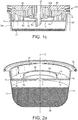
- FIG. 1 a shows a preferred embodiment of the capsule 1 according to the invention.
- the capsule 1 comprises a side wall 2a, a bottom wall 2b and a flange-like rim portion 2c which protrudes from the side wall 2a in a plane essentially perpendicular to a rotational axis Z of the capsule 1.
- the side wall 2a, the bottom wall 2b and the flange-like rim portion 2c are preferably integrally formed and constitute a body 2 of the capsule 1.
- the capsule 1 further comprises an upper wall or lid member 3 that is connected or connectable to the side wall 2a and/or to the flange-like rim 2c of the capsule body 2.
- the upper wall 3 may be arranged to form a recess 12 within the capsule 1 in which a part of the beverage preparation device 20 such as a support member or an engagement member 22 circumferentially arranged to an injection member 21 may be accommodated.
- Said recess 12 is of depth t which lies preferably between 3 and 20mm, more preferably between 5 and 15 mm. It should be noted that the flange-like rim 2c could be part of the lid member instead of being part of the body 2.
- the upper wall 3 and the body 2 of the capsule 1 enclose an ingredients compartment 11 in which beverage ingredients such as ground coffee or the like are provided.
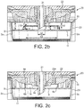
- the upper wall 3 comprises a central liquid inlet 4 that is preferably an open or openable circular aperture designed for accommodating the liquid injection member 21 of the device.
- the liquid inlet 4 may be covered by a sealing membrane (not shown) applied to the upper membrane 3 or to the flange-like rim portion 2c.
- the liquid inlet 4 may as well be constituted by a piercable portion of the upper wall 3 which is designed to be opened by the liquid injection member 21.
- the upper wall 3 further comprises peripheral outlet apertures 5 for the release of the beverage during the rotation of the capsule, which are arranged in a peripheral portion 3b of the upper wall 3.
- annular portion 3a is arranged at which a sealing member 6 of the capsule 1 is provided.
- This intermediate annular portion of the upper wall is preferably free of apertures.
- the sealing member 6 is preferably integrally formed with the upper wall 3.
- the sealing member 6 may as well be provided as an additional element which is designed to be mechanically connected to the upper wall 3. Thereby, the sealing member 6 may be designed to be screwed or plugged such as press-fitted into dedicated connection means provided at upper wall 3.
- the sealing member 6 protrudes from the outer surface 3c of the upper wall 3 to an overall height h that is preferably lower than the depth t of recess 12.
- the height h is preferably between 1 and 20 mm, more preferably between 2 and 15mm.
- the height h and depth t are measured from the outer surface 3c of the upper wall 3 in a direction parallel to the rotational axis Z of the capsule 1.
- the sealing member 6 comprises at least two portions 6a, 6b which differ in material and/or geometrical shape.
- the sealing member 6 comprises a lower base portion 6a that is preferably integrally formed with the upper wall 3.
- the base portion 6a is of relatively rigid material such as e.g. plastic or starch-based polymer.
- the base portion 6a preferably comprises an essentially tubular geometric form and protrudes from the outer surface 3c of the upper wall 3 to a height h1 .
- the height h1 lies preferably between 1 and 15 mm, more preferably between 1 and 10 mm.
- an engagement portion 6b of the sealing member 6 is provided which is softer and/or more flexible.
- the engagement portion 6b may be formed of the same material as the material of the base portion 6a in which case the flexibility is obtained by a thinner or more elongated profile. In such case, the engagement portion 6b is made integral with the base portion 6a.
- the engagement portion 6b may alternatively be formed of a softer and/or more flexible material than the material of the base portion 6a.
- the engagement portion 6b may be formed by over-moulding of a softer polymer onto a harder plastic constituting the base portion 6a.
- the engagement portion 6b may also be connected to the base portion 6a by means of a glue or a welding technique.
- the engagement portion 6b may as well be provided or press-fitted into a provided recess of the base portion 6a.
- the engagement portion may for instance be a rubber or silicone insert.
- the engagement portion 6b protrudes from the base portion 6a to a height h2 that is preferably between 0.2 and 3 mm, more preferably between 0.5 and 2.5 mm.
- the inner diameter d2 of the liquid inlet 4 is preferably equal or slightly larger than the outer diameter d1 of the injection member 21.
- the inner diameter d3 of the circumferentially arranged sealing member 6 is chosen to be much greater than the outer diameter d1 of the injection member 21 of the beverage preparation device and than the inner diameter d2 .
- diameter d3 is at least 1.5 times, more preferably at least 2 times larger than diameter d2 .
- a sealing compartment 14 is formed by means of the outer surface 3c of the upper wall 3, the inner surface 6c of the sealing member 6 and the lower surface 22a of a dedicated rotary engagement member 22 of the beverage preparation device 20.
- a sealing engagement is provided between the engagement portion 6b of the sealing member 6 and the lower surface 22a of the engagement member 23 due to the axial closure force of the device exerted in a direction essentially parallel to the rotational axis Z of the capsule 1.
- the rotary engagement member 22 and the injection member 21 are arranged to be movable with respect to the engagement member 23 in a direction essentially parallel to the rotational axis Z of the capsule 1 in order to enable a provision of the capsule 1 to the device, respectively, an ejection of the capsule 1 from the device.
- the engagement member 23 is preferably connected to a rotary drive means such as an electric motor that enables to rotate the capsule 1 about its rotational axis Z within the device.
- the device 20 comprises at least a liquid supply, a liquid heating means and a pump connected to the injection member 21. Accordingly, the device 20 is designed to provide heated, pressurized liquid such as water into the capsule 1 by means of the injection member 21.
- liquid is provided into the capsule 1 by means of the injection member 21 via liquid inlet 4.
- the capsule 1 is driven about its rotational axis Z in order to force liquid to traverse the capsule 1 by the forces of centrifugation. Consequently, such liquid is made to interact with the ingredients provided in the capsule and, as a result, a beverage is formed by the mixture of liquid-solid or the liquid extract which can leave the capsule by means of the peripheral outlet apertures 5.
- the liquid provided by means of the injection member 21 is prevented from bypassing the interior of the capsule 1 as the liquid flow path from the liquid inlet 4 to the peripheral outlet apertures 5 outside of the capsule 1 is effectively sealed or at least significantly hindered by means of the sealing member 6 arranged there between.
- the engagement portion 6b is integrally formed with the base portion 6a. Thereby, the engagement portion 6b is geometrically shaped to provide a relatively softer and/or more flexible end portion which may be easily be compressed and/or deflected upon engagement of the capsule 1 within the beverage preparation device. For this, the engagement portion 6b may form a sealing lip or a plurality of sealing lips.
- the engagement portion 6b is preferably of a relatively smaller thickness t2 which lies between 0.1 and 1.5 mm, more preferably between 0.3 and 1.2mm. Moreover, the thickness t2 preferably decreases from the base to a distal portion respectively outer edge 14 of the engagement portion 6b.
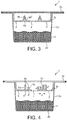
- Figure 3 relates to another preferred embodiment of a capsule 1 according to the invention, wherein the base portion 6a of the sealing member 6 is integrally formed with the upper wall 3.
- the base portion 6a is of essentially triangular cross-sectional form. Accordingly, the thickness t1 of the base portion 6a decreases with increasing distance from the outer surface 3c of the upper wall 3.
- a layer of relatively soft material is provided at least to the distal part of the base portion 6a which is intended to be contacted by means of the lower surface 22a of the rotary engagement member 22 of the beverage preparation device.
- Said layer, which constitutes the engagement portion 6b of the sealing member 6, may be e.g. applied in liquid form and may then be cured.
- the engagement portion respectively the engagement layer may as well be provided about essentially the whole outer surface of the base portion 6a.
- the base portion 6a may comprise varying cross-sectional forms such as e.g. rectangular or truncated cone-shaped.
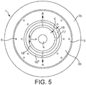
- the protruding members 6', 6" are preferably concentrically arranged and enclose the liquid inlet 4 in a continuous manner.
- annular recess 16 is preferably provided which is of width d .
- the width d preferably lies between 0.1 and 10 mm.
- the recess 16 may have a depth which corresponds to or may be less than the smallest of the respective height h ', h " of the protruding members 6', 6" enclosing the recess 16.
- the width d between the respective members may vary in case the sealing member 6 comprises a plurality of concentrically arranged protruding members 6', 6". Thereby, the width d between the respective members may in particular decrease from the centre to the peripheral portion 3b of the annular wall 3.
- the respective heights h', h" preferably differ for each of the protruding members 6', 6".
- the respective heights h' , h" preferably increase from the centre to the peripheral portion 3b of the annular wall 3.
- the respective heights h' , h" are equal for each of the protruding members 6', 6".
- each of the protruding members 18', 18" comprises at least one, preferably at least two discontinuous portions 17 of width s between the respective portions of the protruding member 18', 18".
- interstitial spaces 17 contribute to a radial outwardly orientated deflection respectively deformation of the respective portions of the protruding members 18',18" when being engaged by the convex lower surface 22a of the rotary engagement member 23 (see arrows A ).
- width d of recess 16 between the protruding members 18', 18" decreases which supports the sealing engagement.
- the recesses 16 as well as the discontinuous portion 17 may be at least partially filled with a relatively flexible or soft material.
Landscapes
- Engineering & Computer Science (AREA)
- Mechanical Engineering (AREA)
- Food Science & Technology (AREA)
- Apparatus For Making Beverages (AREA)
Claims (14)
- Kapsel (1) zum Beinhalten von Getränkeinhaltsstoffen, bestimmt zum Herstellen eines Getränks in einer Getränkezubereitungsvorrichtung (20) nach Injizieren von Flüssigkeit in die Kapsel und durch Rotieren der Kapsel um ihre Mittelachse (Z) in der Vorrichtung (20), wobei die Kapsel (1) umfasst
eine Seitenwand (2a), eine untere Wand (2b) und einen flanschartigen Rand (2c), und
eine obere Wand (3), die an den flanschartigen Rand (2c) und/oder die Seitenwand (2b) der Kapsel (1) angebracht ist,
wobei die obere Wand (3) einen zentralen Flüssigkeitseinlass (4) und periphere Auslassöffnungen (5) umfasst,
wobei die obere Wand (3) ferner ein nach außen überstehendes Dichtelement (6) umfasst, das an einem ringförmigen Abschnitt (3a) der oberen Wand (3) zwischen dem zentralen Flüssigkeitseinlass (4) und den peripheren Auslassöffnungen (5) angeordnet und so ausgelegt ist, dass es das Strömen von Flüssigkeit an der Außenseite der Kapsel (1) vom Flüssigkeitseinlass (4) zu den Auslassöffnungen (5) zumindest signifikant behindert, vorzugsweise verhindert, wenn das Dichtelement in die Getränkezubereitungsvorrichtung (20) eingesetzt ist, und
wobei das Dichtelement (6) in radialem Abstand vom Flüssigkeitseinlass (4) angeordnet ist,
dadurch gekennzeichnet, dass die Seitenwand (2a), die untere Wand (2b) und der flanschartige Rand (2c) keine Flüssigkeitseinlassöffnungen und Getränkeauslassöffnungen aufweisen. - Kapsel nach Anspruch 1,
wobei das Dichtelement (6) so angeordnet ist, dass es einen ringförmigen Raum (14) zwischen einer Außenfläche eines Injektionselements (21) der Getränkezubereitungsvorrichtung (20), wenn dieses durch den Flüssigkeitseinlass (4) eingeführt wird, und einer Innenfläche (6a) des Dichtelements (6) herstellt. - Kapsel nach einem der vorstehenden Ansprüche,
wobei das Dichtelement (6) einen Wandabschnitt bildet, der in einer im Wesentlichen parallelen Richtung zu einer Rotationsachse (Z) der Kapsel (1) aus der oberen Wand (3) übersteht. - Kapsel nach einem der vorstehenden Ansprüche,
wobei das Dichtelement (6) einen Wandabschnitt bildet, der durchgehend um den Umfang des Flüssigkeitseinlasses (4) herum angeordnet ist. - Kapsel nach einem der vorstehenden Ansprüche,
wobei das Dichtelement (6) einen röhrenförmigen Wandabschnitt (6a) mit einem Innendurchmesser (d3) umfasst, der größer ist als der Außendurchmesser (d2) des Flüssigkeitseinlasses (4). - Kapsel nach einem der Ansprüche 1 bis 3,
wobei das Dichtelement (6) mehrere Wandabschnitte bildet, die mit Unterbrechungen um den Umfang des Flüssigkeitseinlasses (4) herum angeordnet sind. - Kapsel nach Anspruch 6,
wobei das Dichtelement (6) so angeordnet ist, dass es eine labyrinthartige Wandstruktur bildet, die dazu ausgelegt ist, Flüssigkeit in Schlangenlinien vom zentralen Flüssigkeitseinlass (4) zu einem peripheren Abschnitt (3b) der oberen Wand (3) zu führen. - Kapsel nach einem der vorstehenden Ansprüche,
wobei das Dichtelement (6) dazu ausgelegt ist, nach dem Einsetzen der Kapsel (1) in eine Getränkezubereitungsvorrichtung (20) abgelenkt und/oder komprimiert zu werden. - Kapsel nach einem der vorstehenden Ansprüche,
wobei das Dichtelement (6) mindestens zwei Abschnitte (6a, 6b) umfasst, die aufeinanderfolgend in Axialrichtung verlaufen, nämlich einen Basisabschnitt (6a) bzw. einen Einsatzabschnitt (6b),
wobei der Einsatzabschnitt (6b) an einem Ende oder distalen Abschnitt des Dichtelements angeordnet ist und weicher und/oder flexibler ist als der Basisabschnitt (6a). - Kapsel nach Anspruch 9,
wobei der Einsatzabschnitt (6b) des Dichtelements aus einem Material besteht, das dazu ausgelegt ist, in Gegenwart von heißem Wasser zu erweichen, um das flüssigkeitsdichte, dichtende Eingreifen zwischen dem Flüssigkeitseinlass (4) und den Auslassöffnungen (5) zu verstärken. - Kapsel nach einem der vorstehenden Ansprüche,
wobei die obere Wand (3) in Bezug auf den flanschartigen Rand und das Dichtelement vertieft ist. - Getränkezubereitungssystem, umfassend eine Kapsel nach einem der vorstehenden Ansprüche und
Getränkezubereitungsvorrichtung (20), umfassend ein Flüssigkeitsinjektionselement (21) zum Zuführen von Flüssigkeit zur Kapsel (1) und ein umlaufendes Einsatzelement (22), dazu ausgelegt, mit dem Dichtelement (6) der Kapsel (1) zusammenzuwirken, um den Flüssigkeitseinlass (4) gegenüber den Auslassöffnungen (5) der Kapsel abzudichten. - Getränkezubereitungssystem nach Anspruch 12,
wobei das umlaufende Einsatzelement (22) konvex und/oder pyramidenförmig ausgebildet und radial außerhalb des Flüssigkeitsinjektionselements (21) angeordnet ist. - Kapselkit, umfassend:- einen rotierend symmetrischen Kapselkörper (2), der dazu bestimmt ist, von einem Verbraucher mit Getränkeinhaltsstoffen befüllt zu werden, wobei der Kapselkörper eine Seitenwand (2a), eine untere Wand (2b), eine Öffnung (9) und einen flanschartigen Rand (2c), umfasst; und- eine obere Wand oder ein Deckelelement (3), das dazu ausgelegt ist, mechanisch durch den Verbraucher mit dem Kapselkörper (2) verbunden zu werden, vorzugsweise ohne Verwendung von Werkzeugen, um die Öffnung (9) des Körpers (2) zumindest teilweise zu verschließen und im Wesentlichen das Austreten von in die Kapsel (1) gefüllten, pulverisierten oder körnigen Getränkeinhaltsstoffen zu vermeiden,wobei die obere Wand oder das Deckelelement (3) einen zentralen Flüssigkeitseinlass (4), periphere Auslassöffnungen (5) und ein nach außen überstehendes Dichtelement (6) umfasst, das an einem ringförmigen Abschnitt (3a) der oberen Wand (3) zwischen dem zentralen Flüssigkeitseinlass (4) und den peripheren Auslassöffnungen (5) angeordnet und so ausgelegt ist, dass es das Strömen von Flüssigkeit an der Außenseite der Kapsel (1) vom Flüssigkeitseinlass (4) zu den Auslassöffnungen (5) zumindest signifikant behindert, vorzugsweise verhindert, wenn das Dichtelement in die Getränkezubereitungsvorrichtung (20) eingesetzt wird, und
wobei das Dichtelement (6) in radialem Abstand vom Flüssigkeitseinlass (4) angeordnet ist,
dadurch gekennzeichnet, dass die Seitenwand (2a), die untere Wand (2b) und der flanschartige Rand (2c) keine Flüssigkeitseinlassöffnungen und keine Getränkeauslassöffnungen aufweisen.
Priority Applications (1)
| Application Number | Priority Date | Filing Date | Title |
|---|---|---|---|
| EP12783921.5A EP2776341B1 (de) | 2011-11-07 | 2012-10-26 | Kapsel zur herstellung eines getränks mit verbesserten dichtungsmitteln |
Applications Claiming Priority (3)
| Application Number | Priority Date | Filing Date | Title |
|---|---|---|---|
| EP11188104 | 2011-11-07 | ||
| PCT/EP2012/071194 WO2013068242A1 (en) | 2011-11-07 | 2012-10-26 | Capsule for preparing a beverage with enhanced sealing means |
| EP12783921.5A EP2776341B1 (de) | 2011-11-07 | 2012-10-26 | Kapsel zur herstellung eines getränks mit verbesserten dichtungsmitteln |
Publications (2)
| Publication Number | Publication Date |
|---|---|
| EP2776341A1 EP2776341A1 (de) | 2014-09-17 |
| EP2776341B1 true EP2776341B1 (de) | 2016-12-21 |
Family
ID=47148742
Family Applications (1)
| Application Number | Title | Priority Date | Filing Date |
|---|---|---|---|
| EP12783921.5A Active EP2776341B1 (de) | 2011-11-07 | 2012-10-26 | Kapsel zur herstellung eines getränks mit verbesserten dichtungsmitteln |
Country Status (3)
| Country | Link |
|---|---|
| US (1) | US9486105B2 (de) |
| EP (1) | EP2776341B1 (de) |
| WO (1) | WO2013068242A1 (de) |
Families Citing this family (22)
| Publication number | Priority date | Publication date | Assignee | Title |
|---|---|---|---|---|
| US11832755B2 (en) * | 2007-07-13 | 2023-12-05 | Adrian Rivera | Brewing material container for a beverage brewer |
| US10722066B2 (en) * | 2010-12-04 | 2020-07-28 | Adrian Rivera | Windowed single serving brewing material holder |
| US10071851B2 (en) | 2010-07-12 | 2018-09-11 | Robert Bao Vu | Apparatus and products for producing beverages, and methods for making and using same |
| KR102318476B1 (ko) * | 2010-07-22 | 2021-11-01 | 카-페 시스템 게엠베하 | 음료수 제조를 위한 1인용 캡슐 |
| MX380405B (es) | 2014-01-03 | 2025-03-12 | Douwe Egberts Bv | Paquete intercambiable de suministro para maquina de distribucion de bebida, dosificador, montaje de bomba y metodo de manufactura. |
| PT3227204T (pt) * | 2014-12-03 | 2020-03-26 | Caffitaly System Spa | Corpo de contenção para fabricar uma cápsula para preparar bebidas e método para fabricar cápsulas com diferentes quantidades de substância alimentar em pó utilizando um único tipo de corpo de contenção |
| JP6779236B2 (ja) | 2015-05-15 | 2020-11-04 | コーニンクラケ ダウ エグバート ビー.ブイ. | カプセル、そのようなカプセルから飲用可能な飲料を調製するためのシステム、およびそのようなカプセルの飲料調製装置における使用方法 |
| MX377866B (es) | 2015-05-15 | 2025-03-10 | Douwe Egberts Bv | Cápsula, sistema para preparar una bebida potable a partir de la cápsula y uso de la cápsula en un dispositivo de preparación de bebidas. |
| NL2016775B1 (en) | 2015-05-15 | 2017-01-31 | Douwe Egberts Bv | A capsule, a system for preparing a potable beverage from such a capsule and use of such a capsule in a beverage preparation device. |
| KR102633888B1 (ko) | 2015-05-15 | 2024-02-06 | 코닌클리케 도우베 에그베르츠 비.브이. | 캡슐, 이러한 캡슐로부터 마실 수 있는 음료를 제조하기 위한 시스템 및 음료 제조 장치 내의 이러한 캡슐의 이용 |
| BR122020017760B1 (pt) | 2015-05-15 | 2022-06-07 | Koninklijke Douwe Egberts B.V. | Cápsula, sistema para preparação de uma bebida potável, e, uso de uma cápsula |
| KR20180008596A (ko) | 2015-05-15 | 2018-01-24 | 코닌클리케 도우베 에그베르츠 비.브이. | 캡슐, 이러한 캡슐로부터 음용 음료를 제조하기 위한 시스템 및 음료 제조 장치 내의 이러한 캡슐의 이용 방법 |
| WO2017074189A1 (en) | 2015-10-27 | 2017-05-04 | Koninklijke Douwe Egberts B.V. | Capsule, system and method for preparing a beverage |
| NL2016779B1 (en) | 2016-05-13 | 2017-11-16 | Douwe Egberts Bv | A capsule and a system for preparing a potable beverage from such a capsule |
| NL2016780B1 (en) | 2016-05-13 | 2017-11-16 | Douwe Egberts Bv | A capsule, a system for preparing a potable beverage from such a capsule and use of such a capsule in a beverage preparation device |
| NL2017587B1 (en) | 2016-10-07 | 2018-04-16 | Douwe Egberts Bv | Capsule, system and method for preparing a beverage |
| NL2019254B9 (en) | 2016-10-07 | 2018-09-10 | Douwe Egberts Bv | A capsule, a system for preparing a potable beverage from such a capsule and use of such a capsule in a beverage preparation device |
| PL3537891T3 (pl) | 2016-11-09 | 2025-04-07 | Pepsico, Inc. | Urządzenia, sposoby i systemy do wytwarzania napojów gazowanych |
| NL2019253B1 (en) | 2017-07-14 | 2019-01-28 | Douwe Egberts Bv | Assembly of a capsule and a brew chamber, brew chamber, beverage preparation machine, capsule and use of a capsule. |
| IT201800002185A1 (it) | 2018-01-30 | 2019-07-30 | Goglio Spa | Capsula con valvola di degassazione |
| US20210107731A1 (en) * | 2018-04-11 | 2021-04-15 | Goglio S.P.A. | Capsules for preparing beverages, particularly coffees |
| US11805934B1 (en) * | 2020-10-21 | 2023-11-07 | Adrian Rivera | Brewing material lid and container for a beverage brewer |
Citations (1)
| Publication number | Priority date | Publication date | Assignee | Title |
|---|---|---|---|---|
| EP1704803A1 (de) * | 2005-03-22 | 2006-09-27 | Tuttoespresso S.p.a. | Kartusche für Getränke und System |
Family Cites Families (11)
| Publication number | Priority date | Publication date | Assignee | Title |
|---|---|---|---|---|
| DE10211327B4 (de) * | 2002-03-14 | 2015-09-24 | Caffitaly System S.P.A. | Portionenkapsel mit einer partikelförmigen mittels Wasser extrahierbaren Substanz zur Herstellung eines Getränks |
| CA2687894C (en) | 2007-06-05 | 2016-05-10 | Nestec S.A. | Capsule system, device and method for preparing a food liquid contained in a receptacle by centrifugation |
| CN101959446B (zh) * | 2008-02-29 | 2014-04-16 | 雀巢产品技术援助有限公司 | 利用离心力由容器制备液体提取物的方法和系统 |
| US20090229470A1 (en) * | 2008-03-12 | 2009-09-17 | My-Kap, Llc | Coffee Cartridge Lid Apparatus and Method |
| RU2508895C2 (ru) * | 2008-12-03 | 2014-03-10 | Нестек С.А. | Капсула для приготовления напитка методом центрифугирования |
| ES2382717T3 (es) * | 2009-03-31 | 2012-06-12 | Nestec S.A. | Cápsula con filtro para preparar una composición nutritiva o alimenticia, líquida, y sistema de producción de una bebida correspondientemente en concordancia |
| EP2239212B1 (de) * | 2009-04-09 | 2015-11-11 | Nestec S.A. | Kapsel zur Herstellung eines Getränks mit einer einen Strömungspfad aufweisenden Ausgabewand |
| ITBO20090039U1 (it) | 2009-05-20 | 2010-11-21 | Torrefazione Mokador S R L | Capsula per prodotti da infusione. |
| JP6174858B2 (ja) * | 2009-06-17 | 2017-08-02 | コーニンクラケ ダウ エグバート ビー.ブイ. | 摂取に適する所定量の飲料を用意するためのカプセル、システム及び方法 |
| DE202009014945U1 (de) * | 2009-08-05 | 2010-09-23 | Nestec S.A. | Kapsel mit reliefförmigen Dichtungselement |
| US8783492B2 (en) * | 2010-10-14 | 2014-07-22 | Eric Petitpas | Cover for single serving beverage filter container |
-
2012
- 2012-10-26 WO PCT/EP2012/071194 patent/WO2013068242A1/en not_active Ceased
- 2012-10-26 EP EP12783921.5A patent/EP2776341B1/de active Active
- 2012-10-26 US US14/356,774 patent/US9486105B2/en active Active
Patent Citations (1)
| Publication number | Priority date | Publication date | Assignee | Title |
|---|---|---|---|---|
| EP1704803A1 (de) * | 2005-03-22 | 2006-09-27 | Tuttoespresso S.p.a. | Kartusche für Getränke und System |
Also Published As
| Publication number | Publication date |
|---|---|
| US20140314919A1 (en) | 2014-10-23 |
| US9486105B2 (en) | 2016-11-08 |
| EP2776341A1 (de) | 2014-09-17 |
| WO2013068242A1 (en) | 2013-05-16 |
Similar Documents
| Publication | Publication Date | Title |
|---|---|---|
| EP2776341B1 (de) | Kapsel zur herstellung eines getränks mit verbesserten dichtungsmitteln | |
| EP2771260B1 (de) | Kapsel zur herstellung eines getränks durch zentrifugierung mit einem dichtflansch | |
| US10144579B2 (en) | Capsule with reinforcement members used for the preparation of a beverage | |
| JP6100886B2 (ja) | 遠心浸出装置内の飲料調製用カプセル | |
| EP3110722B1 (de) | Kapsel für getränke | |
| KR101914802B1 (ko) | 음료 생산 장치에서 음료를 제조하기 위한 캡슐 | |
| US20140087028A1 (en) | Portioned package for espresso machines | |
| AU2014201947B2 (en) | Capsule for preparing a beverage | |
| EP2771258B1 (de) | Modularer kapselsatz mit variablem volumen |
Legal Events
| Date | Code | Title | Description |
|---|---|---|---|
| PUAI | Public reference made under article 153(3) epc to a published international application that has entered the european phase |
Free format text: ORIGINAL CODE: 0009012 |
|
| 17P | Request for examination filed |
Effective date: 20140610 |
|
| AK | Designated contracting states |
Kind code of ref document: A1 Designated state(s): AL AT BE BG CH CY CZ DE DK EE ES FI FR GB GR HR HU IE IS IT LI LT LU LV MC MK MT NL NO PL PT RO RS SE SI SK SM TR |
|
| DAX | Request for extension of the european patent (deleted) | ||
| 17Q | First examination report despatched |
Effective date: 20150826 |
|
| GRAP | Despatch of communication of intention to grant a patent |
Free format text: ORIGINAL CODE: EPIDOSNIGR1 |
|
| INTG | Intention to grant announced |
Effective date: 20160930 |
|
| GRAS | Grant fee paid |
Free format text: ORIGINAL CODE: EPIDOSNIGR3 |
|
| GRAA | (expected) grant |
Free format text: ORIGINAL CODE: 0009210 |
|
| STAA | Information on the status of an ep patent application or granted ep patent |
Free format text: STATUS: THE PATENT HAS BEEN GRANTED |
|
| AK | Designated contracting states |
Kind code of ref document: B1 Designated state(s): AL AT BE BG CH CY CZ DE DK EE ES FI FR GB GR HR HU IE IS IT LI LT LU LV MC MK MT NL NO PL PT RO RS SE SI SK SM TR |
|
| REG | Reference to a national code |
Ref country code: GB Ref legal event code: FG4D |
|
| REG | Reference to a national code |
Ref country code: CH Ref legal event code: EP |
|
| REG | Reference to a national code |
Ref country code: IE Ref legal event code: FG4D |
|
| REG | Reference to a national code |
Ref country code: AT Ref legal event code: REF Ref document number: 855252 Country of ref document: AT Kind code of ref document: T Effective date: 20170115 |
|
| REG | Reference to a national code |
Ref country code: DE Ref legal event code: R096 Ref document number: 602012026892 Country of ref document: DE |
|
| PG25 | Lapsed in a contracting state [announced via postgrant information from national office to epo] |
Ref country code: LV Free format text: LAPSE BECAUSE OF FAILURE TO SUBMIT A TRANSLATION OF THE DESCRIPTION OR TO PAY THE FEE WITHIN THE PRESCRIBED TIME-LIMIT Effective date: 20161221 |
|
| REG | Reference to a national code |
Ref country code: NL Ref legal event code: FP |
|
| REG | Reference to a national code |
Ref country code: LT Ref legal event code: MG4D |
|
| PG25 | Lapsed in a contracting state [announced via postgrant information from national office to epo] |
Ref country code: GR Free format text: LAPSE BECAUSE OF FAILURE TO SUBMIT A TRANSLATION OF THE DESCRIPTION OR TO PAY THE FEE WITHIN THE PRESCRIBED TIME-LIMIT Effective date: 20170322 Ref country code: LT Free format text: LAPSE BECAUSE OF FAILURE TO SUBMIT A TRANSLATION OF THE DESCRIPTION OR TO PAY THE FEE WITHIN THE PRESCRIBED TIME-LIMIT Effective date: 20161221 Ref country code: NO Free format text: LAPSE BECAUSE OF FAILURE TO SUBMIT A TRANSLATION OF THE DESCRIPTION OR TO PAY THE FEE WITHIN THE PRESCRIBED TIME-LIMIT Effective date: 20170321 Ref country code: SE Free format text: LAPSE BECAUSE OF FAILURE TO SUBMIT A TRANSLATION OF THE DESCRIPTION OR TO PAY THE FEE WITHIN THE PRESCRIBED TIME-LIMIT Effective date: 20161221 |
|
| REG | Reference to a national code |
Ref country code: AT Ref legal event code: MK05 Ref document number: 855252 Country of ref document: AT Kind code of ref document: T Effective date: 20161221 |
|
| PG25 | Lapsed in a contracting state [announced via postgrant information from national office to epo] |
Ref country code: FI Free format text: LAPSE BECAUSE OF FAILURE TO SUBMIT A TRANSLATION OF THE DESCRIPTION OR TO PAY THE FEE WITHIN THE PRESCRIBED TIME-LIMIT Effective date: 20161221 Ref country code: RS Free format text: LAPSE BECAUSE OF FAILURE TO SUBMIT A TRANSLATION OF THE DESCRIPTION OR TO PAY THE FEE WITHIN THE PRESCRIBED TIME-LIMIT Effective date: 20161221 Ref country code: HR Free format text: LAPSE BECAUSE OF FAILURE TO SUBMIT A TRANSLATION OF THE DESCRIPTION OR TO PAY THE FEE WITHIN THE PRESCRIBED TIME-LIMIT Effective date: 20161221 |
|
| PG25 | Lapsed in a contracting state [announced via postgrant information from national office to epo] |
Ref country code: IS Free format text: LAPSE BECAUSE OF FAILURE TO SUBMIT A TRANSLATION OF THE DESCRIPTION OR TO PAY THE FEE WITHIN THE PRESCRIBED TIME-LIMIT Effective date: 20170421 Ref country code: CZ Free format text: LAPSE BECAUSE OF FAILURE TO SUBMIT A TRANSLATION OF THE DESCRIPTION OR TO PAY THE FEE WITHIN THE PRESCRIBED TIME-LIMIT Effective date: 20161221 Ref country code: EE Free format text: LAPSE BECAUSE OF FAILURE TO SUBMIT A TRANSLATION OF THE DESCRIPTION OR TO PAY THE FEE WITHIN THE PRESCRIBED TIME-LIMIT Effective date: 20161221 Ref country code: RO Free format text: LAPSE BECAUSE OF FAILURE TO SUBMIT A TRANSLATION OF THE DESCRIPTION OR TO PAY THE FEE WITHIN THE PRESCRIBED TIME-LIMIT Effective date: 20161221 Ref country code: SK Free format text: LAPSE BECAUSE OF FAILURE TO SUBMIT A TRANSLATION OF THE DESCRIPTION OR TO PAY THE FEE WITHIN THE PRESCRIBED TIME-LIMIT Effective date: 20161221 |
|
| PG25 | Lapsed in a contracting state [announced via postgrant information from national office to epo] |
Ref country code: PL Free format text: LAPSE BECAUSE OF FAILURE TO SUBMIT A TRANSLATION OF THE DESCRIPTION OR TO PAY THE FEE WITHIN THE PRESCRIBED TIME-LIMIT Effective date: 20161221 Ref country code: ES Free format text: LAPSE BECAUSE OF FAILURE TO SUBMIT A TRANSLATION OF THE DESCRIPTION OR TO PAY THE FEE WITHIN THE PRESCRIBED TIME-LIMIT Effective date: 20161221 Ref country code: BE Free format text: LAPSE BECAUSE OF FAILURE TO SUBMIT A TRANSLATION OF THE DESCRIPTION OR TO PAY THE FEE WITHIN THE PRESCRIBED TIME-LIMIT Effective date: 20161221 Ref country code: PT Free format text: LAPSE BECAUSE OF FAILURE TO SUBMIT A TRANSLATION OF THE DESCRIPTION OR TO PAY THE FEE WITHIN THE PRESCRIBED TIME-LIMIT Effective date: 20170421 Ref country code: SM Free format text: LAPSE BECAUSE OF FAILURE TO SUBMIT A TRANSLATION OF THE DESCRIPTION OR TO PAY THE FEE WITHIN THE PRESCRIBED TIME-LIMIT Effective date: 20161221 Ref country code: BG Free format text: LAPSE BECAUSE OF FAILURE TO SUBMIT A TRANSLATION OF THE DESCRIPTION OR TO PAY THE FEE WITHIN THE PRESCRIBED TIME-LIMIT Effective date: 20170321 Ref country code: AT Free format text: LAPSE BECAUSE OF FAILURE TO SUBMIT A TRANSLATION OF THE DESCRIPTION OR TO PAY THE FEE WITHIN THE PRESCRIBED TIME-LIMIT Effective date: 20161221 |
|
| REG | Reference to a national code |
Ref country code: FR Ref legal event code: PLFP Year of fee payment: 6 |
|
| REG | Reference to a national code |
Ref country code: DE Ref legal event code: R097 Ref document number: 602012026892 Country of ref document: DE |
|
| PLBE | No opposition filed within time limit |
Free format text: ORIGINAL CODE: 0009261 |
|
| STAA | Information on the status of an ep patent application or granted ep patent |
Free format text: STATUS: NO OPPOSITION FILED WITHIN TIME LIMIT |
|
| 26N | No opposition filed |
Effective date: 20170922 |
|
| PG25 | Lapsed in a contracting state [announced via postgrant information from national office to epo] |
Ref country code: DK Free format text: LAPSE BECAUSE OF FAILURE TO SUBMIT A TRANSLATION OF THE DESCRIPTION OR TO PAY THE FEE WITHIN THE PRESCRIBED TIME-LIMIT Effective date: 20161221 |
|
| PG25 | Lapsed in a contracting state [announced via postgrant information from national office to epo] |
Ref country code: SI Free format text: LAPSE BECAUSE OF FAILURE TO SUBMIT A TRANSLATION OF THE DESCRIPTION OR TO PAY THE FEE WITHIN THE PRESCRIBED TIME-LIMIT Effective date: 20161221 |
|
| PG25 | Lapsed in a contracting state [announced via postgrant information from national office to epo] |
Ref country code: MC Free format text: LAPSE BECAUSE OF FAILURE TO SUBMIT A TRANSLATION OF THE DESCRIPTION OR TO PAY THE FEE WITHIN THE PRESCRIBED TIME-LIMIT Effective date: 20161221 |
|
| REG | Reference to a national code |
Ref country code: NL Ref legal event code: MM Effective date: 20171101 |
|
| GBPC | Gb: european patent ceased through non-payment of renewal fee |
Effective date: 20171026 |
|
| REG | Reference to a national code |
Ref country code: IE Ref legal event code: MM4A |
|
| PG25 | Lapsed in a contracting state [announced via postgrant information from national office to epo] |
Ref country code: NL Free format text: LAPSE BECAUSE OF NON-PAYMENT OF DUE FEES Effective date: 20171101 Ref country code: GB Free format text: LAPSE BECAUSE OF NON-PAYMENT OF DUE FEES Effective date: 20171026 Ref country code: LU Free format text: LAPSE BECAUSE OF NON-PAYMENT OF DUE FEES Effective date: 20171026 |
|
| REG | Reference to a national code |
Ref country code: FR Ref legal event code: PLFP Year of fee payment: 7 |
|
| PG25 | Lapsed in a contracting state [announced via postgrant information from national office to epo] |
Ref country code: MT Free format text: LAPSE BECAUSE OF NON-PAYMENT OF DUE FEES Effective date: 20171026 |
|
| PG25 | Lapsed in a contracting state [announced via postgrant information from national office to epo] |
Ref country code: IT Free format text: LAPSE BECAUSE OF NON-PAYMENT OF DUE FEES Effective date: 20171026 Ref country code: IE Free format text: LAPSE BECAUSE OF NON-PAYMENT OF DUE FEES Effective date: 20171026 |
|
| PG25 | Lapsed in a contracting state [announced via postgrant information from national office to epo] |
Ref country code: HU Free format text: LAPSE BECAUSE OF FAILURE TO SUBMIT A TRANSLATION OF THE DESCRIPTION OR TO PAY THE FEE WITHIN THE PRESCRIBED TIME-LIMIT; INVALID AB INITIO Effective date: 20121026 |
|
| REG | Reference to a national code |
Ref country code: CH Ref legal event code: PFUS Owner name: SOCIETE DES PRODUITS NESTLE S.A., CH Free format text: FORMER OWNER: NESTEC S.A., CH |
|
| PG25 | Lapsed in a contracting state [announced via postgrant information from national office to epo] |
Ref country code: CY Free format text: LAPSE BECAUSE OF NON-PAYMENT OF DUE FEES Effective date: 20161221 |
|
| PG25 | Lapsed in a contracting state [announced via postgrant information from national office to epo] |
Ref country code: MK Free format text: LAPSE BECAUSE OF FAILURE TO SUBMIT A TRANSLATION OF THE DESCRIPTION OR TO PAY THE FEE WITHIN THE PRESCRIBED TIME-LIMIT Effective date: 20161221 |
|
| REG | Reference to a national code |
Ref country code: DE Ref legal event code: R082 Ref document number: 602012026892 Country of ref document: DE Representative=s name: MITSCHERLICH, PATENT- UND RECHTSANWAELTE PARTM, DE Ref country code: DE Ref legal event code: R081 Ref document number: 602012026892 Country of ref document: DE Owner name: SOCIETE DES PRODUITS NESTLE S.A., CH Free format text: FORMER OWNER: NESTEC S.A., VEVEY, CH |
|
| PG25 | Lapsed in a contracting state [announced via postgrant information from national office to epo] |
Ref country code: TR Free format text: LAPSE BECAUSE OF FAILURE TO SUBMIT A TRANSLATION OF THE DESCRIPTION OR TO PAY THE FEE WITHIN THE PRESCRIBED TIME-LIMIT Effective date: 20161221 |
|
| PG25 | Lapsed in a contracting state [announced via postgrant information from national office to epo] |
Ref country code: AL Free format text: LAPSE BECAUSE OF FAILURE TO SUBMIT A TRANSLATION OF THE DESCRIPTION OR TO PAY THE FEE WITHIN THE PRESCRIBED TIME-LIMIT Effective date: 20161221 |
|
| P01 | Opt-out of the competence of the unified patent court (upc) registered |
Effective date: 20230527 |
|
| PGFP | Annual fee paid to national office [announced via postgrant information from national office to epo] |
Ref country code: FR Payment date: 20250908 Year of fee payment: 14 |
|
| REG | Reference to a national code |
Ref country code: CH Ref legal event code: U11 Free format text: ST27 STATUS EVENT CODE: U-0-0-U10-U11 (AS PROVIDED BY THE NATIONAL OFFICE) Effective date: 20251101 |
|
| PGFP | Annual fee paid to national office [announced via postgrant information from national office to epo] |
Ref country code: DE Payment date: 20250902 Year of fee payment: 14 |
|
| PGFP | Annual fee paid to national office [announced via postgrant information from national office to epo] |
Ref country code: CH Payment date: 20251101 Year of fee payment: 14 |