EP2776593B1 - Appareil et procédé pour positionner des lances de four électrique à arc, four électrique à arc comprenant un tel appareil - Google Patents
Appareil et procédé pour positionner des lances de four électrique à arc, four électrique à arc comprenant un tel appareil Download PDFInfo
- Publication number
- EP2776593B1 EP2776593B1 EP12790640.2A EP12790640A EP2776593B1 EP 2776593 B1 EP2776593 B1 EP 2776593B1 EP 12790640 A EP12790640 A EP 12790640A EP 2776593 B1 EP2776593 B1 EP 2776593B1
- Authority
- EP
- European Patent Office
- Prior art keywords
- lance
- furnace
- electric arc
- arc furnace
- steelmaking
- Prior art date
- Legal status (The legal status is an assumption and is not a legal conclusion. Google has not performed a legal analysis and makes no representation as to the accuracy of the status listed.)
- Active
Links
Images




Classifications
-
- F—MECHANICAL ENGINEERING; LIGHTING; HEATING; WEAPONS; BLASTING
- F27—FURNACES; KILNS; OVENS; RETORTS
- F27B—FURNACES, KILNS, OVENS OR RETORTS IN GENERAL; OPEN SINTERING OR LIKE APPARATUS
- F27B3/00—Hearth-type furnaces, e.g. of reverberatory type; Electric arc furnaces ; Tank furnaces
- F27B3/10—Details, accessories or equipment, e.g. dust-collectors, specially adapted for hearth-type furnaces
- F27B3/22—Arrangements of air or gas supply devices
-
- C—CHEMISTRY; METALLURGY
- C21—METALLURGY OF IRON
- C21C—PROCESSING OF PIG-IRON, e.g. REFINING, MANUFACTURE OF WROUGHT-IRON OR STEEL; TREATMENT IN MOLTEN STATE OF FERROUS ALLOYS
- C21C5/00—Manufacture of carbon-steel, e.g. plain mild steel, medium carbon steel or cast steel or stainless steel
- C21C5/52—Manufacture of steel in electric furnaces
-
- C—CHEMISTRY; METALLURGY
- C21—METALLURGY OF IRON
- C21C—PROCESSING OF PIG-IRON, e.g. REFINING, MANUFACTURE OF WROUGHT-IRON OR STEEL; TREATMENT IN MOLTEN STATE OF FERROUS ALLOYS
- C21C5/00—Manufacture of carbon-steel, e.g. plain mild steel, medium carbon steel or cast steel or stainless steel
- C21C5/52—Manufacture of steel in electric furnaces
- C21C5/5211—Manufacture of steel in electric furnaces in an alternating current [AC] electric arc furnace
- C21C5/5217—Manufacture of steel in electric furnaces in an alternating current [AC] electric arc furnace equipped with burners or devices for injecting gas, i.e. oxygen, or pulverulent materials into the furnace
-
- F—MECHANICAL ENGINEERING; LIGHTING; HEATING; WEAPONS; BLASTING
- F27—FURNACES; KILNS; OVENS; RETORTS
- F27B—FURNACES, KILNS, OVENS OR RETORTS IN GENERAL; OPEN SINTERING OR LIKE APPARATUS
- F27B3/00—Hearth-type furnaces, e.g. of reverberatory type; Electric arc furnaces ; Tank furnaces
- F27B3/08—Hearth-type furnaces, e.g. of reverberatory type; Electric arc furnaces ; Tank furnaces heated electrically, with or without any other source of heat
- F27B3/085—Arc furnaces
-
- F—MECHANICAL ENGINEERING; LIGHTING; HEATING; WEAPONS; BLASTING
- F27—FURNACES; KILNS; OVENS; RETORTS
- F27B—FURNACES, KILNS, OVENS OR RETORTS IN GENERAL; OPEN SINTERING OR LIKE APPARATUS
- F27B3/00—Hearth-type furnaces, e.g. of reverberatory type; Electric arc furnaces ; Tank furnaces
- F27B3/10—Details, accessories or equipment, e.g. dust-collectors, specially adapted for hearth-type furnaces
- F27B3/22—Arrangements of air or gas supply devices
- F27B3/225—Oxygen blowing
-
- Y—GENERAL TAGGING OF NEW TECHNOLOGICAL DEVELOPMENTS; GENERAL TAGGING OF CROSS-SECTIONAL TECHNOLOGIES SPANNING OVER SEVERAL SECTIONS OF THE IPC; TECHNICAL SUBJECTS COVERED BY FORMER USPC CROSS-REFERENCE ART COLLECTIONS [XRACs] AND DIGESTS
- Y02—TECHNOLOGIES OR APPLICATIONS FOR MITIGATION OR ADAPTATION AGAINST CLIMATE CHANGE
- Y02P—CLIMATE CHANGE MITIGATION TECHNOLOGIES IN THE PRODUCTION OR PROCESSING OF GOODS
- Y02P10/00—Technologies related to metal processing
- Y02P10/20—Recycling
Definitions
- the present invention relates to the metallurgy field, particularly to steelmaking by means of systems provided with electric arc furnaces (EAFs).
- EAFs electric arc furnaces
- a particular type of furnace, to which the present invention is advantageously applied, is that of tilting EAFs: these furnaces, in operation, follow an oscillation driven about a horizontal axis, being tilted by about 15°.
- Such injection is usually made by the so-called “lances” that thus are able to integrate the electric energy produced by electric arcs of electrodes adding chemical energy to the system, to introduce free oxygen in the furnace for converting CO (a by-product of steelmaking reactions) into CO2 (to produce additional heat), to inject elements for causing the slag to foam in order to improve the stability of the electric arc and in order to keep it covered improving the heat transfer to the steel bath and to reduce heat losses towards the shell and the roof of the furnace, to inject elements in the molten metal for accelerating steel refining, to contribute in making the bath homogeneous by enhancing the stirring, etc.
- Lances that thus are able to integrate the electric energy produced by electric arcs of electrodes adding chemical energy to the system, to introduce free oxygen in the furnace for converting CO (a by-product of steelmaking reactions) into CO2 (to produce additional heat), to inject elements for causing the slag to foam in order to improve the stability of the electric arc and in order to keep it covered improving the heat transfer
- All these actions can be performed by a plurality of lance types (that is consumable, movable, fixed, internal, external the furnace, etc.), all closely connected to the supporting structure that, ultimately, can be considered one of the most important means that allow lances to efficaciously perform their task.
- the historical "slag door lance" was, by far, the most widespread type of lance.
- the relevant supporting structure had to allow the lance to reach a suitable point of the bath through a door that should have been used also for controlling the slag level in the de-slagging phase.
- internal lances means that the lances are fitted on the furnace support represented by the shell of the EAF or also by the side wall.
- this "closeness" to the bath involves reagents (for example oxygen) to be injected near the refractory lining. This, in turn, could increase the erosion of the refractory lining and reduce the service life of the furnace.
- reagents for example oxygen
- the assembly position of the lance which has to be fixed, can be optimized for the injection of elements while the stirring effect remains localized in a small area of the steel bath near the injection point.
- the tower supported thereon has an overall dimension external to the furnace that is too much remarkable for many applications and, moreover, the means for adjusting the position have to be provided completely coordinated by the electronics; this finally leads to the fact of having a more complicated and, therefore, less reliable control system,.
- the document JP 2001-335825 to SINTOKOGIO Ltd describes a device for injecting oxygen and powdery material into the molten metal in the arc type electric furnace for steelmaking, which is still constituted of a carriage (the trolley in BEDA patent) which is formed so as to be freely moved at the front of the furnace; as it is clearly shown in fig.2 in the present application, the swing is obtained by said device by means of a joint that has its axis of rotation on the carriage - this similarly occurs substantially also for the longitudinal axis of the tower in BEDA patent.
- the position of the lance tip (where the spreading nozzle is mounted) can follow only one specific path, therefore a great part of the bath cannot be reached and other areas can be reached with angled injection properties that are not optimized.
- a further need is required for a lance apparatus to be suitably adapted to a EAF equipped with the Consteel® system - the same Applicant being the owner - using a conveyor for continuously feeding slag to the EAF, unlike a conventional top charge EAF of the single charge type.
- the aim of the present invention is to overcome the prior art drawbacks.
- the main object of the present invention is therefore to provide a positioning apparatus for steelmaking lances of an electric arc furnace arranged for minimizing the dimension required for the opening of the side wall through which said lances have access to the liquid bath.
- a second object of the present invention is further to provide a positioning apparatus for steelmaking lance of an electric arc furnace wherein the minimized dimension of said opening of the side wall does not limit the ranges of the positioning angles permitted to the lance.
- Another object of the present invention is to provide a positioning apparatus for steelmaking lances of an electric arc furnace mechanically automatized for positioning the tip of the lance into the liquid bath, thus not requiring a complex control of the positioning apparatus.
- a further object of the present invention is to provide a positioning apparatus for steelmaking lances of an electric arc furnace arranged with respect to the EAF to which they are applied in such a way as to be tiltable therewith.
- a further object of the present invention is to provide a positioning apparatus for steelmaking lances of an electric arc furnace allowing an easy maintenance of the EAF which typically consists in removing and replacing the furnace that is typically made of two parts that are the upper shell of the EAF (generally composed of water cooled panels) and of the vessel of the EAF (or refractory lining of the lower shell).
- a further object of the present invention is to provide a method for positioning a steelmaking lance in an electric arc furnace from a first position outside the shell of said electric arc furnace to a second position in said shell, said method minimizing the manoeuvres of the lances and the space required for performing said manoeuvres.
- Still another object of the present invention is to provide a steelmaking system comprising a EAF of the tilting type and a positioning apparatus for a lance that minimizes the space required for moving the latter, easy to be made and that can use conventional straight lances.
- the idea at the base of the present invention is to make a positioning apparatus for straight steelmaking lances in an electric arc furnace of the tilting type, wherein the apparatus comprises a supporting structure for the lance associated to the furnace such to be tiltable with the latter in order to maintain an optimal injection angle regardless of the tilting.
- the positioning apparatus advantageously comprises a linkage associated to the supporting structure and intended to position a carriage that slides with respect to the linkage itself.
- the linkage is an articulated quadrilateral intended to cause the lance to be moved from a position outside said furnace to an operating position wherein at least the front part of the lance is inside the furnace;
- the positioning apparatus comprises rotation means to cause at least the carriage to rotate about a substantially vertical axis with the lance in the operating (or assembly) condition.
- substantially vertical means an arrangement of said axis that is substantially parallel to the vector of the force of gravity with a possible tolerance of some degrees, preferably ⁇ 5°.
- the positioning apparatus 100,100',100" for steelmaking lances 300 of a tilting electric arc furnace 200 is coupled to the furnace 200 such to be tiltable therewith.
- the apparatus 100,100',100" comprises a supporting structure 150,150' for the lance 300 intended to be introduced in the furnace 200 through an opening 230 in its shell wall; the apparatus further comprises a linkage 110, 120, 130, 160 associated to the supporting structure 150,150' and intended to position a sliding carriage 115 upon which the lance 300 is fitted, preferably in a fixed manner.
- the linkage 110, 120, 130, 160 is an articulated quadrilateral by means of which the lance 300 is moved from a first parking position, wherein the whole lance is outside (or external to) the volume of the furnace, to a second operating position, wherein at least the front portion of the lance is inside the volume of the electric arc furnace.
- the positioning apparatus 100,100',100" comprises rotation means for causing the carriage 115 to rotate about an axis X arranged substantially vertical in the assembly condition.
- the axis X that is to say, is the centre of rotation about which the carriage 115 supporting the lance 300 rotates.
- the positioning of the axis X has a considerable importance as regards the two opposing purposes of compactness of the arrangement and the area covered by the lance tip in the bath during the rotation of the carriage 115.
- the axis X with the lance in the operating condition (that is in the above mentioned second position), intercepts the straight line on which the rod 110 of the articulated quadrilateral develops at a distance (measured from the rod end closest to the furnace and in a direction perpendicular to the axis X - that is horizontally) not exceeding the thickness of the furnace wall.
- the axis X passes through or lies in a position close to the opening 230; with reference thereto it has to be noted that the term "opening" 230 means the port of the shell wall of the furnace through which the lance passes.
- Such opening is therefore defined by the edges of the port, comprising also those defined by the cooling tube bundle delimiting it.
- the axis X it has to be noted that, in the system comprising also the EAF, it is arranged such to intercept the furnace or it is arranged outside it at a distance approximately equal to that of the wall made of refractory material of the furnace.
- a tilting electric arc furnace EAF 200 is shown with a set of three vertical electrodes 210 placed symmetrically with respect to the centre of a circular path 215.
- Fig. 1 shows also a positioning apparatus 100 according to a preferred embodiment of the present invention supporting a steelmaking lance 300 arranged in its operating position, that is inserted through an opening 230 of the top shell 220 of the EAF in the EAF 200.
- the opening 230 to which reference is made is the port visible from the inside of the furnace and it does not exactly coincide with the shell wall area where the refractory material is not provided: such port on the contrary is defined by its edges delimited by the tube bundle of the cooling system.
- the lance 300 is of the straight type, that is provided with a body containing inner ducts following a linear development inside it; such lances 300 generally are of the "standard" type that is ordinary in the sector of the art, therefore they are not further described.
- the corresponding swinging movement occurs by rotating the whole positioning apparatus 100 about a vertical axis X passing by the opening 230 of the upper shell 220 of the EAF.
- the swing angle between directions E1 and E2 is about 60 degrees.
- the positioning apparatus 100 comprises a partially rotating supporting structure 150 and an articulated quadrilateral supported thereon.
- the structure 150 is articulated, meaning that it comprises a first portion 150A integral with the furnace 200 secured to the lower outer part of the lower shell 260 of the EAF and a second portion 150B rotatable with respect to the first one by means of a hinge 155 connecting them together.
- the axis of said hinge is the axis of rotation X described above.
- a plate 160 preferably radially arranged with respect to said axis X.
- the plate 160 is the frame of the articulated quadrilateral.
- rocker arms 120, 130 It comprises, in addition to the frame 160, two rocker arms 120, 130: a first end 121 of a first rocker arm 120 and a first end 131 of a second rocker arm 130 are hinged to the frame 160, the end 131 being farther from the axis X than the end 121.
- the second ends 122 and 132 of said rocker arms 120 and 130, respectively, are in turn each one hinged to a rod 110 of the articulated quadrilateral, that in this embodiment is shaped as a rail such to allow the relative sliding of a carriage 115 thereon.
- said steelmaking lance 300 is fastened on said carriage 115 and is movable thereon.
- the positioning apparatus 100 described, and consequently, the lance 300 have three degrees of freedom:
- Each one of the three degrees of freedom is controlled by driving means properly adapted to each joint or hinge: a first double-acting hydraulic cylinder (not shown) drives in a controllable manner the rotation of the first and second portions 150A and 150B about the hinge 155, a double-acting hydraulic cylinder 140 has its head 145 connected to the first arm 120 near its first end 121, while a telescopic hydraulic cylinder 16 drives the carriage 115 in its sliding arrangement.
- a first double-acting hydraulic cylinder (not shown) drives in a controllable manner the rotation of the first and second portions 150A and 150B about the hinge 155
- a double-acting hydraulic cylinder 140 has its head 145 connected to the first arm 120 near its first end 121
- a telescopic hydraulic cylinder 16 drives the carriage 115 in its sliding arrangement.
- the articulated quadrilateral composed in this manner can be designed so as to reach the uppermost position of the steelmaking lance 300 optimized on the basis of different parameters such as the dimension required for the opening 230, as already seen, the configuration adopted for the electrodes - or the shape and depth of the lower shell 240 of the EAF and of the upper shell 220.
- said upper optimized position is reached by an angle of rotation ranging from 40 degrees to 45 degrees: the previous range results from a balance between the minimum distance at which the lance tip has to be carried from the liquid steel bath 280 through the layer 285 of foamed slag and a kind of safety distance of the tip from the refractory lining 290.
- the fact of blowing oxygen near said lining leads it to be rapidly worn out.
- each arm 120 and 130, of the frame 160 and of the rail 110 can be suitably selected for minimizing the overall dimension of the positioning apparatus 100 depending on the space available in the plant around the furnace.
- the arm 120 of the preferred embodiment shown in the figures has an arcuate profile both in order to guarantee the necessary distance between the end 121 and the end 122 for the desired rotation and height of the rail 115 and in order to avoid the positioning apparatus 100 and the shell 200 from colliding.
- the length of the rail 110 and therefore the travel of the carriage 115, can be designed such to allow the lance tip to reach the free surface of the liquid bath at any level thereof, maintaining an optimized path of the rail 110 during the rotation of the arm 120 from the parking position to the operating position: such path depends on the distance between the hinged ends 122 and 132.
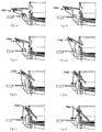
- Figs. 4f to 4h show the sliding movement of the carriage 115 along the rail 110 once it is arranged in its operating position: the carriage 115 is advanced till the tip of the steelmaking lance 300 - comprising a oxygen lance 310 and a lance 320 for supplying material containing carbon laying thereon - reaches a safety distance from the free surface of the steel bath 280.
- the level of the steel bath increases as the process goes on and therefore the tip of steelmaking lances 300 has to be raised in agreement with the current level.
- the tip of the lances 310 and 320 has to follow such displacement.
- FIG. 1 a cross-section view of the opening 230 of the side wall which is adjusted to the space taken by the steelmaking lances 300 once they are in the operating position, thus minimizing not only the heat losses but also the input of atmospheric air and, at the same time, leaving to the lances 310 and 320 the freedom to slide in and out therefrom and to rotate about the axis X such to cover all the injection area selected such to achieve the targets of the steelmaking process.
- the hinge 155 is placed with respect to the side wall 210 of the EAF 200 in such a way that the axis X, about which the hinge 150 rotates, is flush with the innermost part of the opening 230 of the side wall: according to such configuration of the hinge 150 the steelmaking lances 300 require a horizontal dimension as small as possible for the opening 230 that therefore allows minimum heat losses.
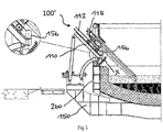
- a first alternative embodiment of the invention is shown in fig.5 .
- the positioning apparatus 100' uses, instead of the articulated structure 150 with the hinge 155, a structure fixed with the furnace 150'.
- rotation means comprise the hinge 156 of fig. 5 that articulates the rotating arm 112 on which the carriage 115 is arranged which is associated to the lance 300.
- the axis of rotation X therefore coincides with the axis of the hinge 156: it has to be noted that in this solution it is arranged past the outer face of the furnace, towards its inside. This also guarantees the making of a smaller port, even if in case of a malfunction with the lance stopped in the angled position, there are some difficulties in taking it out.
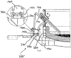
- a second variant is shown in figs. 6 and 7 : in this variant the axis X coincides with the centre of the trajectory of two rails 270 that develop on a circumference arc path and that can be run across by a movement carriage 157 that integrally bears the frame 160 of the articulated quadrilateral, such to guarantee the movement of the lance as a function of the movement of the whole articulated quadrilateral.
- FIG. 1 Another embodiment of the positioning apparatus 100 has a telescopic arm 130 (not shown) as the second rocker arm that therefore replaces the second hinged arm 130 described for the preferred embodiment.
- This solution can be particularly useful in the case a further reduction of the radial space is desired.
- said telescopic arm 130 can be hydraulically driven as the driving tool instead of the hydraulic cylinder 140.
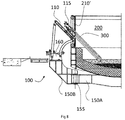
- fig. 8 shows a last variant, wherein an apparatus 100 as described above is used (even if even other apparatuses 100' and 100" may be similarly used).
- the difference is the configuration of the inner wall of the furnace 210' near the area of the port or opening 230, that does not project, as in fig.1 , to the inside of the furnace, but that on the contrary is substantially parallel to the refractory shell wall.
- the present invention provides even a method for positioning steelmaking lances from a first position outside the shell of an electric arc furnace to a second position wherein at least the tip of said lance passes through an opening of said shell.
- three different positions of the steelmaking lances are defined such to minimize the space outside the shell of the electric arc furnace where the lance has to be maneuvered.
- the method further provides the lance to slide once it is arranged in the final operating position and also the swinging of the lance about an axis coplanar to the longitudinal axis of the shell and passing through said opening.
- a forward sliding movement combined with a swing towards a direction that depends of the type of slag charge, allows the lance to reach said free surface and to foam the slag by injecting material containing carbon.
- a backward movement of the lance, again combined with its swing, is performed on the contrary in order to follow said free surface as its level increases and for maintaining the slag layer foamy.
- a further swing of the lance can be used and suitably controlled for mixing the steel bath that, as it is known, leads to an homogeneity of temperature and composition.
- a swing axis passing through the opening of the side wall is preferred since it requires the smallest size of the opening thus reducing the entry of false air that is harmful for the quality of the final product, and for the energy consumption.
- a non-limiting example of the calculation that can be made should be the following: starting considering that the opening of the side wall can be defined as the focus of a family of lines describing the direction of the support during its trajectory.
- the movement of the hinge near the furnace is considered as a circumference portion generated by the closest (to the furnace) supporting arm of the two supporting arms (for simplicity reasons, the centre of this circumference should be selected such to be the origin of the pair of Cartesian axes-particularly: x as the distance from the furnace and y as the height - where whole the system is described).
- the line describing the support through the direction of the focus in the "operating mode" has a pitching of 45° and, under the same conditions, that the hinge closest to the furnace coincides with the focus.
- the support is horizontal (always pointing at the focus) on the other side of the circumference.
- the radius of such primary circumference R (equal to the real length of the arm closest to the furnace) is therefore given by the distance, from the furnace, desired to be reached by the lance in the non-operating position.
- This secondary circumference, on which the trajectory of the second hinge lies, defines both a real length of the secondary arm and its centre of rotation (that is its position with respect to the primary centre - the origin, in this case). Therefore the data for the whole design have been obtained.
- the positioning method previously described allows the corresponding positioning apparatus to be designed in an optimized manner: said parking, intermediate and operating positions can be used for a synthesis of a linkage able to move one of its arms, more generally its body, in each one of said specific positions along a continuous path.
- a combined approach can be used for designing an articulated quadrilateral according to the preferred embodiment previously described of the positioning apparatus that places the lance at the three (parking, intermediate and operating) positions through an optimized path so as to be contained and limited in a small space around the shell of the EAF.
- the lance swing can be performed by a suitable rotation joint connecting the whole positioning apparatus to the vessel of the EAF: this characteristic applies particularly to the positioning of steelmaking lances, according to the method and apparatus of the present invention, in the intermediate position wherein the opening of the shell is blocked and the melted steel can be poured by tilting the furnace.
- This is an effective improvement with respect to prior art, especially as regards down time, since it prevents the lance from being necessarily placed outside the shell in the parking position and it allows it to be positioned again very quickly in its operating position.
- the mixing operation can be efficaciously performed by swinging the lances which provides, when supplying the mixing agent from the lance tip, a tangential movement of the liquid bath.
- the position of the lance tips with respect to the liquid bath can be adjusted continuously by simply controlling the sliding of the carriage along the rail, at the same time by maintaining the angle of the operating position optimized. Therefore all the necessary operations involving the impingement of the bath by gaseous jets, the cutting of the slag or also the mixing under the surface of the molten steel can be efficaciously and easily performed.
- the tilting of the present positioning apparatus integrally with the furnace therefore eliminating the down time related to prior art apparatuses and it allows the invention to be suitably applied to a continuous slag feeding system as the already mentioned Consteel® system.
Landscapes
- Engineering & Computer Science (AREA)
- Chemical & Material Sciences (AREA)
- Mechanical Engineering (AREA)
- General Engineering & Computer Science (AREA)
- Manufacturing & Machinery (AREA)
- Materials Engineering (AREA)
- Metallurgy (AREA)
- Organic Chemistry (AREA)
- Furnace Charging Or Discharging (AREA)
- Vertical, Hearth, Or Arc Furnaces (AREA)
- Refinement Of Pig-Iron, Manufacture Of Cast Iron, And Steel Manufacture Other Than In Revolving Furnaces (AREA)
Claims (12)
- Appareil de positionnement (100, 100', 100") pour lances de fabrication d'acier (300) d'un four à arc électrique (200) comprenant :- une structure de support (150, 150') pour une lance de fabrication d'acier prévue pour être introduite dans ledit four (200) à travers une ouverture (230) dudit four- une liaison (110 ; 120 ; 130 ; 160) associée à ladite structure de support (150, 150') et prévue pour positionner un chariot (115) mobile linéairement par rapport à ladite liaison (110 ; 120 ; 130 ; 160)caractérisé par le fait que
ladite liaison (110 ; 120 ; 130 ; 160) est un quadrilatère articulé prévu pour faire passer ladite lance de fabrication d'acier (330) au minimum d'une position de stationnement à l'extérieur dudit four à arc électrique à une position de fonctionnement où au moins une partie de ladite lance se trouve à l'intérieur dudit four à arc électrique et
ledit appareil de positionnement (100,100',100") comprend également des moyens de rotation pour causer la rotation dudit chariot (115) au minimum autour d'un axe (X) substantiellement vertical. - Appareil (100, 100' ,100") selon la revendication précédente, où ledit four est de type basculant et ledit appareil est inclinable conjointement avec ledit four (200).
- Appareil de positionnement (100, 100' ,100") selon la revendication 1 ou 2, où ledit quadrilatère articulé comprend une tige (110) prévue pour suivre une trajectoire sur un premier plan et où ledit axe (X) repose sur un second plan parallèle ou coïncident avec ledit premier plan.
- Appareil de positionnement (100) selon la revendication 1 ou 2 ou 3, où lesdits moyens de rotation comprennent une première portion (150A) de ladite structure et une seconde portion (150B) réciproquement articulée à travers une charnière (155), ledit quadrilatère articulé faisant partie intégrante de ladite seconde portion (150B).
- Appareil de positionnement (100') selon l'une des revendications 1 à 3, où lesdits moyens de rotation comprennent un bras rotatif (112) articulé sur ledit quadrilatère articulé au moyen d'une charnière (156) ayant comme axe de rotation ledit axe (X), ledit chariot (115) étant couplé audit bras rotatif (112).
- Appareil de positionnement (100") selon l'une des revendications 1 à 3, où lesdits moyens de rotation comprennent un deuxième chariot (157) faisant partie intégrante d'un châssis dudit quadrilatère articulé et des rails de coulissement pour ledit chariot (157), lesdits rails de coulissement étant développés le long d'un arc ayant de circonférence de l'axe (X).
- Appareil de positionnement (100) selon une ou plusieurs des revendications précédentes où au moins un bras à bascule dudit quadrilatère articulé (120, 130) possède un développement arqué.
- Système de fabrication d'acier comprenant au moins un four à arc électrique (200) du type basculant, comprenant un manteau équipé d'au moins une ouverture (230) pour l'introduction sélective d'une lance (300) et d'au moins une lance (300) et un appareil de positionnement (100, 100', 100") pour ladite lance, ledit appareil de positionnement étant réalisé selon l'une ou plusieurs des revendications précédentes.
- Méthode pour le positionnement d'une lance de fabrication d'acier (300) d'un four à arc électrique (200) dans une ouverture (230) dudit four à arc électrique (200), comprenant :un mouvement plan de ladite lance de fabrication d'acier (300)d'une première position de stationnement (4a) où la lance est placée à l'extérieur du four à arc électrique,à travers une position intermédiaire (4b-4e) où ladite lance s'étend perpendiculairement à ladite ouverture (230)à une position de fonctionnement finale (4f) où au moins une partie de ladite lance est à l'intérieur du four à arc électriqueoù la position de fonctionnement finale est telle qu'elle permet un soufflage continu de la surface du laitier moussant,caractérisée par le fait quele mouvement plan de la lance de fabrication d'acier (300) est obtenu via un quadrilatère articulé (110 ; 120 ; 130 ; 160),que la méthode prévoitun coulissement (4f-4h) de ladite lance de fabrication d'acier (300) le long d'un bras (110) du quadrilatère articulé afin d'atteindre une distance de sécurité par rapport à la surface libre du bain d'acier,une rotation basculante de ladite lance de fabrication d'acier (300) autour d'un axe coplanaire avec un axe longitudinal dudit four à arc électrique (200) et passant à travers ladite ouverture (230).
- Méthode selon la revendication précédente, où ladite position de fonctionnement finale est atteinte en inclinant la lance entre la première position de stationnement selon un angle sélectionné dans une plage comprise entre 40 degrés et 45 degrés.
- Méthode selon la revendication 9, où ledit axe de rotation basculante est parallèle à l'axe longitudinal dudit four à arc électrique (200).
- Méthode selon une ou plusieurs des revendications précédentes 9 à 11, où ledit mouvement plan est réalisé par une liaison plate qui supporte de manière coulissante ladite lance de fabrication d'acier (300) et la place, respectivement, dans lesdites première position de stationnement, position intermédiaire et position de fonctionnement finale, ladite liaison étant supportée de manière articulée par une structure connectée audit four à arc électrique (200).
Applications Claiming Priority (2)
| Application Number | Priority Date | Filing Date | Title |
|---|---|---|---|
| IT002020A ITMI20112020A1 (it) | 2011-11-07 | 2011-11-07 | Apparecchiatura e metodo di posizionamento di lance per forno ad arco elettrico, forno ad arco elettrico comprendente tale apparecchiatura |
| PCT/IB2012/002245 WO2013068807A1 (fr) | 2011-11-07 | 2012-11-06 | Appareil et procédé pour positionner des lances de four électrique à arc, four électrique à arc comprenant un tel appareil |
Publications (2)
| Publication Number | Publication Date |
|---|---|
| EP2776593A1 EP2776593A1 (fr) | 2014-09-17 |
| EP2776593B1 true EP2776593B1 (fr) | 2018-05-23 |
Family
ID=45094101
Family Applications (1)
| Application Number | Title | Priority Date | Filing Date |
|---|---|---|---|
| EP12790640.2A Active EP2776593B1 (fr) | 2011-11-07 | 2012-11-06 | Appareil et procédé pour positionner des lances de four électrique à arc, four électrique à arc comprenant un tel appareil |
Country Status (5)
| Country | Link |
|---|---|
| US (1) | US9500412B2 (fr) |
| EP (1) | EP2776593B1 (fr) |
| IT (1) | ITMI20112020A1 (fr) |
| TW (1) | TWI601829B (fr) |
| WO (1) | WO2013068807A1 (fr) |
Families Citing this family (11)
| Publication number | Priority date | Publication date | Assignee | Title |
|---|---|---|---|---|
| ITMI20112020A1 (it) * | 2011-11-07 | 2013-05-08 | Tenova Spa | Apparecchiatura e metodo di posizionamento di lance per forno ad arco elettrico, forno ad arco elettrico comprendente tale apparecchiatura |
| DE102018220242A1 (de) * | 2018-03-08 | 2019-09-12 | Sms Group Gmbh | Verfahren zum Anordnen eines Sauerstoffinjektors an einem metallurgischen Schmelzaggregat sowie metallurgisches Schmelzaggregat |
| EP3892947B1 (fr) * | 2020-04-08 | 2022-01-12 | Badische Stahl-Engineering GmbH | Dispositif et méthode d'entretien du trou de coulée d'un four à arc électrique |
| CN112695152A (zh) * | 2021-01-28 | 2021-04-23 | 中冶赛迪技术研究中心有限公司 | 一种炉壁枪伸缩装置 |
| DE102021214227A1 (de) * | 2021-12-13 | 2023-06-15 | Sms Group Gmbh | Schmelzaggregat zur Stahlerzeugung mit einem Abstichgewicht zwischen 60 t und 350 t |
| CN114485146B (zh) * | 2021-12-30 | 2023-04-11 | 钢铁研究总院 | 一种基于虚拟转轴的电弧炉炉壁枪活动支架结构 |
| US12152283B2 (en) | 2022-02-18 | 2024-11-26 | Badische Stahl-Engineering Gmbh | Device and method for filling a tap hole of an electric arc furnace with refractory filling material |
| NL2034558B1 (en) * | 2023-04-12 | 2024-10-24 | Metix Pty Limited | Metallurgical furnace with carbon injecting lance |
| US12296379B2 (en) | 2023-09-12 | 2025-05-13 | Ternium Mexico S.A. De C.V. | Process for producing clean steel products with a low nitrogen content using an electric arc furnace and a degassing system |
| KR102700788B1 (ko) * | 2023-11-22 | 2024-09-02 | 고려아연 주식회사 | 인젝터의 오토 푸시 제어 시스템 및 오토 푸시 제어 방법 |
| CN119017000B (zh) * | 2024-09-20 | 2025-07-15 | 广德垣鑫数控重机有限公司 | 一种车床铸件加工用智能型焊接设备 |
Family Cites Families (13)
| Publication number | Priority date | Publication date | Assignee | Title |
|---|---|---|---|---|
| US3342471A (en) * | 1964-06-22 | 1967-09-19 | Kaiser Ind Corp | Oxygen lance assembly |
| AT349503B (de) | 1974-08-14 | 1979-04-10 | Siegerlander Kupferwerke Gmbh | In einen wannenofen einfahrbare sauerstoff- lanze zum frischen von stahl |
| SE448119B (sv) * | 1984-10-10 | 1987-01-19 | Ssab Svenskt Stal Ab | Manipulator for styrning av redskap genom ugnsoppning |
| US4653730A (en) | 1984-11-27 | 1987-03-31 | Empco (Canada) Ltd. | Multi-purpose pyrometallurgical process enhancing device |
| DE4034809A1 (de) | 1990-11-02 | 1992-05-07 | Beda Oxygentech Armatur | Lanzenroboter |
| JPH06287624A (ja) * | 1992-06-29 | 1994-10-11 | Nikko:Kk | 電気炉における酸素吹精方法及び装置 |
| US5714113A (en) | 1994-08-29 | 1998-02-03 | American Combustion, Inc. | Apparatus for electric steelmaking |
| JPH09292289A (ja) * | 1996-04-30 | 1997-11-11 | Nippon Steel Corp | 電気炉の測温・サンプリング装置 |
| JP2000303115A (ja) * | 1999-04-16 | 2000-10-31 | Kawasaki Steel Corp | 電気炉用酸素吹込みランスの操作装置 |
| JP2001335825A (ja) | 2000-05-23 | 2001-12-04 | Shinto Kogyo Kk | 酸素及び粉体の吹込装置 |
| US20030075843A1 (en) | 2001-08-29 | 2003-04-24 | Empco (Canada) Ltd. | Multi-purpose, multi-oxy-fuel, power burner/injector/oxygen lance device |
| KR100983659B1 (ko) | 2003-04-21 | 2010-09-24 | 주식회사 포스코 | 슬래그 도어 겸용 매니풀레이터 |
| ITMI20112020A1 (it) * | 2011-11-07 | 2013-05-08 | Tenova Spa | Apparecchiatura e metodo di posizionamento di lance per forno ad arco elettrico, forno ad arco elettrico comprendente tale apparecchiatura |
-
2011
- 2011-11-07 IT IT002020A patent/ITMI20112020A1/it unknown
-
2012
- 2012-11-06 EP EP12790640.2A patent/EP2776593B1/fr active Active
- 2012-11-06 WO PCT/IB2012/002245 patent/WO2013068807A1/fr not_active Ceased
- 2012-11-06 TW TW101141123A patent/TWI601829B/zh not_active IP Right Cessation
- 2012-11-06 US US14/356,860 patent/US9500412B2/en active Active
Non-Patent Citations (1)
| Title |
|---|
| None * |
Also Published As
| Publication number | Publication date |
|---|---|
| ITMI20112020A1 (it) | 2013-05-08 |
| US9500412B2 (en) | 2016-11-22 |
| EP2776593A1 (fr) | 2014-09-17 |
| TW201341535A (zh) | 2013-10-16 |
| TWI601829B (zh) | 2017-10-11 |
| WO2013068807A1 (fr) | 2013-05-16 |
| US20140312540A1 (en) | 2014-10-23 |
Similar Documents
| Publication | Publication Date | Title |
|---|---|---|
| US9500412B2 (en) | Apparatus and method for positioning lances of electric arc furnace, electric arc furnace comprising such apparatus | |
| CA2083129C (fr) | Four a arc electrique pour la production d'acier | |
| BR112014011858B1 (pt) | Recipiente fornecedor de escória para uso em forno elétrico para processamento de redução de escória siderúrgica | |
| WO2011066549A1 (fr) | Commande dynamique de lances utilisant des techniques fluidiques à contre-écoulement | |
| US4617673A (en) | Electric arc furnace having a space provided on one side of the furnace vessel for accommodating charging material | |
| FI80956C (fi) | Manipulator vid ugnar och liknande. | |
| KR20110019976A (ko) | 토페도 레이들 카의 커버 개폐구조 | |
| US20180202012A1 (en) | Method of making steel using a single installation, and installation | |
| US20020088102A1 (en) | Revamping of a basic oxygen furnace installation to provide an electric furnace facility | |
| US9500410B2 (en) | Electric arc furnace | |
| EP3548640B1 (fr) | Four métallurgique convertible et installation métallurgique modulaire comprenant ledit four pour la conduite de processus de production en matière d'élaboration de métaux en fusion, en particulier l'acier ou la fonte | |
| US5462259A (en) | Tilting device for a D.C. arc furnace and process for emptying the furnace | |
| CN114480782B (zh) | 一种四自由度电弧炉炉门水冷碳氧枪机械手装置 | |
| ES2991440T3 (es) | Unidad de fusión para la producción de acero | |
| CN102554210A (zh) | 捞渣设备及其捞渣方法 | |
| US20250043370A1 (en) | Smelting unit for steel production with a tap weight of between 60 t and 350 t | |
| US6818175B1 (en) | System for producing steel | |
| US5850413A (en) | Device to support and swing the hearth in an electric furnace | |
| US5835524A (en) | Scrap-melting electric arc furnace | |
| CN117821698A (zh) | 一种用于电弧炉的侧壁伸缩吹氧喷粉装置及其控制方法 | |
| CN209741216U (zh) | 一种集束射流氧枪及ebt电弧炉 | |
| KR101053312B1 (ko) | 출강중인 전로의 용융물 유동장치 | |
| KR102687388B1 (ko) | 전로의 슬래그 코팅 장치 및 코팅 방법 | |
| US5999557A (en) | Steel making bath control | |
| CA2280723A1 (fr) | Procede et dispositif pour positionner l'embouchure d'une lance consommable |
Legal Events
| Date | Code | Title | Description |
|---|---|---|---|
| PUAI | Public reference made under article 153(3) epc to a published international application that has entered the european phase |
Free format text: ORIGINAL CODE: 0009012 |
|
| 17P | Request for examination filed |
Effective date: 20140424 |
|
| AK | Designated contracting states |
Kind code of ref document: A1 Designated state(s): AL AT BE BG CH CY CZ DE DK EE ES FI FR GB GR HR HU IE IS IT LI LT LU LV MC MK MT NL NO PL PT RO RS SE SI SK SM TR |
|
| DAX | Request for extension of the european patent (deleted) | ||
| GRAP | Despatch of communication of intention to grant a patent |
Free format text: ORIGINAL CODE: EPIDOSNIGR1 |
|
| INTG | Intention to grant announced |
Effective date: 20171220 |
|
| RIN1 | Information on inventor provided before grant (corrected) |
Inventor name: MONTI, NICOLA |
|
| GRAS | Grant fee paid |
Free format text: ORIGINAL CODE: EPIDOSNIGR3 |
|
| GRAA | (expected) grant |
Free format text: ORIGINAL CODE: 0009210 |
|
| AK | Designated contracting states |
Kind code of ref document: B1 Designated state(s): AL AT BE BG CH CY CZ DE DK EE ES FI FR GB GR HR HU IE IS IT LI LT LU LV MC MK MT NL NO PL PT RO RS SE SI SK SM TR |
|
| REG | Reference to a national code |
Ref country code: GB Ref legal event code: FG4D |
|
| REG | Reference to a national code |
Ref country code: CH Ref legal event code: EP |
|
| REG | Reference to a national code |
Ref country code: IE Ref legal event code: FG4D |
|
| REG | Reference to a national code |
Ref country code: AT Ref legal event code: REF Ref document number: 1001562 Country of ref document: AT Kind code of ref document: T Effective date: 20180615 |
|
| REG | Reference to a national code |
Ref country code: DE Ref legal event code: R096 Ref document number: 602012046659 Country of ref document: DE |
|
| REG | Reference to a national code |
Ref country code: CH Ref legal event code: NV Representative=s name: RENTSCH PARTNER AG, CH |
|
| REG | Reference to a national code |
Ref country code: NL Ref legal event code: MP Effective date: 20180523 |
|
| REG | Reference to a national code |
Ref country code: LT Ref legal event code: MG4D |
|
| PG25 | Lapsed in a contracting state [announced via postgrant information from national office to epo] |
Ref country code: BG Free format text: LAPSE BECAUSE OF FAILURE TO SUBMIT A TRANSLATION OF THE DESCRIPTION OR TO PAY THE FEE WITHIN THE PRESCRIBED TIME-LIMIT Effective date: 20180823 Ref country code: FI Free format text: LAPSE BECAUSE OF FAILURE TO SUBMIT A TRANSLATION OF THE DESCRIPTION OR TO PAY THE FEE WITHIN THE PRESCRIBED TIME-LIMIT Effective date: 20180523 Ref country code: NO Free format text: LAPSE BECAUSE OF FAILURE TO SUBMIT A TRANSLATION OF THE DESCRIPTION OR TO PAY THE FEE WITHIN THE PRESCRIBED TIME-LIMIT Effective date: 20180823 Ref country code: SE Free format text: LAPSE BECAUSE OF FAILURE TO SUBMIT A TRANSLATION OF THE DESCRIPTION OR TO PAY THE FEE WITHIN THE PRESCRIBED TIME-LIMIT Effective date: 20180523 Ref country code: ES Free format text: LAPSE BECAUSE OF FAILURE TO SUBMIT A TRANSLATION OF THE DESCRIPTION OR TO PAY THE FEE WITHIN THE PRESCRIBED TIME-LIMIT Effective date: 20180523 Ref country code: LT Free format text: LAPSE BECAUSE OF FAILURE TO SUBMIT A TRANSLATION OF THE DESCRIPTION OR TO PAY THE FEE WITHIN THE PRESCRIBED TIME-LIMIT Effective date: 20180523 |
|
| PG25 | Lapsed in a contracting state [announced via postgrant information from national office to epo] |
Ref country code: NL Free format text: LAPSE BECAUSE OF FAILURE TO SUBMIT A TRANSLATION OF THE DESCRIPTION OR TO PAY THE FEE WITHIN THE PRESCRIBED TIME-LIMIT Effective date: 20180523 Ref country code: RS Free format text: LAPSE BECAUSE OF FAILURE TO SUBMIT A TRANSLATION OF THE DESCRIPTION OR TO PAY THE FEE WITHIN THE PRESCRIBED TIME-LIMIT Effective date: 20180523 Ref country code: HR Free format text: LAPSE BECAUSE OF FAILURE TO SUBMIT A TRANSLATION OF THE DESCRIPTION OR TO PAY THE FEE WITHIN THE PRESCRIBED TIME-LIMIT Effective date: 20180523 Ref country code: LV Free format text: LAPSE BECAUSE OF FAILURE TO SUBMIT A TRANSLATION OF THE DESCRIPTION OR TO PAY THE FEE WITHIN THE PRESCRIBED TIME-LIMIT Effective date: 20180523 Ref country code: GR Free format text: LAPSE BECAUSE OF FAILURE TO SUBMIT A TRANSLATION OF THE DESCRIPTION OR TO PAY THE FEE WITHIN THE PRESCRIBED TIME-LIMIT Effective date: 20180824 |
|
| PG25 | Lapsed in a contracting state [announced via postgrant information from national office to epo] |
Ref country code: EE Free format text: LAPSE BECAUSE OF FAILURE TO SUBMIT A TRANSLATION OF THE DESCRIPTION OR TO PAY THE FEE WITHIN THE PRESCRIBED TIME-LIMIT Effective date: 20180523 Ref country code: PL Free format text: LAPSE BECAUSE OF FAILURE TO SUBMIT A TRANSLATION OF THE DESCRIPTION OR TO PAY THE FEE WITHIN THE PRESCRIBED TIME-LIMIT Effective date: 20180523 Ref country code: SK Free format text: LAPSE BECAUSE OF FAILURE TO SUBMIT A TRANSLATION OF THE DESCRIPTION OR TO PAY THE FEE WITHIN THE PRESCRIBED TIME-LIMIT Effective date: 20180523 Ref country code: DK Free format text: LAPSE BECAUSE OF FAILURE TO SUBMIT A TRANSLATION OF THE DESCRIPTION OR TO PAY THE FEE WITHIN THE PRESCRIBED TIME-LIMIT Effective date: 20180523 Ref country code: RO Free format text: LAPSE BECAUSE OF FAILURE TO SUBMIT A TRANSLATION OF THE DESCRIPTION OR TO PAY THE FEE WITHIN THE PRESCRIBED TIME-LIMIT Effective date: 20180523 Ref country code: CZ Free format text: LAPSE BECAUSE OF FAILURE TO SUBMIT A TRANSLATION OF THE DESCRIPTION OR TO PAY THE FEE WITHIN THE PRESCRIBED TIME-LIMIT Effective date: 20180523 |
|
| REG | Reference to a national code |
Ref country code: DE Ref legal event code: R097 Ref document number: 602012046659 Country of ref document: DE |
|
| PG25 | Lapsed in a contracting state [announced via postgrant information from national office to epo] |
Ref country code: SM Free format text: LAPSE BECAUSE OF FAILURE TO SUBMIT A TRANSLATION OF THE DESCRIPTION OR TO PAY THE FEE WITHIN THE PRESCRIBED TIME-LIMIT Effective date: 20180523 |
|
| PLBE | No opposition filed within time limit |
Free format text: ORIGINAL CODE: 0009261 |
|
| STAA | Information on the status of an ep patent application or granted ep patent |
Free format text: STATUS: NO OPPOSITION FILED WITHIN TIME LIMIT |
|
| 26N | No opposition filed |
Effective date: 20190226 |
|
| PG25 | Lapsed in a contracting state [announced via postgrant information from national office to epo] |
Ref country code: SI Free format text: LAPSE BECAUSE OF FAILURE TO SUBMIT A TRANSLATION OF THE DESCRIPTION OR TO PAY THE FEE WITHIN THE PRESCRIBED TIME-LIMIT Effective date: 20180523 |
|
| REG | Reference to a national code |
Ref country code: AT Ref legal event code: UEP Ref document number: 1001562 Country of ref document: AT Kind code of ref document: T Effective date: 20180523 |
|
| GBPC | Gb: european patent ceased through non-payment of renewal fee |
Effective date: 20181106 |
|
| PG25 | Lapsed in a contracting state [announced via postgrant information from national office to epo] |
Ref country code: MC Free format text: LAPSE BECAUSE OF FAILURE TO SUBMIT A TRANSLATION OF THE DESCRIPTION OR TO PAY THE FEE WITHIN THE PRESCRIBED TIME-LIMIT Effective date: 20180523 Ref country code: LU Free format text: LAPSE BECAUSE OF NON-PAYMENT OF DUE FEES Effective date: 20181106 |
|
| REG | Reference to a national code |
Ref country code: BE Ref legal event code: MM Effective date: 20181130 |
|
| REG | Reference to a national code |
Ref country code: IE Ref legal event code: MM4A |
|
| PG25 | Lapsed in a contracting state [announced via postgrant information from national office to epo] |
Ref country code: FR Free format text: LAPSE BECAUSE OF NON-PAYMENT OF DUE FEES Effective date: 20181130 Ref country code: IE Free format text: LAPSE BECAUSE OF NON-PAYMENT OF DUE FEES Effective date: 20181106 |
|
| PG25 | Lapsed in a contracting state [announced via postgrant information from national office to epo] |
Ref country code: AL Free format text: LAPSE BECAUSE OF FAILURE TO SUBMIT A TRANSLATION OF THE DESCRIPTION OR TO PAY THE FEE WITHIN THE PRESCRIBED TIME-LIMIT Effective date: 20180523 Ref country code: BE Free format text: LAPSE BECAUSE OF NON-PAYMENT OF DUE FEES Effective date: 20181130 |
|
| PG25 | Lapsed in a contracting state [announced via postgrant information from national office to epo] |
Ref country code: GB Free format text: LAPSE BECAUSE OF NON-PAYMENT OF DUE FEES Effective date: 20181106 |
|
| PG25 | Lapsed in a contracting state [announced via postgrant information from national office to epo] |
Ref country code: MT Free format text: LAPSE BECAUSE OF NON-PAYMENT OF DUE FEES Effective date: 20181106 |
|
| PG25 | Lapsed in a contracting state [announced via postgrant information from national office to epo] |
Ref country code: TR Free format text: LAPSE BECAUSE OF FAILURE TO SUBMIT A TRANSLATION OF THE DESCRIPTION OR TO PAY THE FEE WITHIN THE PRESCRIBED TIME-LIMIT Effective date: 20180523 |
|
| PGFP | Annual fee paid to national office [announced via postgrant information from national office to epo] |
Ref country code: CH Payment date: 20191203 Year of fee payment: 8 |
|
| PG25 | Lapsed in a contracting state [announced via postgrant information from national office to epo] |
Ref country code: PT Free format text: LAPSE BECAUSE OF FAILURE TO SUBMIT A TRANSLATION OF THE DESCRIPTION OR TO PAY THE FEE WITHIN THE PRESCRIBED TIME-LIMIT Effective date: 20180523 |
|
| PG25 | Lapsed in a contracting state [announced via postgrant information from national office to epo] |
Ref country code: HU Free format text: LAPSE BECAUSE OF FAILURE TO SUBMIT A TRANSLATION OF THE DESCRIPTION OR TO PAY THE FEE WITHIN THE PRESCRIBED TIME-LIMIT; INVALID AB INITIO Effective date: 20121106 Ref country code: CY Free format text: LAPSE BECAUSE OF FAILURE TO SUBMIT A TRANSLATION OF THE DESCRIPTION OR TO PAY THE FEE WITHIN THE PRESCRIBED TIME-LIMIT Effective date: 20180523 Ref country code: MK Free format text: LAPSE BECAUSE OF NON-PAYMENT OF DUE FEES Effective date: 20180523 |
|
| PG25 | Lapsed in a contracting state [announced via postgrant information from national office to epo] |
Ref country code: IS Free format text: LAPSE BECAUSE OF FAILURE TO SUBMIT A TRANSLATION OF THE DESCRIPTION OR TO PAY THE FEE WITHIN THE PRESCRIBED TIME-LIMIT Effective date: 20180923 |
|
| REG | Reference to a national code |
Ref country code: CH Ref legal event code: PL |
|
| PG25 | Lapsed in a contracting state [announced via postgrant information from national office to epo] |
Ref country code: LI Free format text: LAPSE BECAUSE OF NON-PAYMENT OF DUE FEES Effective date: 20201130 Ref country code: CH Free format text: LAPSE BECAUSE OF NON-PAYMENT OF DUE FEES Effective date: 20201130 |
|
| P01 | Opt-out of the competence of the unified patent court (upc) registered |
Effective date: 20230505 |
|
| PGFP | Annual fee paid to national office [announced via postgrant information from national office to epo] |
Ref country code: DE Payment date: 20251128 Year of fee payment: 14 |
|
| PGFP | Annual fee paid to national office [announced via postgrant information from national office to epo] |
Ref country code: AT Payment date: 20251128 Year of fee payment: 14 |
|
| PGFP | Annual fee paid to national office [announced via postgrant information from national office to epo] |
Ref country code: IT Payment date: 20251119 Year of fee payment: 14 |