EP2776743B1 - Schalteinrichtung zum schalten eines handschaltgetriebes eines fahrzeugs - Google Patents
Schalteinrichtung zum schalten eines handschaltgetriebes eines fahrzeugs Download PDFInfo
- Publication number
- EP2776743B1 EP2776743B1 EP12769445.3A EP12769445A EP2776743B1 EP 2776743 B1 EP2776743 B1 EP 2776743B1 EP 12769445 A EP12769445 A EP 12769445A EP 2776743 B1 EP2776743 B1 EP 2776743B1
- Authority
- EP
- European Patent Office
- Prior art keywords
- vehicle
- switching
- switch arm
- coupling device
- gearshift lever
- Prior art date
- Legal status (The legal status is an assumption and is not a legal conclusion. Google has not performed a legal analysis and makes no representation as to the accuracy of the status listed.)
- Active
Links
- 230000005540 biological transmission Effects 0.000 title description 33
- 230000008878 coupling Effects 0.000 claims description 18
- 238000010168 coupling process Methods 0.000 claims description 18
- 238000005859 coupling reaction Methods 0.000 claims description 18
- 238000006073 displacement reaction Methods 0.000 description 8
- 208000010201 Exanthema Diseases 0.000 description 2
- 238000002485 combustion reaction Methods 0.000 description 2
- 201000005884 exanthem Diseases 0.000 description 2
- 206010037844 rash Diseases 0.000 description 2
- 230000008033 biological extinction Effects 0.000 description 1
- 230000001419 dependent effect Effects 0.000 description 1
- 238000011161 development Methods 0.000 description 1
- 230000018109 developmental process Effects 0.000 description 1
Images

Classifications
-
- F—MECHANICAL ENGINEERING; LIGHTING; HEATING; WEAPONS; BLASTING
- F16—ENGINEERING ELEMENTS AND UNITS; GENERAL MEASURES FOR PRODUCING AND MAINTAINING EFFECTIVE FUNCTIONING OF MACHINES OR INSTALLATIONS; THERMAL INSULATION IN GENERAL
- F16H—GEARING
- F16H59/00—Control inputs to control units of change-speed- or reversing-gearings for conveying rotary motion
- F16H59/02—Selector apparatus
- F16H59/0208—Selector apparatus with means for suppression of vibrations or reduction of noise
-
- F—MECHANICAL ENGINEERING; LIGHTING; HEATING; WEAPONS; BLASTING
- F16—ENGINEERING ELEMENTS AND UNITS; GENERAL MEASURES FOR PRODUCING AND MAINTAINING EFFECTIVE FUNCTIONING OF MACHINES OR INSTALLATIONS; THERMAL INSULATION IN GENERAL
- F16H—GEARING
- F16H59/00—Control inputs to control units of change-speed- or reversing-gearings for conveying rotary motion
- F16H59/02—Selector apparatus
- F16H59/04—Ratio selector apparatus
- F16H59/042—Ratio selector apparatus comprising a final actuating mechanism
Definitions
- the present invention relates to a switching device for switching a manual transmission of a vehicle according to the preamble of claim 1.
- Such a switching device is from the DE 198 42 620 A1 known.
- Such a switching device has a shift lever, the ... which is pivotally mounted on a extending in a vehicle longitudinal direction switching arm.
- a front or transmission side end of the switching arm is pivotally connected about a transverse axis of the vehicle with a transmission housing.
- a lower end of the shift lever is pivotally connected via a shift rod with a shift shaft of the transmission, which is provided for actuating provided in the gearbox (not shown) shift forks.
- a rear, the transmission remote from the end of the switching arm is slidably mounted on a single sliding bearing, which is clipped into a body panel of the vehicle.
- the sliding bearing should enable a displacement of the switching arm by a predetermined distance (eg, about 25mm) in the event of a crash without damaging the body components adjoining the sliding bearing.
- the shift lever bearing or the shift lever is arranged in the region between the sliding bearing and the front end of the switching arm.
- lever shifters which have an additional weight of about 400g and a heavy-duty knob, which compared to conventional Druckknäufen an additional weight of about 100g, installed.
- the object of the invention is to provide a switching device for switching a manual transmission, which is constructed so that, as compared to conventional switching devices, vibrations and deflections of the shift lever button, in particular when starting the engine are minimized.
- the starting point of the invention is a switching device for switching a manual transmission of a vehicle, with a shift lever which is pivotally mounted in a shift lever bearing of a extending in a vehicle longitudinal direction switching arm.
- the switching arm has a transmission-side (or front) end section, which is connected via a switching force-supporting "coupling device" with a transmission housing.
- the switching forces act primarily in the vehicle longitudinal direction. Accordingly, the coupling device must be designed so that it can absorb forces acting in the vehicle longitudinal direction.
- a central idea of the invention is that the switching arm has a left and a right, ie a total of two, in a vehicle longitudinal direction slidable sliding bearing is connected to a body of the vehicle.
- the sliding bearings are intended to support a dialing moment initiated by a pivoting of the shift lever about a vehicle longitudinal axis or when selecting individual shift gates of the manual transmission via the shift lever.
- the two sliding bearings can be viewed in the vehicle longitudinal direction left or right, d. H. be arranged on opposite sides of the switching arm, resulting in a relatively wide support base over which larger dialing moments can be easily supported.
- the two sliding bearings can be designed as a "clip bearing", d. H. as a bearing that can be easily inserted into corresponding recesses of the vehicle body surrounding the switching arm.
- the two sliding bearings are arranged in a region between the shift lever and the transmission-side end of the switching arm resulting in a significant kinematic advantage, which will be explained later in detail in connection with the drawing.
- the coupling device connects the (front or gear side) end portion of the switching arm pivotable about three spatial axes, but translationally immovable with the transmission housing.
- pivotal movements of the gear housing z. B. may occur when starting the engine, not forwarded to the switching arm, since the switching arm via the coupling device is pivotable relative to the transmission housing.
- the coupling device can be formed as a ball joint or by a ball-headed coupling element.
- other types of coupling elements for. B. in the form of a Karcianelements o. ⁇ ., Conceivable, which allow a pivotal connection of the switching arm to three spatial axes and a translationally immovable connection of the switching arm with the transmission housing.
- FIG. 2 shows a switching device 1 for switching a manual transmission 2.
- the switching device 1 has a shift lever 3, which is pivotally mounted in a shift lever bearing 4, which is provided on a switching arm 5.
- the switching arm 5 extends substantially in a vehicle longitudinal direction.
- a manual transmission 2 facing "front" end portion 5a of the switching arm 5 is connected via a coupling device 6 with a housing of the manual transmission 2.
- the coupling device 6 is how FIG. 2a can be seen, formed by a ball-headed element 6a and a socket 6b.
- the socket 6b is inserted here into a recess of the switching arm 5.
- the ball-headed element 6a is as FIG. 2b can be seen, firmly connected to the transmission housing of the manual transmission 2.
- the ball-head-like element 6a and the socket 6b form a ball joint.
- the front end 5a of the switching arm 5 is pivotally connected to three spatial axes, but translationally immovably connected to the housing of the manual transmission. Switching forces which are introduced via the shift lever 3 into the shift arm 5 can thus be supported relative to the housing of the manual shift transmission 2 via the coupling device 6. Pivoting movements of the manual transmission 2, the z. B. when starting the engine (not shown) may occur, but not or hardly transmitted to the switching arm 5 due to the Schwenk regardssgrade the coupling device 6.
- the switching arm 5 via Querlausleger 7a, 7b and connected thereto a left or right movable in the vehicle longitudinal displacement bearing 8a, 8 with a vehicle body (not shown).
- the two sliding bearings 8a, 8b are intended to support a dialing moment initiated by a gearshift lever 3 about a vehicle longitudinal axis or when selecting individual shift gates of the manual transmission 2 via the shift lever 3. Due to their degree of freedom of movement they allow a certain relative displacement of the switching arm 5 and the associated gear housing of the manual transmission 2 in the vehicle longitudinal direction.
- a shift rod 9 is mentioned above which a lower end of the shift lever 3 articulates with a shift shaft 10 of the Manual transmission 2 is coupled.
- a shift shaft 10 of the Manual transmission 2 is coupled.
- individual gears of the manual transmission 2 can be switched.
- the two supports 7a, 7b are arranged in the region between the shift lever 3 and the housing of the manual transmission 2.
- the slide bearings 7a, 7b are arranged body-mounted. Does it come, for. B. at a start of the internal combustion engine, to a bucking of the manual transmission, ie to a lateral displacement of the manual transmission, which in FIG. 3 indicated by arrows 11, 12, so this displacement movement is transmitted via the shift shaft 10 on the shift rod 9.
Landscapes
- Engineering & Computer Science (AREA)
- General Engineering & Computer Science (AREA)
- Mechanical Engineering (AREA)
- Gear-Shifting Mechanisms (AREA)
- Arrangement Or Mounting Of Control Devices For Change-Speed Gearing (AREA)
Description
- Die vorliegende Erfindung betrifft eine Schalteinrichtung zum Schalten eines Handschaltgetriebes eines Fahrzeugs gemäß dem Oberbegriff des Patentanspruches 1.
- Eine derartige Schalteinrichtung ist aus der
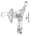
DE 198 42 620 A1 bekannt. - Eine ebenfalls aus dem Stand der Technik, bei BMW Fahrzeugen mit Handschaltgetriebe zum Einsatz kommende Schalteinrichtung ist in
Figur 1 gezeigt. - Eine derartige Schalteinrichtung weist einen Schalthebel auf, der... der an einem sich in einer Fahrzeuglängsrichtung erstreckenden Schaltarm schwenkbar gelagert ist. Ein vorderes bzw. getriebeseitiges Ende des Schaltarms ist schwenkbar um eine Querachse des Fahrzeugs mit einem Getriebegehäuse verbunden. Ein unteres Ende des Schalthebels ist über eine Schaltstange gelenkig mit einer Schaltwelle des Getriebes verbunden, welche zur Betätigung von in dem Schaltgetriebe (nicht dargestellt) vorgesehenen Schaltgabeln vorgesehen ist.
- Ein hinteres, dem Getriebe abgewandtes Ende des Schaltarms ist über ein einzelnes Schiebelager, das in ein Karosserieblech des Fahrzeugs eingeclipst ist, verschieblich gelagert. Das Schiebelager soll bei einem Crash ein Verschieben des Schaltarms um eine vorgegebene Strecke (z. B. ca. 25mm) ermöglichen, ohne dass dadurch die sich an das Verschiebelager anschließenden Karosseriekomponenten beschädigt werden.
- Wie aus
Figur 1 ersichtlich ist, ist das Schalthebellager bzw. ist der Schalthebel im Bereich zwischen dem Schiebelager und dem vorderen Ende des Schaltarms angeordnet. - Bei einer derartigen Lagerung des Schalthebels kann es beim Start des Verbrennungsmotors zu sichtbaren und spürbaren Ausschlägen am Schalthebelknopf kommen. Dies ist insbesondere bei modernen Fahrzeugen, die mit einer Motor-/Stoppautomatik ausgerüstet sind, unerwünscht, da der Motor beim Stopp-and-Go-Verkehr sehr häufig abgestellt und wieder gestartet wird. Zur Verringerung von Ausschlägen und Vibrationen des Schalthebelknopfs wurden daher Schalthebeltilger, die ein Zusatzgewicht von circa 400g aufweisen und ein schwerer Schaltknopf, der gegenüber herkömmlichen Schaltknäufen ein Zusatzgewicht von circa 100g aufweist, verbaut.
- Aufgabe der Erfindung ist es, eine Schalteinrichtung zum Schalten eines Handschaltgetriebes zu schaffen, die so konstruiert ist, dass, im Vergleich zu herkömmlichen Schalteinrichtungen, Vibrationen und Ausschläge des Schalthebelknopfs, insbesondere beim Starten des Motors möglichst gering sind.
- Diese Aufgabe wird durch die Merkmale des Patentanspruches 1 gelöst. Vorteilhafte Ausgestaltungen und Weiterbildungen der Erfindung sind den Unteransprüchen zu entnehmen.
- Ausgangspunkt der Erfindung ist eine Schalteinrichtung zum Schalten eines Handschaltgetriebes eines Fahrzeugs, mit einem Schalthebel, der in einem Schalthebellager eines sich in einer Fahrzeuglängsrichtung erstreckenden Schaltarms schwenkbar gelagert ist. Der Schaltarm weist einen getriebeseitigen (oder vorderen) Endschnitt auf, welcher über eine schaltkräfteabstützende "Koppeleinrichtung" mit einem Getriebegehäuse verbunden ist. Die Schaltkräfte wirken primär in Fahrzeuglängsrichtung. Dementsprechend muss die Koppeleinrichtung so konzipiert sein, dass sie in Fahrzeuglängsrichtung wirkende Kräfte aufnehmen kann.
- Ein zentraler Gedanke der Erfindung besteht darin, dass der Schaltarm über ein linkes und ein rechtes, d.h. über insgesamt zwei, in einer Fahrzeuglängsrichtung verschiebliche Verschiebelager mit einer Karosserie des Fahrzeugs verbunden ist. Die Verschiebelager sind dazu vorgesehen, ein bei einem Verschwenken des Schalthebels um eine Fahrzeuglängsachse bzw. beim Anwählen einzelner Schaltgassen des Handschaltgetriebes über den Schalthebel eingeleitetes Wählmoment abzustützen.
- Die beiden Verschiebelager können in Fahrzeuglängsrichtung betrachtet links bzw. rechts, d. h. auf einander gegenüberliegenden Seiten des Schaltarms angeordnet sein, wodurch sich eine relativ breite Abstützbasis ergibt, über die auch größere Wählmomente problemlos abgestützt werden können.
- Die beiden Verschiebelager können als "Cliplager" ausgebildet sein, d. h. als Lager, die einfach in entsprechende Ausnehmungen der den Schaltarm umgebenden Fahrzeugkarosserie eingesetzt werden können.
- Die beiden Verschiebelager sind in einem Bereich zwischen dem Schalthebel und dem getriebeseitigen Ende des Schaltarms angeordnet woraus sich ein wesentlicher kinematischer Vorteil ergibt, der später im Zusammenhang mit der Zeichnung noch eingehend erläutert wird.
- Ein weiterer wesentlicher Gedanke der Erfindung besteht darin, dass die Koppeleinrichtung den (vorderen bzw. getriebeseitigen) Endbereich des Schaltarms schwenkbar um drei Raumachsen, jedoch translatorisch unverschieblich mit dem Getriebegehäuse verbindet. Im Unterschied zu dem eingangs beschriebenen Stand der Technik werden somit Schwenkbewegungen des Getriebegehäuses, die z. B. beim Starten des Verbrennungsmotor auftreten können, nicht an den Schaltarm weitergeleitet, da der Schaltarm über die Koppeleinrichtung relativ zu dem Getriebegehäuse verschwenkbar ist.
- Die Koppeleinrichtung kann als Kugelgelenk oder durch ein kugelkopfartiges Koppelelement gebildet sein. Prinzipiell sind auch andersartige Koppelelemente, z. B. in der Form eines Karcianelements o. ä., denkbar, welche eine schwenkbare Verbindung des Schaltarms um drei Raumachsen und eine translatorisch unverschiebbare Verbindung des Schaltarms mit dem Getriebegehäuse ermöglichen.
- Im Folgenden wird die Erfindung im Zusammenhang mit der Zeichnung näher erläutert. Es zeigen:
- Figur 2
- eine perspektivische Darstellung einer Schalteinrichtung gemäß der Erfindung;
- Figur 2a
- eine Explosionsdarstellung einer Koppeleinrichtung gemäß der Erfindung;
- Figur 2b
- das dem Schaltarm zugewandte Ende des Getriebegehäuses mit einem daran angeordneten Kugelkopf;
- Figur 3
- eine Detailzeichnung der Schalteinrichtung von der Getriebeunterseite her betrachtet.
-
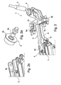
Figur 2 zeigt eine Schalteinrichtung 1 zum Schalten eines Handschaltgetriebes 2. Die Schalteinrichtung 1 weist einen Schalthebel 3 auf, der in einem Schalthebellager 4, welches an einem Schaltarm 5 vorgesehen ist, schwenkbar gelagert ist. Der Schaltarm 5 erstreckt sich im Wesentlichen in einer Fahrzeuglängsrichtung. - Ein dem Handschaltgetriebe 2 zugewandter "vorderer" Endabschnitt 5a des Schaltarms 5 ist über eine Koppeleinrichtung 6 mit einem Gehäuse des Handschaltgetriebes 2 verbunden.
- Die Koppeleinrichtung 6 ist, wie
Figur 2a zu entnehmen ist, durch ein kugelkopfartiges Element 6a und eine Gelenkpfanne 6b gebildet. Die Gelenkpfanne 6b ist hier in eine Ausnehmung des Schaltarms 5 eingesetzt. Das kugelkopfartige Element 6a ist, wieFigur 2b zu entnehmen ist, fest mit dem Getriebegehäuse des Handschaltgetriebes 2 verbunden. Das kugelkopfartige Element 6a und die Gelenkpfanne 6b bilden ein Kugelgelenk. - Über die Koppeleinrichtung 6 ist das vordere Ende 5a des Schaltarms 5 schwenkbar um drei Raumachsen, jedoch translatorisch unverschieblich mit dem Gehäuse des Handschaltgetriebes verbunden. Über die Koppeleinrichtung 6 können somit Schaltkräfte, welche über den Schalthebel 3 in den Schaltarm 5 eingeleitet werden, gegenüber dem Gehäuse des Handschaltgetriebes 2 abgestützt werden. Schwenkbewegungen des Handschaltgetriebes 2, die z. B. beim Starten des Verbrennungsmotors (nicht dargestellt) auftreten können, werden aufgrund der Schwenkfreiheitsgrade der Koppeleinrichtung 6 jedoch nicht bzw. kaum auf den Schaltarm 5 übertragen.
- In einem Bereich zwischen dem Schalthebel 3 und dem getriebeseitigen Ende 5a des Schaltarms 5 ist der Schaltarm 5 über Querlausleger 7a, 7b und über einen damit verbundenes linkes bzw. rechtes in Fahrzeuglängsrichtung verschiebliches Verschiebelager 8a, 8 mit einer Fahrzeugkarosserie (nicht dargestellt) verbunden. Die beiden Verschiebelager 8a, 8b sind dazu vorgesehen, ein bei einem Verschenken des Schalthebels 3 um eine Fahrzeuglängsachse bzw. beim Anwählen einzelner Schaltgassen des Handschaltgetriebes 2 über den Schalthebel 3 eingeleitetes Wählmoment abzustützen. Aufgrund ihres Verschiebefreiheitsgrads ermöglichen sie eine gewisse Relativverschiebung des Schaltarms 5 und des damit verbundenen Getriebegehäuses des Handschaltgetriebes 2 in Fahrzeuglängsrichtung.
- Vollständigkeitshalber sei noch eine Schaltstange 9 erwähnt, über die ein unteres Ende des Schalthebels 3 gelenkig mit einer Schaltwelle 10 des Handschaltgetriebes 2 gekoppelt ist. Über die Schaltwelle 10 können einzelne Gänge des Handschaltgetriebes 2 geschaltet werden.
- Wie bereits erwähnt, sind die beiden Abstützungen 7a, 7b im Bereich zwischen dem Schalthebel 3 und dem Gehäuse des Handschaltgetriebes 2 angeordnet. Die Verschiebelager 7a, 7b sind karosseriefest angeordnet. Kommt es, z. B. bei einem Start des Verbrennungsmotors, zu einem Ruckeln des Handschaltgetriebes, d. h. zu einer seitlichen Verschiebung des Handschaltgetriebes, was in
Figur 3 durch Pfeile 11, 12 angedeutet ist, so überträgt sich diese Verschiebebewegung über die Schaltwelle 10 auf die Schaltstange 9. Da die beiden Abstützungen 7a, 7b im Bereich zwischen dem Schalthebel 3 und dem Gehäuse des Handschaltgetriebes 2 angeordnet sind, kommt es bei einer derartigen seitlichen Verschiebung des Getriebegehäuses zu einer vollständigen oder zumindest teilweisen gegenseitigen Auslöschung der Verschiebebewegungen, was zur Folge hat, dass sich eine seitliche Verschiebung des Gehäuses des Handschaltgetriebes 2 nicht oder nur zu einem geringen Teil bis zum Schalthebel 3 fortpflanzt. - Im Vergleich zu dem eingangs beschriebenen Stand der Technik ergeben sich somit insbesondere beim Starten des Verbrennungsmotors wesentlich geringer Vibrationen bzw. Ausschläge des Schalthebels 3.
Claims (4)
- Schalteinrichtung (1) zum Schalten eines Handschaltgetriebes (2) eines Fahrzeugs, mit- einem Schalthebel (3) und- einem sich in einer Fahrzeuglängsrichtung erstreckenden Schaltarm (5), an dem der Schalthebel (3) schwenkbar gelagert ist, wobei der Schaltarm (5) einen Endabschnitt (5a) aufweist, welcher über eine Schaltkräfte abstützende Koppeleinrichtung (6) mit einem Getriebegehäuse verbunden ist, wobei der Schaltarm (5) über ein linkes und ein rechtes Lager (8a, 8b) mit einer Karosserie des Fahrzeugs verbunden ist, wobei die beiden Lager (8a, 8b) dazu vorgesehen sind, ein bei einem Verschwenken des Schalthebels (3) um eine Fahrzeuglängsachse bzw. beim Anwählen einzelner Schaltgassen des Handschaltgetriebes (2) über den Schalthebel (3) eingeleitetes Wählmoment abzustützen,dadurch gekennzeichnet, dass• es sich bei dem linken und dem rechten Lager (8a, 8b) jeweils um ein in einer Fahrzeuglängsrichtung verschiebliches Verschiebelager (8a, 8b) handelt, wobei• die beiden Verschiebeläger (8a, 8b) in einem zwischen dem Schalthebel (3) und der Koppeleinrichtung (6) befindlichen Bereich auf einander gegenüberliegenden Seiten des Schaltarms (5) angeordnet sind.
- Schalteinrichtung nach Anspruch 1, dadurch gekennzeichnet, dass die Koppeleinrichtung (6) den Endbereich (5a) des Schaltarms (5) schwenkbar um drei Raumachsen, jedoch translatorisch unverschieblich mit dem Getriebegehäuse bindet.
- Schalteinrichtung nach einem der Ansprüche 1 öder 2, dadurch gekennzeichnet, dass die Koppeleinrichtung (6) durch ein Kugelgelenk oder durch ein kugelkopfartiges Koppelelement (6) gebildet ist.
- Schalteinrichtung nach einem der Ansprüche 1 bis 3, dadurch gekennzeichnet, dass der Schalthebel (3) gelenkig über eine Schaltstange (9) mit einer Schaltwelle (10) des Handschaltgetriebes (2) gekoppelt ist.
Applications Claiming Priority (2)
| Application Number | Priority Date | Filing Date | Title |
|---|---|---|---|
| DE201110085902 DE102011085902A1 (de) | 2011-11-08 | 2011-11-08 | Schalteinrichtung zum Schalten eines Handschaltgetriebes eines Fahrzeugs |
| PCT/EP2012/069910 WO2013068187A1 (de) | 2011-11-08 | 2012-10-09 | Schalteinrichtung zum schalten eines handschaltgetriebes eines fahrzeugs |
Publications (2)
| Publication Number | Publication Date |
|---|---|
| EP2776743A1 EP2776743A1 (de) | 2014-09-17 |
| EP2776743B1 true EP2776743B1 (de) | 2015-12-09 |
Family
ID=46982622
Family Applications (1)
| Application Number | Title | Priority Date | Filing Date |
|---|---|---|---|
| EP12769445.3A Active EP2776743B1 (de) | 2011-11-08 | 2012-10-09 | Schalteinrichtung zum schalten eines handschaltgetriebes eines fahrzeugs |
Country Status (3)
| Country | Link |
|---|---|
| EP (1) | EP2776743B1 (de) |
| DE (1) | DE102011085902A1 (de) |
| WO (1) | WO2013068187A1 (de) |
Cited By (1)
| Publication number | Priority date | Publication date | Assignee | Title |
|---|---|---|---|---|
| US10495213B2 (en) | 2017-06-01 | 2019-12-03 | Hyundai Motor Company | Shift lever assembly |
Families Citing this family (3)
| Publication number | Priority date | Publication date | Assignee | Title |
|---|---|---|---|---|
| DE102013204864B4 (de) | 2013-03-20 | 2017-05-04 | Bayerische Motoren Werke Aktiengesellschaft | Schalteinrichtung zum Schalten eines Handschaltgetriebes eines Fahrzeugs |
| CN103912672B (zh) * | 2013-12-20 | 2016-03-30 | 浙江吉利控股集团有限公司 | 曲线滑块换挡器 |
| CN108757926B (zh) * | 2018-07-17 | 2024-01-19 | 一汽解放汽车有限公司 | 一种天线式变速操纵机构 |
Family Cites Families (3)
| Publication number | Priority date | Publication date | Assignee | Title |
|---|---|---|---|---|
| JPS58149523A (ja) * | 1982-03-01 | 1983-09-05 | Nissan Motor Co Ltd | マニユアルトランスミツシヨンのリモ−トコントロ−ル機構 |
| DE19842620A1 (de) * | 1998-01-30 | 2000-04-06 | Daimler Chrysler Ag | Schaltvorrichtung für ein Zahnräderwechselgetriebe |
| DE19803593A1 (de) * | 1998-01-30 | 1999-08-12 | Daimler Chrysler Ag | Schaltvorrichtung für ein Zahnräderwechselgetriebe |
-
2011
- 2011-11-08 DE DE201110085902 patent/DE102011085902A1/de not_active Ceased
-
2012
- 2012-10-09 EP EP12769445.3A patent/EP2776743B1/de active Active
- 2012-10-09 WO PCT/EP2012/069910 patent/WO2013068187A1/de not_active Ceased
Cited By (1)
| Publication number | Priority date | Publication date | Assignee | Title |
|---|---|---|---|---|
| US10495213B2 (en) | 2017-06-01 | 2019-12-03 | Hyundai Motor Company | Shift lever assembly |
Also Published As
| Publication number | Publication date |
|---|---|
| DE102011085902A1 (de) | 2013-05-08 |
| WO2013068187A1 (de) | 2013-05-16 |
| EP2776743A1 (de) | 2014-09-17 |
Similar Documents
| Publication | Publication Date | Title |
|---|---|---|
| EP2240710B1 (de) | Getriebesteller | |
| DE102011101123B4 (de) | Schaltvorrichtung | |
| EP2222985A1 (de) | Rastiersegment für ein übertragungselement in einer schaltvorrichtung sowie schaltvorrichtung mit dem rastiersegment | |
| WO2013068187A1 (de) | Schalteinrichtung zum schalten eines handschaltgetriebes eines fahrzeugs | |
| DE102005001818B4 (de) | Schaltvorrichtung für ein Automatikgetriebe eines Kraftfahrzeuges | |
| DE102007042805A1 (de) | Schaltvorrichtung | |
| EP1267240B1 (de) | Gangwechselvorrichtung für ein handschaltbares Getriebe eines Kraftfahrzeuges | |
| EP2059695B1 (de) | Schaltvorrichtung für kraftfahrzeug-wechselgetriebe | |
| DE102013221356B4 (de) | Schaltvorrichtung | |
| EP2188552B1 (de) | Einrichtung zur rastierung und verriegelung von schaltschwingen einer schalteinrichtung eines getriebes und verwendung einer solchen einrichtung | |
| DE102009041706A1 (de) | Anbindungsvorrichtung für einen Betätigungszug sowie Schaltgetriebe eines Kraftfahrzeugs mit dieser Anbindungsvorrichtung | |
| DE202013011950U1 (de) | Schaltvorrichtung | |
| EP2778480B1 (de) | Fahrzeug mit einer schalthebelanordnung | |
| EP2507536B1 (de) | Schaltelement für ein schaltgetriebe | |
| EP2781794B1 (de) | Schalteinrichtung zum Schalten eines Handschaltgetriebes eines Fahrzeugs | |
| DE102010036389A1 (de) | Schaltanordnung für ein Kraftfahrzeug sowie Kraftfahrzeug | |
| DE4407540B4 (de) | Steuereinrichtung für ein Getriebe | |
| DE10204232B4 (de) | Sperreinrichtung | |
| DE102006028788B4 (de) | Schaltvorrichtung für Geschwindigkeits-Wechselgetriebe in Kraftfahrzeugen | |
| EP1746312B1 (de) | Betätigungsvorrichtung für eine Schaltmuffe | |
| DE10125450A1 (de) | Betätigungsvorrichtung für eine Schaltmuffe sowie Verfahren zum Herstellen einer derartigen Betätigungsvorrichtung | |
| DE102013216483A1 (de) | Fußpedalanordnung | |
| EP2578905B1 (de) | Schaltanordnung für ein Handschaltgetriebe eines Kraftfahrzeugs | |
| DE102013207211B4 (de) | Schalteinrichtung zum Schalten eines Handschaltgetriebes eines Fahrzeugs | |
| DE102011087332A1 (de) | Schalthebelanordnung mit Wählübersetzung |
Legal Events
| Date | Code | Title | Description |
|---|---|---|---|
| PUAI | Public reference made under article 153(3) epc to a published international application that has entered the european phase |
Free format text: ORIGINAL CODE: 0009012 |
|
| 17P | Request for examination filed |
Effective date: 20140319 |
|
| AK | Designated contracting states |
Kind code of ref document: A1 Designated state(s): AL AT BE BG CH CY CZ DE DK EE ES FI FR GB GR HR HU IE IS IT LI LT LU LV MC MK MT NL NO PL PT RO RS SE SI SK SM TR |
|
| DAX | Request for extension of the european patent (deleted) | ||
| GRAP | Despatch of communication of intention to grant a patent |
Free format text: ORIGINAL CODE: EPIDOSNIGR1 |
|
| INTG | Intention to grant announced |
Effective date: 20150721 |
|
| GRAS | Grant fee paid |
Free format text: ORIGINAL CODE: EPIDOSNIGR3 |
|
| GRAA | (expected) grant |
Free format text: ORIGINAL CODE: 0009210 |
|
| AK | Designated contracting states |
Kind code of ref document: B1 Designated state(s): AL AT BE BG CH CY CZ DE DK EE ES FI FR GB GR HR HU IE IS IT LI LT LU LV MC MK MT NL NO PL PT RO RS SE SI SK SM TR |
|
| REG | Reference to a national code |
Ref country code: GB Ref legal event code: FG4D Free format text: NOT ENGLISH |
|
| REG | Reference to a national code |
Ref country code: AT Ref legal event code: REF Ref document number: 764731 Country of ref document: AT Kind code of ref document: T Effective date: 20151215 Ref country code: CH Ref legal event code: EP |
|
| REG | Reference to a national code |
Ref country code: IE Ref legal event code: FG4D Free format text: LANGUAGE OF EP DOCUMENT: GERMAN |
|
| REG | Reference to a national code |
Ref country code: DE Ref legal event code: R096 Ref document number: 502012005447 Country of ref document: DE |
|
| REG | Reference to a national code |
Ref country code: LT Ref legal event code: MG4D |
|
| REG | Reference to a national code |
Ref country code: NL Ref legal event code: MP Effective date: 20151209 |
|
| PG25 | Lapsed in a contracting state [announced via postgrant information from national office to epo] |
Ref country code: NO Free format text: LAPSE BECAUSE OF FAILURE TO SUBMIT A TRANSLATION OF THE DESCRIPTION OR TO PAY THE FEE WITHIN THE PRESCRIBED TIME-LIMIT Effective date: 20160309 Ref country code: LT Free format text: LAPSE BECAUSE OF FAILURE TO SUBMIT A TRANSLATION OF THE DESCRIPTION OR TO PAY THE FEE WITHIN THE PRESCRIBED TIME-LIMIT Effective date: 20151209 Ref country code: ES Free format text: LAPSE BECAUSE OF FAILURE TO SUBMIT A TRANSLATION OF THE DESCRIPTION OR TO PAY THE FEE WITHIN THE PRESCRIBED TIME-LIMIT Effective date: 20151209 |
|
| PG25 | Lapsed in a contracting state [announced via postgrant information from national office to epo] |
Ref country code: LV Free format text: LAPSE BECAUSE OF FAILURE TO SUBMIT A TRANSLATION OF THE DESCRIPTION OR TO PAY THE FEE WITHIN THE PRESCRIBED TIME-LIMIT Effective date: 20151209 Ref country code: SE Free format text: LAPSE BECAUSE OF FAILURE TO SUBMIT A TRANSLATION OF THE DESCRIPTION OR TO PAY THE FEE WITHIN THE PRESCRIBED TIME-LIMIT Effective date: 20151209 Ref country code: GR Free format text: LAPSE BECAUSE OF FAILURE TO SUBMIT A TRANSLATION OF THE DESCRIPTION OR TO PAY THE FEE WITHIN THE PRESCRIBED TIME-LIMIT Effective date: 20160310 Ref country code: RS Free format text: LAPSE BECAUSE OF FAILURE TO SUBMIT A TRANSLATION OF THE DESCRIPTION OR TO PAY THE FEE WITHIN THE PRESCRIBED TIME-LIMIT Effective date: 20151209 Ref country code: NL Free format text: LAPSE BECAUSE OF FAILURE TO SUBMIT A TRANSLATION OF THE DESCRIPTION OR TO PAY THE FEE WITHIN THE PRESCRIBED TIME-LIMIT Effective date: 20151209 Ref country code: FI Free format text: LAPSE BECAUSE OF FAILURE TO SUBMIT A TRANSLATION OF THE DESCRIPTION OR TO PAY THE FEE WITHIN THE PRESCRIBED TIME-LIMIT Effective date: 20151209 |
|
| PG25 | Lapsed in a contracting state [announced via postgrant information from national office to epo] |
Ref country code: IS Free format text: LAPSE BECAUSE OF FAILURE TO SUBMIT A TRANSLATION OF THE DESCRIPTION OR TO PAY THE FEE WITHIN THE PRESCRIBED TIME-LIMIT Effective date: 20151209 |
|
| PG25 | Lapsed in a contracting state [announced via postgrant information from national office to epo] |
Ref country code: CZ Free format text: LAPSE BECAUSE OF FAILURE TO SUBMIT A TRANSLATION OF THE DESCRIPTION OR TO PAY THE FEE WITHIN THE PRESCRIBED TIME-LIMIT Effective date: 20151209 |
|
| PG25 | Lapsed in a contracting state [announced via postgrant information from national office to epo] |
Ref country code: RO Free format text: LAPSE BECAUSE OF FAILURE TO SUBMIT A TRANSLATION OF THE DESCRIPTION OR TO PAY THE FEE WITHIN THE PRESCRIBED TIME-LIMIT Effective date: 20151209 Ref country code: PT Free format text: LAPSE BECAUSE OF FAILURE TO SUBMIT A TRANSLATION OF THE DESCRIPTION OR TO PAY THE FEE WITHIN THE PRESCRIBED TIME-LIMIT Effective date: 20160411 Ref country code: IS Free format text: LAPSE BECAUSE OF FAILURE TO SUBMIT A TRANSLATION OF THE DESCRIPTION OR TO PAY THE FEE WITHIN THE PRESCRIBED TIME-LIMIT Effective date: 20160409 Ref country code: EE Free format text: LAPSE BECAUSE OF FAILURE TO SUBMIT A TRANSLATION OF THE DESCRIPTION OR TO PAY THE FEE WITHIN THE PRESCRIBED TIME-LIMIT Effective date: 20151209 Ref country code: SM Free format text: LAPSE BECAUSE OF FAILURE TO SUBMIT A TRANSLATION OF THE DESCRIPTION OR TO PAY THE FEE WITHIN THE PRESCRIBED TIME-LIMIT Effective date: 20151209 Ref country code: SK Free format text: LAPSE BECAUSE OF FAILURE TO SUBMIT A TRANSLATION OF THE DESCRIPTION OR TO PAY THE FEE WITHIN THE PRESCRIBED TIME-LIMIT Effective date: 20151209 |
|
| REG | Reference to a national code |
Ref country code: DE Ref legal event code: R097 Ref document number: 502012005447 Country of ref document: DE |
|
| PLBE | No opposition filed within time limit |
Free format text: ORIGINAL CODE: 0009261 |
|
| STAA | Information on the status of an ep patent application or granted ep patent |
Free format text: STATUS: NO OPPOSITION FILED WITHIN TIME LIMIT |
|
| REG | Reference to a national code |
Ref country code: FR Ref legal event code: PLFP Year of fee payment: 5 |
|
| PG25 | Lapsed in a contracting state [announced via postgrant information from national office to epo] |
Ref country code: DK Free format text: LAPSE BECAUSE OF FAILURE TO SUBMIT A TRANSLATION OF THE DESCRIPTION OR TO PAY THE FEE WITHIN THE PRESCRIBED TIME-LIMIT Effective date: 20151209 Ref country code: PL Free format text: LAPSE BECAUSE OF FAILURE TO SUBMIT A TRANSLATION OF THE DESCRIPTION OR TO PAY THE FEE WITHIN THE PRESCRIBED TIME-LIMIT Effective date: 20151209 |
|
| 26N | No opposition filed |
Effective date: 20160912 |
|
| PG25 | Lapsed in a contracting state [announced via postgrant information from national office to epo] |
Ref country code: SI Free format text: LAPSE BECAUSE OF FAILURE TO SUBMIT A TRANSLATION OF THE DESCRIPTION OR TO PAY THE FEE WITHIN THE PRESCRIBED TIME-LIMIT Effective date: 20151209 |
|
| PG25 | Lapsed in a contracting state [announced via postgrant information from national office to epo] |
Ref country code: BE Free format text: LAPSE BECAUSE OF NON-PAYMENT OF DUE FEES Effective date: 20161031 |
|
| REG | Reference to a national code |
Ref country code: CH Ref legal event code: PL |
|
| REG | Reference to a national code |
Ref country code: IE Ref legal event code: MM4A |
|
| PG25 | Lapsed in a contracting state [announced via postgrant information from national office to epo] |
Ref country code: CH Free format text: LAPSE BECAUSE OF NON-PAYMENT OF DUE FEES Effective date: 20161031 Ref country code: LI Free format text: LAPSE BECAUSE OF NON-PAYMENT OF DUE FEES Effective date: 20161031 |
|
| PG25 | Lapsed in a contracting state [announced via postgrant information from national office to epo] |
Ref country code: LU Free format text: LAPSE BECAUSE OF NON-PAYMENT OF DUE FEES Effective date: 20161009 |
|
| REG | Reference to a national code |
Ref country code: FR Ref legal event code: PLFP Year of fee payment: 6 |
|
| PG25 | Lapsed in a contracting state [announced via postgrant information from national office to epo] |
Ref country code: IE Free format text: LAPSE BECAUSE OF NON-PAYMENT OF DUE FEES Effective date: 20161009 |
|
| REG | Reference to a national code |
Ref country code: BE Ref legal event code: MM Effective date: 20161031 |
|
| PG25 | Lapsed in a contracting state [announced via postgrant information from national office to epo] |
Ref country code: HU Free format text: LAPSE BECAUSE OF FAILURE TO SUBMIT A TRANSLATION OF THE DESCRIPTION OR TO PAY THE FEE WITHIN THE PRESCRIBED TIME-LIMIT; INVALID AB INITIO Effective date: 20121009 |
|
| PG25 | Lapsed in a contracting state [announced via postgrant information from national office to epo] |
Ref country code: MT Free format text: LAPSE BECAUSE OF FAILURE TO SUBMIT A TRANSLATION OF THE DESCRIPTION OR TO PAY THE FEE WITHIN THE PRESCRIBED TIME-LIMIT Effective date: 20151209 Ref country code: MC Free format text: LAPSE BECAUSE OF FAILURE TO SUBMIT A TRANSLATION OF THE DESCRIPTION OR TO PAY THE FEE WITHIN THE PRESCRIBED TIME-LIMIT Effective date: 20151209 Ref country code: MK Free format text: LAPSE BECAUSE OF FAILURE TO SUBMIT A TRANSLATION OF THE DESCRIPTION OR TO PAY THE FEE WITHIN THE PRESCRIBED TIME-LIMIT Effective date: 20151209 Ref country code: HR Free format text: LAPSE BECAUSE OF FAILURE TO SUBMIT A TRANSLATION OF THE DESCRIPTION OR TO PAY THE FEE WITHIN THE PRESCRIBED TIME-LIMIT Effective date: 20151209 Ref country code: CY Free format text: LAPSE BECAUSE OF FAILURE TO SUBMIT A TRANSLATION OF THE DESCRIPTION OR TO PAY THE FEE WITHIN THE PRESCRIBED TIME-LIMIT Effective date: 20151209 |
|
| PG25 | Lapsed in a contracting state [announced via postgrant information from national office to epo] |
Ref country code: BG Free format text: LAPSE BECAUSE OF FAILURE TO SUBMIT A TRANSLATION OF THE DESCRIPTION OR TO PAY THE FEE WITHIN THE PRESCRIBED TIME-LIMIT Effective date: 20151209 |
|
| REG | Reference to a national code |
Ref country code: FR Ref legal event code: PLFP Year of fee payment: 7 |
|
| PG25 | Lapsed in a contracting state [announced via postgrant information from national office to epo] |
Ref country code: AL Free format text: LAPSE BECAUSE OF FAILURE TO SUBMIT A TRANSLATION OF THE DESCRIPTION OR TO PAY THE FEE WITHIN THE PRESCRIBED TIME-LIMIT Effective date: 20151209 Ref country code: TR Free format text: LAPSE BECAUSE OF FAILURE TO SUBMIT A TRANSLATION OF THE DESCRIPTION OR TO PAY THE FEE WITHIN THE PRESCRIBED TIME-LIMIT Effective date: 20151209 |
|
| REG | Reference to a national code |
Ref country code: AT Ref legal event code: MM01 Ref document number: 764731 Country of ref document: AT Kind code of ref document: T Effective date: 20171009 |
|
| PG25 | Lapsed in a contracting state [announced via postgrant information from national office to epo] |
Ref country code: AT Free format text: LAPSE BECAUSE OF NON-PAYMENT OF DUE FEES Effective date: 20171009 |
|
| P01 | Opt-out of the competence of the unified patent court (upc) registered |
Effective date: 20230502 |
|
| PGFP | Annual fee paid to national office [announced via postgrant information from national office to epo] |
Ref country code: DE Payment date: 20241022 Year of fee payment: 13 |
|
| PGFP | Annual fee paid to national office [announced via postgrant information from national office to epo] |
Ref country code: GB Payment date: 20241024 Year of fee payment: 13 |
|
| PGFP | Annual fee paid to national office [announced via postgrant information from national office to epo] |
Ref country code: FR Payment date: 20241025 Year of fee payment: 13 |
|
| PGFP | Annual fee paid to national office [announced via postgrant information from national office to epo] |
Ref country code: IT Payment date: 20241031 Year of fee payment: 13 |