EP2776853B1 - Vorrichtung zur messung von strömen in leitungen eines ummantelten kabels eines mehrphasigen netzes - Google Patents
Vorrichtung zur messung von strömen in leitungen eines ummantelten kabels eines mehrphasigen netzes Download PDFInfo
- Publication number
- EP2776853B1 EP2776853B1 EP12780511.7A EP12780511A EP2776853B1 EP 2776853 B1 EP2776853 B1 EP 2776853B1 EP 12780511 A EP12780511 A EP 12780511A EP 2776853 B1 EP2776853 B1 EP 2776853B1
- Authority
- EP
- European Patent Office
- Prior art keywords
- sensors
- cable
- current
- matrix
- given
- Prior art date
- Legal status (The legal status is an assumption and is not a legal conclusion. Google has not performed a legal analysis and makes no representation as to the accuracy of the status listed.)
- Not-in-force
Links
Images

Classifications
-
- G—PHYSICS
- G01—MEASURING; TESTING
- G01R—MEASURING ELECTRIC VARIABLES; MEASURING MAGNETIC VARIABLES
- G01R15/00—Details of measuring arrangements of the types provided for in groups G01R17/00 - G01R29/00, G01R33/00 - G01R33/26 or G01R35/00
- G01R15/14—Adaptations providing voltage or current isolation, e.g. for high-voltage or high-current networks
- G01R15/20—Adaptations providing voltage or current isolation, e.g. for high-voltage or high-current networks using galvano-magnetic devices, e.g. Hall-effect devices, i.e. measuring a magnetic field via the interaction between a current and a magnetic field, e.g. magneto resistive or Hall effect devices
- G01R15/207—Constructional details independent of the type of device used
Definitions
- the invention relates to the measurement of current in electrical networks, and in particular the measurement of current in sheathed cables including several conductors.
- sheathed cables and including several separate conductors.
- Each conductor is intended to transmit a respective phase of a polyphase power supply, typically a three-phase power supply.
- the document US 5473244 discloses an apparatus for making non-contact measurements of voltage, current, and power in conductive elements.
- the apparatus includes capacitive sensors for generating a first current in response to a voltage change in a conductive element. Each sensor is positioned in an electric field of the conductive element and is thus coupled to the conductive element by capacitive coupling.
- a reference source controls the capacitive sensor at a reference frequency to induce the flow of a reference current.
- a measurement network is used to calculate the capacitive coupling based on a measurement of the reference current, thereby determining the voltage in the conductive element based on the first current and the capacitive coupling.
- the document WO01 / 50142 discloses a current measuring device for low voltage power switches.
- the measuring device comprises multiple magnetic field sensors arranged around a current-conducting element whose current it is desired to measure.
- the sensors perform a point measurement of the magnetic fields.
- the measuring device further comprises signal processing means configured to receive the current measurement signals from the different magnetic field sensors.
- the positioning and orientation of the various sensors around the conductive element are made in such a way as to optimize the measurement accuracy of the sensors. the measurement accuracy of the sensors.
- the document US2009 / 0048806 discloses a method of diagnosing a butterfly solenoid valve.
- the feed time of a throttle drive motor is determined from signals provided by multiple magnetic sensors attached to a tube housing an engine power cable. This method makes it possible to accurately determine the switching times of the motor supply.
- the document US7755347 discloses a measurement system for determining the electrical current within each of the conductors of a polyphase cable.
- the measurement system comprises magnetic field sensors distributed radially in a ring.
- the ring is intended to surround the cable to be measured.
- the number of magnetic field sensors is a multiple of the number of conductors included in the cable.
- the system first determines for each driver which sensor is closest to it.
- the system selects the measurement of the sensors that are closest to respective drivers. From the knowledge of the cable structure and the positioning of the conductors, it is possible to calculate the intensity in each of these conductors.
- Such a measurement system has drawbacks.
- Such a measurement system has a relative inaccuracy or requires a large number of sensors.
- Such a measurement system also makes it impossible to measure without first knowing very precisely the structure of the cable in which the measurement is made, which is practically impossible in most maintenance operations. The use of such a measurement system is thus extremely limited.
- the measuring device further comprises a memory storing said library of matrices, said memory being accessible by the computing device.
- the measuring device comprises at least six magnetic sensors uniformly distributed around said central orifice.
- the current measuring device further comprises a magnetic shielding, said sensors being arranged between two lateral faces and an outer radial face of said shielding.
- the matrix library comprises several matrices [K] and [K] + for the same given cable configuration, said matrices [K] and [K] + for this same configuration corresponding to different angular positions of the sensors. relative to this cable, the distance between these angular positions being less than or equal to 10 °.
- M is equal to 3.
- At least six magnetic sensors are distributed uniformly around said central orifice.
- the calculation of the residual vector is carried out with several matrices [K] and [K] + for the same given cable configuration, said matrices [K] and [K] + for this same configuration corresponding to different angular positions sensors relative to this cable, the distance between these angular positions being less than or equal to 10 °.
- [K] + is the penrose inverse pseudo matrix of the matrix [K].
- said sensors are arranged in the same plane perpendicular to the axis of the cable.
- the invention proposes to measure the currents in the conductors of a sheathed cable of a polyphase network. For this, there are at least three magnetic field sensors around a section of the cable, the number of sensors being greater than the number of conductors in which it is desired to measure the current.
- the sensors perform a measurement of the magnetic field emitted by the cable.
- the invention makes it possible to measure current in several conductors of a cable inside a sheath, in a safe manner, without requiring interruption of the power supply and without requiring precise knowledge of the structure of this cable. cable.
- the figure 1 is a sectional view of an example of cable 1 for which a measurement by a measuring device according to the invention is particularly advantageous.
- the cable 1 is a cable comprising a number M of conductors, with M at least equal to 2.
- the conductors present inside the cable 1 are not accessible because they are arranged inside a protective sheath 100.
- cable 1 is in this case a cable intended to conduct three-phase current and thus comprises three conductors respectively 110, 120 and 130.
- the conductors 110, 120 and 130 comprise respective leads 112, 122 and 132.
- the conductive wires 112, 122 and 132 are typically made of metal and disposed within respective insulating sheaths 111, 121 and 131. When the cable 1 is traversed by balanced three-phase current, the conductor wires 112, 122 and 132 are traversed by respective currents. out of phase by 120 °.
- the figure 2 is a schematic cross-sectional representation of a current measuring device 3 according to an exemplary embodiment of the invention.
- the figure 3 is an axial sectional view of a measuring ring of the measuring device 3 at a magnetic sensor.
- the current measuring device 3 comprises a measuring ring intended to surround a section of the sheathed cable 1.
- the measurement ring comprises for this purpose a central through hole 312.
- the measuring ring comprises a plurality of distributed magnetic sensors 300 ( advantageously uniformly) around the central orifice 312.
- the measuring ring comprises a number N of magnetic sensors greater than the number of conductors M whose current is to be measured. In this case, the measuring ring comprises 12 magnetic sensors distributed around the axis of the central orifice 312.
- the magnetic sensors 300 are advantageously arranged in the same plane.
- the magnetic sensors 300 can be secured to each other by means of a belt 315.
- the magnetic sensors 300 can be housed inside a magnetic shield 313.
- the magnetic shielding makes it possible to limit the external interference with the magnets. 300. Simulations performed with a shield 313 have established that this shield 313 substantially improves the accuracy of the magnetic field measurement in the presence of external disturbances.
- the shield 313 illustrated advantageously comprises a U-shaped section extending on the periphery of the measuring ring.
- the shield 313 extends on two lateral faces and an outer radial face of the measuring ring.
- the inside of the shield 313 can either be hollowed out or contain a filling material 314 which also holds the sensors 300 in position.
- the filling material 314 is then a material having a relative permeability close to 1, for example a plastic material.
- the filling material 314 may for example be used in the form of a foam.
- the filling material is devoid of ferromagnetic material.
- the sensors 300 may be of any suitable type, for example Hall effect sensors or magneto-impedances.
- the sensors 300 advantageously comprise a sensitivity to the tangential component and / or to the radial component of the magnetic field of the sheathed cable 1.
- the measurement ring advantageously comprises two parts hinged about a hinge 310, making it possible to form an opening for introducing the cable 1 on the opposite side to this hinge 310
- the measuring ring advantageously comprises a clasp 311 making it possible to fix the two articulated parts to one another and thus to maintain in position this measuring ring on a sheathed cable 1 disposed in the orifice 312.
- the measuring device 3 further comprises a computing device 330 connected to the sensors 300 (for the sake of simplification, the connection between the computing device 330 and the sensors 300 is not illustrated).
- the computing device 330 is configured to calculate the currents flowing through the conductors of the cable 1 as a function of the magnetic field measurements made by the sensors 300.
- the measuring device 3 also advantageously comprises a display screen 340 enabling the values to be displayed. current calculated by the device 330.
- a library of matrices [K] and [K] + representative of the configuration of different cables that can be measured, and representative of an angular position of the sensors 300 of the measuring device 3 around each, are generated. of these cable configurations.
- This library of matrices [K] and [K] + can be generated in the laboratory, for example on the basis of finite element simulations of the different cable configurations and different angular positions of the sensors 300 of the measuring device 3 around these cable configurations. If different configurations of measuring rings (different diameters, different numbers of sensors ...) are available for the measuring device 3, each measuring ring configuration will have its own matrix library [K] and [K] + .
- the Biot-Savart law defines the theoretical relationship between the magnetic field B measured by a sensor and the current flowing through a conductor. This relationship is linear in the absence of disturbances magnetic or shielding nearby. This relationship is based on an assumption of substantially straight and infinite drivers.
- B ⁇ r 2. ⁇ . r . I
- this relation makes it possible to determine the intensity crossing the various conductors of the cable 1 as a function of the magnetic field measured by the different sensors.
- each of the N magnetic sensors measures the sum of the magnetic fields generated by the M drivers.
- B 2 K 21 . I 1 + K 22 . I 2 + K 23 . I 3 ... + K 2 M .
- I M ⁇ BN K NOT 1 . I 1 + K NOT 2 . I 2 + K NOT 3 . I 3 ... + K NM .
- I M K 11 . I 1 + K 12 . I 2 + K 13 . I 3 ... + K 1 M .
- B 2 K 21 . I 1 + K 22 . I 2 + K 23 . I 3 ... + K 2 M .
- I M ⁇ BN K NOT 1 . I 1 + K NOT 2 . I 2 + K NOT 3 . I 3 ... + K NM .
- the coefficients Kij depend only on the geometrical parameters and the materials of the sheathed cable 1 and the measuring ring (for example the geometrical rays of the conductors, the positions of the magnetic sensors with respect to the center of the cable, their angular position with respect to the conductors , or their sensitivity to magnetic fields) and the properties of the measurement environment.
- the Kij coefficients can be determined analytically by means of the Biot-Savart relationship.
- the effects of proximity between the conductors of the cable 1 may be neglected due to a relatively small section of these conductors and a working frequency generally of the order of 50 or 60 Hertz. , corresponding to that of a public electricity grid.
- a working frequency generally of the order of 50 or 60 Hertz.
- current measurements can be made for frequencies well above 60 Hz.
- B [K] + is Penrose's pseudo-inverse matrix of the matrix [K].
- the matrices [K] and [K] + may be corrected or calculated taking into account the impact of the shielding 313 on the measurements made by the sensors 300.
- the matrices [K] and [K] + are memorized for the different cable configurations 1 and for the different positions of the sensors 300 around the cable 1, at the end of the various simulations carried out.
- the matrices [K] and [K] + may for example be stored in the computing device 330, or be remotely accessible to this computing device 330.
- [K] and [K] + matrices will advantageously be produced for many angular positions distinct from the sensors 300 with respect to the same cable 1, for example with an angular resolution preferably of less than 10 °, advantageously less than 5 ° and preferentially less than 2 °.
- the angular position of the sensors relative to the cable 1 during measurement will always be very close to an angular position for which matrices [K] and [K] + are available.
- Numerical simulations will be able to generate matrices [K] and [K] + for different configurations of the same cable, for example by taking into account radial or angular positioning errors of the cable conductors, or for errors of centering or deformation. pivoting of the measuring ring with respect to the cable 1.
- the matrix library [K] and [K] + may be established for a set of known cable structures with a high probability of being measured.
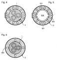
- the sheathed cable 1 is placed in the opening 312 of the measuring device 3, as shown in FIG. figure 4 .
- the sensors 300 then perform one or more samplings of respective magnetic field values.
- the computing device 330 collects the magnetic field values measured by the sensors 300 to form a magnetic field vector [B].
- the computing device 330 thus tests a set of matrices [K] and [K] + stored and potentially representative of the sheathed cable 1 and its position relative to the measuring ring.
- the pair of [K] and [K] + matrices for which the residual vector [R] is minimal is then selected.
- the matrix [K] + is then the most representative of the configuration of the measured cable and the measuring device 3.
- the sensors are shifted at 90 ° around the axis of the cable, the first sensor being disposed at an angle of 0 ° in a given reference frame.
- the conductors are arranged respectively at 0 °, 120 ° and 240 ° around the axis of the cable.
- the conductors are disposed respectively at 30 °, 150 ° and 270 ° around the axis of the cable.
- the conductors are disposed respectively at 60 °, 180 °, and 300 ° around the axis of the cable.
- Simulations were performed with a random angular position of a measuring ring around a cable 1 in a digital model.
- the simulation was performed with about ten sensors distributed homogeneously around the axis of the measuring ring, with a cable having three conductors.
- the sensors 300 of the measuring ring were arranged at a distance of 10 mm from the axis of the cable 1.
- the conductors of the cable 1 were arranged at a distance of 3 mm from this axis.
- Currents of -0.5A, -0.5A and 1A were applied in the conductors of this digital model.
- Sheathed cables 1 of different outside diameters can be measured by current.
- the measuring ring advantageously comprises means of adaptation to different diameters.
- the measuring ring comprises shims 321 and 322 being fixed on its inner wall.
- the shims 321 and 322 thus make it possible to reduce the section of the through orifice 312. With different sets of shims, the measuring ring can thus be fixed on different diameters of sheathed cables, while maintaining a good centering with respect to this cable 1.
Landscapes
- Physics & Mathematics (AREA)
- General Physics & Mathematics (AREA)
- Measuring Instrument Details And Bridges, And Automatic Balancing Devices (AREA)
Claims (11)
- Vorrichtung zur Messung von Strömen (3) in den Leitungen eines ummantelten Kabels eines mehrphasigen Netzes, umfassend:- mindestens drei Magnetsensoren (300), die um eine zentrale Öffnung (312) angeordnet sind, die dazu bestimmt ist, von dem zu messenden Kabel durchquert zu werden, das eine Anzahl von Leitungen aufweist, die niedriger als die Anzahl der Sensoren ist;- eine Rechenvorrichtung (330);dadurch gekennzeichnet, dass die Rechenvorrichtung konfiguriert ist, um:- auf eine Bibliothek von Matrizen [K] und [K]+ zuzugreifen, wobei [I] = [K]+.[B] für eine bestimmte Kabelkonfiguration und eine bestimmte Winkelposition der Sensoren um dieses bestimmte Kabel ist, wobei [I] ein Stromvektor ist, der das Kabel durchquert, das die bestimmte Konfiguration aufweist, wenn ein Magnetfeldvektor [B] an den Sensoren gemessen wird, wobei [K]+ eine pseudoinverse Matrix der Matrix [K] ist;- einen Vektor [B] einschließlich einer Magnetfeldmessung von jedem der Sensoren zu bilden;- für verschiedene Kabelkonfigurationen und verschiedene Winkelpositionen der Sensoren gegenüber diesen Kabeln einen Restvektor [R] = [K]. [K]+.[B]-[B] zu berechnen;- die Matrix [K]+ auszuwählen, für die die Norm des Vektors [R] minimal ist;- [I] = [K]+.[B] zu berechnen, wobei [K]+ die ausgewählte Matrix ist.
- Vorrichtung zur Messung von Strom (3) nach Anspruch 1, die ferner einen Speicher aufweist, der die Matrix-Bibliothek speichert, wobei der Speicher durch die Rechenvorrichtung (330) zugänglich ist.
- Vorrichtung zur Messung von Strom nach Anspruch 1 oder 2, die mindestens sechs Magnetsensoren (300) aufweist, die gleichmäßig um die zentrale Öffnung (312) verteilt sind.
- Vorrichtung zur Messung von Strom (3) nach einem der vorhergehenden Ansprüche, die ferner eine magnetische Abschirmung (313) aufweist, wobei die Sensoren zwischen zwei Seitenflächen und einer radialen Außenfläche der Abschirmung (313) angeordnet sind.
- Vorrichtung zur Messung von Strom (3) nach einem der vorhergehenden Ansprüche, wobei die Matrix-Bibliothek mehrere Matrizen [K] und [K]+ für eine gleiche bestimmte Kabelkonfiguration aufweist, wobei die Matrizen [K] und[K]+ für diese gleiche Konfiguration verschiedenen Winkelpositionen der Sensoren gegenüber diesem Kabel entsprechen, wobei der Abstand zwischen diesen Winkelpositionen weniger als oder gleich 10° beträgt.
- Verfahren zur Messung von Strom in M Leitungen (110, 120, 130) eines ummantelten Kabels (1) eines mehrphasigen Netzes, wobei M mindestens gleich 2 ist, wobei das Verfahren die folgenden Schritte umfasst:- Anordnen von N Magnetsensoren (300) um einen Abschnitt des Kabels (1), wobei N höher als M ist;- Bilden eines Vektors [B] einschließlich der Magnetfeldmessung von jedem der Sensoren;- Berechnen für verschiedene Kabelkonfigurationen und verschiedene Winkelpositionen der N Sensoren (300) gegenüber diesen Kabeln eines Restvektors [R] = [K]. [K]+.[B]-[B], wobei [K] eine Matrize ist, die wie [I] = [K]+.[B] für eine bestimmte Kabelkonfiguration und eine bestimmte Winkelposition der N Sensoren um das bestimmte Kabel definiert ist, wobei [K]+ eine pseudoinverse Matrix der Matrix [K] ist, wobei [I] der Strom ist, der das Kabel der bestimmten Konfiguration mit der bestimmten Winkelposition der N Sensoren durchquert;- Auswählen der Matrix [K]+, für die die Norm des Vektors [R] minimal ist;- Berechnen von [I]=[K]+.[B], wobei [K]+ die ausgewählte Matrix ist.
- Verfahren zur Messung von Strom nach Anspruch 6, wobei M gleich 3 ist.
- Verfahren zur Messung von Strom nach einem der Ansprüche 6 oder 7, wobei mindestens sechs Magnetsensoren (300) gleichmäßig um die zentrale Öffnung (312) verteilt angeordnet werden.
- Verfahren zur Messung von Strom nach einem der Ansprüche 6 bis 8, wobei das Berechnen des Restvektors mit mehreren Matrizen [K] und [K]+ für eine gleiche bestimmte Kabelkonfiguration durchgeführt wird, wobei die Matrizen [K] und [K]+ für diese gleiche Konfiguration verschiedenen Winkelpositionen der Sensoren gegenüber diesem Kabel entsprechen, wobei der Abstand zwischen diesen Winkelpositionen weniger als oder gleich 10° beträgt.
- Verfahren zur Messung von Strom nach einem der Ansprüche 6 bis 9, wobei [K]+ die pseudoinverse Matrix von Penrose der Matrix [K] ist.
- Verfahren zur Messung von Strom nach einem der Ansprüche 6 bis 10, wobei die Sensoren (300) in einer gleichen Ebene senkrecht zu der Achse des Kabels (1) angeordnet sind.
Applications Claiming Priority (2)
| Application Number | Priority Date | Filing Date | Title |
|---|---|---|---|
| FR1103443A FR2982672B1 (fr) | 2011-11-10 | 2011-11-10 | Dispositif de mesure de courants dans les conducteurs d'un cable gaine d'un reseau polyphase |
| PCT/EP2012/071951 WO2013068360A1 (fr) | 2011-11-10 | 2012-11-06 | Dispositif de mesure de courants dans les conducteurs d'un cable gaine d'un reseau polyphase |
Publications (2)
| Publication Number | Publication Date |
|---|---|
| EP2776853A1 EP2776853A1 (de) | 2014-09-17 |
| EP2776853B1 true EP2776853B1 (de) | 2016-10-12 |
Family
ID=47116036
Family Applications (1)
| Application Number | Title | Priority Date | Filing Date |
|---|---|---|---|
| EP12780511.7A Not-in-force EP2776853B1 (de) | 2011-11-10 | 2012-11-06 | Vorrichtung zur messung von strömen in leitungen eines ummantelten kabels eines mehrphasigen netzes |
Country Status (3)
| Country | Link |
|---|---|
| EP (1) | EP2776853B1 (de) |
| FR (1) | FR2982672B1 (de) |
| WO (1) | WO2013068360A1 (de) |
Cited By (2)
| Publication number | Priority date | Publication date | Assignee | Title |
|---|---|---|---|---|
| WO2024121518A1 (fr) * | 2022-12-09 | 2024-06-13 | Nexans | Procédé et dispositif de mesure simultanée de l'intensité du courant dans chaque phase d'un câble électrique polyphasé |
| FR3155594A1 (fr) | 2023-11-21 | 2025-05-23 | Nexans | Support de système de mesure d’au moins un paramètre d’un câble électrique |
Families Citing this family (13)
| Publication number | Priority date | Publication date | Assignee | Title |
|---|---|---|---|---|
| JP6303527B2 (ja) * | 2014-01-21 | 2018-04-04 | 日立金属株式会社 | 電流センサ |
| CH709416B1 (de) * | 2014-03-28 | 2018-05-15 | Phi Sens Gmbh | Verfahren und Vorrichtung für die permanente Strommessung in den Kabel-Verteilkabinen der 230 V/400 V-Netzebene. |
| FR3065289B1 (fr) * | 2017-04-13 | 2019-07-05 | Institut Polytechnique De Grenoble | Procede de mesure de l'intensite d'un courant dans un conducteur |
| US10788517B2 (en) | 2017-11-14 | 2020-09-29 | Analog Devices Global Unlimited Company | Current measuring apparatus and methods |
| US10712369B2 (en) * | 2018-03-23 | 2020-07-14 | Analog Devices Global Unlimted Company | Current measurement using magnetic sensors and contour intervals |
| DE102018116616A1 (de) * | 2018-07-10 | 2020-01-16 | Enlyze GmbH | Verfahren und Vorrichtung zur kontaktlosen, nicht-invasiven Messung von elektrischen Leistungsgrößen |
| EP3686612A1 (de) | 2019-01-22 | 2020-07-29 | Siemens Aktiengesellschaft | Stromsensor mit verbesserter handhabbarkeit |
| DE102020204571A1 (de) * | 2020-04-09 | 2021-10-14 | Robert Bosch Gesellschaft mit beschränkter Haftung | Verfahren zum Messen von Phasenströmen eines Messobjekts, insbesondere eines Inverters |
| CN120615170A (zh) | 2023-01-31 | 2025-09-09 | 传感频谱有限责任公司 | 用于联接到多芯电缆的装置和方法 |
| EP4443173A1 (de) | 2023-04-04 | 2024-10-09 | Pucki GmbH | Verfahren und vorrichtung zur nichtintrusiven strommessung in einem mehrleiterkabel |
| FR3156207B1 (fr) * | 2023-12-05 | 2025-12-12 | Nexans | Procédé et dispositif de mesure simultanée de l’intensité du courant dans chaque phase d’un câble électrique polyphasé |
| FR3156256A1 (fr) | 2023-12-05 | 2025-06-06 | Nexans | Procédé visant à l’équilibrage des phases d’une alimentation en courant électrique polyphasé, et système pour sa mise en œuvre |
| CN119147898A (zh) * | 2024-11-11 | 2024-12-17 | 国网浙江省电力有限公司岱山县供电公司 | 基于量子磁场的三芯电缆中间接头故障定位方法及系统 |
Family Cites Families (7)
| Publication number | Priority date | Publication date | Assignee | Title |
|---|---|---|---|---|
| US5473244A (en) * | 1992-09-17 | 1995-12-05 | Libove; Joel M. | Apparatus for measuring voltages and currents using non-contacting sensors |
| DE4238356A1 (de) * | 1992-11-13 | 1994-05-19 | Abb Patent Gmbh | Verfahren und Einrichtung zur Ermittlung der Leiterströme eines Mehrleitersystems |
| IT1314341B1 (it) * | 1999-12-29 | 2002-12-09 | Abb Ricerca Spa | Dispositivo di misura di corrente per interruttori di potenza di bassatensione |
| WO2006131991A1 (en) * | 2005-06-10 | 2006-12-14 | Shikoku Research Institute Incorporated | Method and apparatus for diagnosis of motor-operated valve |
| FR2872580B1 (fr) * | 2004-06-30 | 2006-09-01 | Valeo Equip Electr Moteur | Procede de mesure du courant electrique dans une pluralite de conducteurs |
| ITMI20041589A1 (it) * | 2004-08-02 | 2004-11-02 | Herholdt Controls S R L | Dispositivo e procedimento per la misura di modulo e fase della corrente che percorre almeno un conduttore |
| US7755347B1 (en) * | 2007-06-12 | 2010-07-13 | Geist Manufacturing Inc. | Current and voltage measurement device |
-
2011
- 2011-11-10 FR FR1103443A patent/FR2982672B1/fr not_active Expired - Fee Related
-
2012
- 2012-11-06 WO PCT/EP2012/071951 patent/WO2013068360A1/fr not_active Ceased
- 2012-11-06 EP EP12780511.7A patent/EP2776853B1/de not_active Not-in-force
Cited By (4)
| Publication number | Priority date | Publication date | Assignee | Title |
|---|---|---|---|---|
| WO2024121518A1 (fr) * | 2022-12-09 | 2024-06-13 | Nexans | Procédé et dispositif de mesure simultanée de l'intensité du courant dans chaque phase d'un câble électrique polyphasé |
| FR3143130A1 (fr) * | 2022-12-09 | 2024-06-14 | Nexans | Procédé et dispositif de mesure simultanée de l’intensité du courant dans chaque phase d’un câble électrique polyphasé |
| FR3155594A1 (fr) | 2023-11-21 | 2025-05-23 | Nexans | Support de système de mesure d’au moins un paramètre d’un câble électrique |
| WO2025109258A1 (fr) | 2023-11-21 | 2025-05-30 | Nexans | Support de système de mesure d'au moins un paramètre d'un câble électrique |
Also Published As
| Publication number | Publication date |
|---|---|
| WO2013068360A1 (fr) | 2013-05-16 |
| FR2982672A1 (fr) | 2013-05-17 |
| FR2982672B1 (fr) | 2014-03-14 |
| EP2776853A1 (de) | 2014-09-17 |
Similar Documents
| Publication | Publication Date | Title |
|---|---|---|
| EP2776853B1 (de) | Vorrichtung zur messung von strömen in leitungen eines ummantelten kabels eines mehrphasigen netzes | |
| EP1977258B1 (de) | Verfahren zur gleichstrommessung mit grosser messungsschwankung, elektronische anordnung mit einer solchen messvorrichtung und vorrichtung zur stromabschaltung mit einer solchen anordnung | |
| FR3048085B1 (fr) | Un accelerometre de levitation magnetique a haute precision | |
| EP2753944B1 (de) | Zeitliches reflektometriesystem und verfahren zur eindeutigen ortung eines elektrischen defekts in einem kabel | |
| WO2014191695A1 (fr) | Dispositif de mesure de tension | |
| FR2463934A1 (fr) | Appareil et procede pour le controle a distance de la position, la vitesse et/ou la direction du mouvement d'un objet mobile | |
| EP1445618A1 (de) | Vorrichtung zur Messung des fliessenden elektrischen Stromes | |
| CA2108185C (fr) | Dispositif support d'une sonde de detection et de localisation de defauts eventuels a l'interieur d'un alesage | |
| EP4414716A1 (de) | Strommessmodul | |
| EP3059597B1 (de) | Vorrichtung zum messen eines elektrischen felds in einem leitermilieu | |
| FR3049351B1 (fr) | Dispositif d'essais de decharges partielles sur les cables | |
| FR2997508A1 (fr) | Harnais et cable comportant une pluralite de capteurs elementaires et procede de surveillance d'un cable et d'un harnais | |
| FR2712663A1 (fr) | Appareil d'inspection de l'état physique de canalisations non accessibles ou visitables par l'homme. | |
| EP0076193B1 (de) | Verfahren zum Bestimmen der Störanfälligkeit elektrischer oder elektronischer Ausrüstung gegen hohe äussere elektromagnetische Felder und Anordnung zur Durchführung des Verfahrens | |
| WO2014180664A1 (fr) | Surcouche destinee a recouvrir un objet, notamment un cable, pour la detection et/ou la localisation d'un defaut a sa surface | |
| EP2583120A1 (de) | Vorrichtung zur überwachung eines kernmaterials in einer handschuhbox | |
| WO2021234240A1 (fr) | Mesure de la tension dans un câble mono-conducteur isolé | |
| FR3109822A1 (fr) | Dispositif capteur de courant et procédé d’assemblage d’un tel dispositif. | |
| EP2956786B1 (de) | Messverfahren und -vorrichtung für magnetresonanzanwendungen | |
| WO2007080304A1 (fr) | Coupe-circuit de batterie comportant des moyens de mesure du courant | |
| FR3156206A1 (fr) | Procédé et dispositif de diagnostic d’un réseau électrique et procédé d’installation associé | |
| WO2011036197A1 (fr) | Procédés et dispositifs de détection de dépôts dans les interstices d'une liaison entre un tube et une plaque | |
| EP4679101A1 (de) | Vorrichtung zur messung des hauptstroms einer elektrischen anlage, messverfahren und schutzverfahren unter verwendung einer solchen vorrichtung | |
| FR3156256A1 (fr) | Procédé visant à l’équilibrage des phases d’une alimentation en courant électrique polyphasé, et système pour sa mise en œuvre | |
| FR3033197A1 (fr) | Tete de mesure hvdc pour capteur de champ magnetique |
Legal Events
| Date | Code | Title | Description |
|---|---|---|---|
| PUAI | Public reference made under article 153(3) epc to a published international application that has entered the european phase |
Free format text: ORIGINAL CODE: 0009012 |
|
| 17P | Request for examination filed |
Effective date: 20140424 |
|
| AK | Designated contracting states |
Kind code of ref document: A1 Designated state(s): AL AT BE BG CH CY CZ DE DK EE ES FI FR GB GR HR HU IE IS IT LI LT LU LV MC MK MT NL NO PL PT RO RS SE SI SK SM TR |
|
| DAX | Request for extension of the european patent (deleted) | ||
| GRAP | Despatch of communication of intention to grant a patent |
Free format text: ORIGINAL CODE: EPIDOSNIGR1 |
|
| RAP1 | Party data changed (applicant data changed or rights of an application transferred) |
Owner name: SOCOMEC Owner name: ELECTRICITE DE FRANCE Owner name: ECOLE CENTRALE DE LYON Owner name: UNIVERSITE LYON 1 CLAUDE BERNARD Owner name: INSTITUT NATIONAL DES SCIENCES APPLIQUEES DE LYON Owner name: KAPTEOS Owner name: CENTRE NATIONAL DE LA RECHERCHE SCIENTIFIQUE |
|
| INTG | Intention to grant announced |
Effective date: 20160503 |
|
| GRAS | Grant fee paid |
Free format text: ORIGINAL CODE: EPIDOSNIGR3 |
|
| GRAA | (expected) grant |
Free format text: ORIGINAL CODE: 0009210 |
|
| AK | Designated contracting states |
Kind code of ref document: B1 Designated state(s): AL AT BE BG CH CY CZ DE DK EE ES FI FR GB GR HR HU IE IS IT LI LT LU LV MC MK MT NL NO PL PT RO RS SE SI SK SM TR |
|
| REG | Reference to a national code |
Ref country code: GB Ref legal event code: FG4D Free format text: NOT ENGLISH |
|
| REG | Reference to a national code |
Ref country code: CH Ref legal event code: EP |
|
| REG | Reference to a national code |
Ref country code: AT Ref legal event code: REF Ref document number: 836989 Country of ref document: AT Kind code of ref document: T Effective date: 20161015 |
|
| REG | Reference to a national code |
Ref country code: IE Ref legal event code: FG4D Free format text: LANGUAGE OF EP DOCUMENT: FRENCH |
|
| REG | Reference to a national code |
Ref country code: DE Ref legal event code: R096 Ref document number: 602012024087 Country of ref document: DE |
|
| REG | Reference to a national code |
Ref country code: FR Ref legal event code: PLFP Year of fee payment: 5 |
|
| REG | Reference to a national code |
Ref country code: LT Ref legal event code: MG4D |
|
| REG | Reference to a national code |
Ref country code: NL Ref legal event code: MP Effective date: 20161012 |
|
| PG25 | Lapsed in a contracting state [announced via postgrant information from national office to epo] |
Ref country code: BE Free format text: LAPSE BECAUSE OF NON-PAYMENT OF DUE FEES Effective date: 20161130 Ref country code: LV Free format text: LAPSE BECAUSE OF FAILURE TO SUBMIT A TRANSLATION OF THE DESCRIPTION OR TO PAY THE FEE WITHIN THE PRESCRIBED TIME-LIMIT Effective date: 20161012 |
|
| REG | Reference to a national code |
Ref country code: AT Ref legal event code: MK05 Ref document number: 836989 Country of ref document: AT Kind code of ref document: T Effective date: 20161012 |
|
| PG25 | Lapsed in a contracting state [announced via postgrant information from national office to epo] |
Ref country code: SE Free format text: LAPSE BECAUSE OF FAILURE TO SUBMIT A TRANSLATION OF THE DESCRIPTION OR TO PAY THE FEE WITHIN THE PRESCRIBED TIME-LIMIT Effective date: 20161012 Ref country code: NO Free format text: LAPSE BECAUSE OF FAILURE TO SUBMIT A TRANSLATION OF THE DESCRIPTION OR TO PAY THE FEE WITHIN THE PRESCRIBED TIME-LIMIT Effective date: 20170112 Ref country code: LT Free format text: LAPSE BECAUSE OF FAILURE TO SUBMIT A TRANSLATION OF THE DESCRIPTION OR TO PAY THE FEE WITHIN THE PRESCRIBED TIME-LIMIT Effective date: 20161012 Ref country code: GR Free format text: LAPSE BECAUSE OF FAILURE TO SUBMIT A TRANSLATION OF THE DESCRIPTION OR TO PAY THE FEE WITHIN THE PRESCRIBED TIME-LIMIT Effective date: 20170113 |
|
| PG25 | Lapsed in a contracting state [announced via postgrant information from national office to epo] |
Ref country code: PL Free format text: LAPSE BECAUSE OF FAILURE TO SUBMIT A TRANSLATION OF THE DESCRIPTION OR TO PAY THE FEE WITHIN THE PRESCRIBED TIME-LIMIT Effective date: 20161012 Ref country code: PT Free format text: LAPSE BECAUSE OF FAILURE TO SUBMIT A TRANSLATION OF THE DESCRIPTION OR TO PAY THE FEE WITHIN THE PRESCRIBED TIME-LIMIT Effective date: 20170213 Ref country code: RS Free format text: LAPSE BECAUSE OF FAILURE TO SUBMIT A TRANSLATION OF THE DESCRIPTION OR TO PAY THE FEE WITHIN THE PRESCRIBED TIME-LIMIT Effective date: 20161012 Ref country code: NL Free format text: LAPSE BECAUSE OF FAILURE TO SUBMIT A TRANSLATION OF THE DESCRIPTION OR TO PAY THE FEE WITHIN THE PRESCRIBED TIME-LIMIT Effective date: 20161012 Ref country code: HR Free format text: LAPSE BECAUSE OF FAILURE TO SUBMIT A TRANSLATION OF THE DESCRIPTION OR TO PAY THE FEE WITHIN THE PRESCRIBED TIME-LIMIT Effective date: 20161012 Ref country code: IS Free format text: LAPSE BECAUSE OF FAILURE TO SUBMIT A TRANSLATION OF THE DESCRIPTION OR TO PAY THE FEE WITHIN THE PRESCRIBED TIME-LIMIT Effective date: 20170212 Ref country code: AT Free format text: LAPSE BECAUSE OF FAILURE TO SUBMIT A TRANSLATION OF THE DESCRIPTION OR TO PAY THE FEE WITHIN THE PRESCRIBED TIME-LIMIT Effective date: 20161012 Ref country code: FI Free format text: LAPSE BECAUSE OF FAILURE TO SUBMIT A TRANSLATION OF THE DESCRIPTION OR TO PAY THE FEE WITHIN THE PRESCRIBED TIME-LIMIT Effective date: 20161012 Ref country code: ES Free format text: LAPSE BECAUSE OF FAILURE TO SUBMIT A TRANSLATION OF THE DESCRIPTION OR TO PAY THE FEE WITHIN THE PRESCRIBED TIME-LIMIT Effective date: 20161012 |
|
| REG | Reference to a national code |
Ref country code: CH Ref legal event code: PL |
|
| REG | Reference to a national code |
Ref country code: DE Ref legal event code: R097 Ref document number: 602012024087 Country of ref document: DE |
|
| PG25 | Lapsed in a contracting state [announced via postgrant information from national office to epo] |
Ref country code: SK Free format text: LAPSE BECAUSE OF FAILURE TO SUBMIT A TRANSLATION OF THE DESCRIPTION OR TO PAY THE FEE WITHIN THE PRESCRIBED TIME-LIMIT Effective date: 20161012 Ref country code: LI Free format text: LAPSE BECAUSE OF NON-PAYMENT OF DUE FEES Effective date: 20161130 Ref country code: CZ Free format text: LAPSE BECAUSE OF FAILURE TO SUBMIT A TRANSLATION OF THE DESCRIPTION OR TO PAY THE FEE WITHIN THE PRESCRIBED TIME-LIMIT Effective date: 20161012 Ref country code: DK Free format text: LAPSE BECAUSE OF FAILURE TO SUBMIT A TRANSLATION OF THE DESCRIPTION OR TO PAY THE FEE WITHIN THE PRESCRIBED TIME-LIMIT Effective date: 20161012 Ref country code: RO Free format text: LAPSE BECAUSE OF FAILURE TO SUBMIT A TRANSLATION OF THE DESCRIPTION OR TO PAY THE FEE WITHIN THE PRESCRIBED TIME-LIMIT Effective date: 20161012 Ref country code: MC Free format text: LAPSE BECAUSE OF FAILURE TO SUBMIT A TRANSLATION OF THE DESCRIPTION OR TO PAY THE FEE WITHIN THE PRESCRIBED TIME-LIMIT Effective date: 20161012 Ref country code: CH Free format text: LAPSE BECAUSE OF NON-PAYMENT OF DUE FEES Effective date: 20161130 Ref country code: EE Free format text: LAPSE BECAUSE OF FAILURE TO SUBMIT A TRANSLATION OF THE DESCRIPTION OR TO PAY THE FEE WITHIN THE PRESCRIBED TIME-LIMIT Effective date: 20161012 |
|
| PLBE | No opposition filed within time limit |
Free format text: ORIGINAL CODE: 0009261 |
|
| STAA | Information on the status of an ep patent application or granted ep patent |
Free format text: STATUS: NO OPPOSITION FILED WITHIN TIME LIMIT |
|
| REG | Reference to a national code |
Ref country code: IE Ref legal event code: MM4A |
|
| PG25 | Lapsed in a contracting state [announced via postgrant information from national office to epo] |
Ref country code: BG Free format text: LAPSE BECAUSE OF FAILURE TO SUBMIT A TRANSLATION OF THE DESCRIPTION OR TO PAY THE FEE WITHIN THE PRESCRIBED TIME-LIMIT Effective date: 20170112 Ref country code: IT Free format text: LAPSE BECAUSE OF FAILURE TO SUBMIT A TRANSLATION OF THE DESCRIPTION OR TO PAY THE FEE WITHIN THE PRESCRIBED TIME-LIMIT Effective date: 20161012 Ref country code: SM Free format text: LAPSE BECAUSE OF FAILURE TO SUBMIT A TRANSLATION OF THE DESCRIPTION OR TO PAY THE FEE WITHIN THE PRESCRIBED TIME-LIMIT Effective date: 20161012 |
|
| 26N | No opposition filed |
Effective date: 20170713 |
|
| PG25 | Lapsed in a contracting state [announced via postgrant information from national office to epo] |
Ref country code: LU Free format text: LAPSE BECAUSE OF NON-PAYMENT OF DUE FEES Effective date: 20161130 |
|
| REG | Reference to a national code |
Ref country code: FR Ref legal event code: PLFP Year of fee payment: 6 |
|
| PG25 | Lapsed in a contracting state [announced via postgrant information from national office to epo] |
Ref country code: SI Free format text: LAPSE BECAUSE OF FAILURE TO SUBMIT A TRANSLATION OF THE DESCRIPTION OR TO PAY THE FEE WITHIN THE PRESCRIBED TIME-LIMIT Effective date: 20161012 Ref country code: IE Free format text: LAPSE BECAUSE OF NON-PAYMENT OF DUE FEES Effective date: 20161106 |
|
| REG | Reference to a national code |
Ref country code: BE Ref legal event code: MM Effective date: 20161130 |
|
| PG25 | Lapsed in a contracting state [announced via postgrant information from national office to epo] |
Ref country code: HU Free format text: LAPSE BECAUSE OF FAILURE TO SUBMIT A TRANSLATION OF THE DESCRIPTION OR TO PAY THE FEE WITHIN THE PRESCRIBED TIME-LIMIT; INVALID AB INITIO Effective date: 20121106 |
|
| PG25 | Lapsed in a contracting state [announced via postgrant information from national office to epo] |
Ref country code: CY Free format text: LAPSE BECAUSE OF FAILURE TO SUBMIT A TRANSLATION OF THE DESCRIPTION OR TO PAY THE FEE WITHIN THE PRESCRIBED TIME-LIMIT Effective date: 20161012 Ref country code: MK Free format text: LAPSE BECAUSE OF FAILURE TO SUBMIT A TRANSLATION OF THE DESCRIPTION OR TO PAY THE FEE WITHIN THE PRESCRIBED TIME-LIMIT Effective date: 20161012 |
|
| PG25 | Lapsed in a contracting state [announced via postgrant information from national office to epo] |
Ref country code: MT Free format text: LAPSE BECAUSE OF FAILURE TO SUBMIT A TRANSLATION OF THE DESCRIPTION OR TO PAY THE FEE WITHIN THE PRESCRIBED TIME-LIMIT Effective date: 20161012 |
|
| PG25 | Lapsed in a contracting state [announced via postgrant information from national office to epo] |
Ref country code: TR Free format text: LAPSE BECAUSE OF FAILURE TO SUBMIT A TRANSLATION OF THE DESCRIPTION OR TO PAY THE FEE WITHIN THE PRESCRIBED TIME-LIMIT Effective date: 20161012 |
|
| PGFP | Annual fee paid to national office [announced via postgrant information from national office to epo] |
Ref country code: DE Payment date: 20181203 Year of fee payment: 7 |
|
| PGFP | Annual fee paid to national office [announced via postgrant information from national office to epo] |
Ref country code: GB Payment date: 20181123 Year of fee payment: 7 Ref country code: FR Payment date: 20181123 Year of fee payment: 7 |
|
| REG | Reference to a national code |
Ref country code: DE Ref legal event code: R119 Ref document number: 602012024087 Country of ref document: DE |
|
| PG25 | Lapsed in a contracting state [announced via postgrant information from national office to epo] |
Ref country code: AL Free format text: LAPSE BECAUSE OF FAILURE TO SUBMIT A TRANSLATION OF THE DESCRIPTION OR TO PAY THE FEE WITHIN THE PRESCRIBED TIME-LIMIT Effective date: 20161012 |
|
| GBPC | Gb: european patent ceased through non-payment of renewal fee |
Effective date: 20191106 |
|
| PG25 | Lapsed in a contracting state [announced via postgrant information from national office to epo] |
Ref country code: DE Free format text: LAPSE BECAUSE OF NON-PAYMENT OF DUE FEES Effective date: 20200603 Ref country code: FR Free format text: LAPSE BECAUSE OF NON-PAYMENT OF DUE FEES Effective date: 20191130 Ref country code: GB Free format text: LAPSE BECAUSE OF NON-PAYMENT OF DUE FEES Effective date: 20191106 |