EP2777433A1 - Elément de siège et système d'armature associé - Google Patents
Elément de siège et système d'armature associé Download PDFInfo
- Publication number
- EP2777433A1 EP2777433A1 EP20130159324 EP13159324A EP2777433A1 EP 2777433 A1 EP2777433 A1 EP 2777433A1 EP 20130159324 EP20130159324 EP 20130159324 EP 13159324 A EP13159324 A EP 13159324A EP 2777433 A1 EP2777433 A1 EP 2777433A1
- Authority
- EP
- European Patent Office
- Prior art keywords
- unit
- relative
- lever
- base
- leg
- Prior art date
- Legal status (The legal status is an assumption and is not a legal conclusion. Google has not performed a legal analysis and makes no representation as to the accuracy of the status listed.)
- Withdrawn
Links
Images






Classifications
-
- A—HUMAN NECESSITIES
- A47—FURNITURE; DOMESTIC ARTICLES OR APPLIANCES; COFFEE MILLS; SPICE MILLS; SUCTION CLEANERS IN GENERAL
- A47C—CHAIRS; SOFAS; BEDS
- A47C7/00—Parts, details, or accessories of chairs or stools
- A47C7/50—Supports for the feet or the legs
-
- A—HUMAN NECESSITIES
- A47—FURNITURE; DOMESTIC ARTICLES OR APPLIANCES; COFFEE MILLS; SPICE MILLS; SUCTION CLEANERS IN GENERAL
- A47C—CHAIRS; SOFAS; BEDS
- A47C7/00—Parts, details, or accessories of chairs or stools
- A47C7/50—Supports for the feet or the legs
- A47C7/506—Supports for the feet or the legs of adjustable type
- A47C7/5066—Supports for the feet or the legs of adjustable type by rotation
- A47C7/5068—Supports for the feet or the legs of adjustable type by rotation actuated by linkages
-
- A—HUMAN NECESSITIES
- A47—FURNITURE; DOMESTIC ARTICLES OR APPLIANCES; COFFEE MILLS; SPICE MILLS; SUCTION CLEANERS IN GENERAL
- A47C—CHAIRS; SOFAS; BEDS
- A47C1/00—Chairs adapted for special purposes
- A47C1/02—Reclining or easy chairs
- A47C1/031—Reclining or easy chairs having coupled concurrently adjustable supporting parts
- A47C1/034—Reclining or easy chairs having coupled concurrently adjustable supporting parts the parts including a leg-rest or foot-rest
- A47C1/035—Reclining or easy chairs having coupled concurrently adjustable supporting parts the parts including a leg-rest or foot-rest in combination with movably-coupled seat and back-rest
- A47C1/0355—Reclining or easy chairs having coupled concurrently adjustable supporting parts the parts including a leg-rest or foot-rest in combination with movably-coupled seat and back-rest actuated by linkages, e.g. lazy-tongs mechanisms
-
- A—HUMAN NECESSITIES
- A47—FURNITURE; DOMESTIC ARTICLES OR APPLIANCES; COFFEE MILLS; SPICE MILLS; SUCTION CLEANERS IN GENERAL
- A47C—CHAIRS; SOFAS; BEDS
- A47C7/00—Parts, details, or accessories of chairs or stools
- A47C7/50—Supports for the feet or the legs
- A47C7/506—Supports for the feet or the legs of adjustable type
Definitions
- the invention relates to a piece of seating furniture with a base fixed in the intended use of the piece of seating furniture, a seat unit with a seat surface, a leg unit movable with respect to the seat unit with a leg support surface and a backrest unit.
- the leg unit is displaceable between a stowage position, in which the leg unit is arranged below the seat surface, and a use position, in which the leg unit is arranged in front of the seat, by means of a movement mechanism.
- the position of the backrest unit relative to the base or the seat unit with the relative movement of the seat unit relative to the base or with the relative movement of the leg unit relative to the seat unit is positively coupled.
- leg unit In order to achieve a sufficiently large leg support surface, there are variants that have a separately movable end segment in addition to the leg unit.
- the leg unit is pivotable relative to the seat unit, in part by means of double-strap mechanisms.
- the leg unit is then usually followed by a pivotable end segment.
- Documents showing such or similar leg segment and end segment designs include, for example BE 100 91 47 A3 , the DE 10 2008 009 234 A1 and the DE 3718645 C2 , In designs that forego an end segment beyond the leg unit, achieving a sufficiently large leg rest area is more difficult to achieve.
- the DE 10 2005 001 877 A1 proposes for this a mechanism in which the leg unit is variable in size. It can thereby be reduced in the transfer from the use position to the stowed position below the seat. Only so it is possible to ensure a sufficient size of the leg support surface in the use position and a sufficient reduction of the leg unit in the pivoted stowed position.
- the object of the invention is to develop a piece of furniture generic type to the effect that this allows the displacement of the leg unit between the stowed position and the use position by means of a simple mechanical design, in particular is desired that the corresponding inventive teaching also in seating furniture pieces with little space under the Seat unit is usable.
- a piece of seating furniture according to the invention provides a sufficiently large leg support surface without having an end segment which can be displaced against it in addition to the leg unit and without the leg unit having to be made variable in size.
- the movement mechanism is designed to transfer the leg unit from the stowage position in which the leg support surface is oriented substantially horizontally into the use position, in which the leg support surface is likewise oriented substantially horizontally.
- the movement mechanism has an intermediate carrier, which is displaceable by means of a pivoting guide relative to the seat unit or the base, wherein the pivoting guide has at least one first pivoting lever between the intermediate carrier and the seat unit or the base.
- a seating piece of furniture is preferably a padded chair or a cushioned sofa.
- this may have several separately movable leg units.
- the notion of high direction means a direction orthogonal to a footprint upon which the furniture stands.
- the indication of the transverse direction means an extension direction which extends horizontally parallel to the front edge of the seat.
- the furniture longitudinal direction is a direction orthogonal to the furniture transverse direction and furniture vertical direction.
- the indications "front” and “rear” refer to the furniture longitudinal direction and refer to the perspective of the person sitting on the piece of furniture, whose legs point forward and whose back points to the rear.
- a state of the piece of furniture is referred to, in which the leg unit is in its stowed position.
- the leg unit As the second use state, a state is referred to, in which the leg unit is arranged in its use position.
- a third state of use in which, when the leg unit is still extended, the backrest is positioned flatter with respect to the second use state.
- Said positive coupling between the backrest unit on the one hand and the base, the seat unit and / or the leg unit on the other hand is such that upon a displacement of the seat unit relative to the base and / or the leg unit relative to the seat unit pivots the backrest, so that a more comfortable seating position at the same time in view of the seating position and the back position is reached.
- the forced coupling does not have to have any effect in every movement phase. Instead, it may also be provided that during a partial displacement of the leg rest or the seat unit relative to the base, the backrest remains positioned unchanged. At least in partial phases of the movement of the leg rest or seat unit, however, the inevitably joint movement must be given.
- the positive coupling is preferably effected by at least one transmission member, which is articulated eccentrically to a pivot axis of the backrest at this and the other end is attached to a movable relative to the base, in particular pivotable, fitting part, which in displacement of the seat unit relative to the base also opposite the base is relocated.
- the first state of use allows a common seating position with feet arranged on the floor.
- the second state of use is also referred to as television position. With raised legs he allows nevertheless a largely upright seating position.
- the third state of use is provided as a lying position.
- the peculiarity of the piece of furniture according to the invention is that it is designed to displace the leg rest largely horizontally.
- the leg rest at least in the stowage position and in the use position, has the essentially horizontal orientation, which is to be understood as meaning that the leg support surface is pivoted by no more than 25 ° relative to an imaginary horizontal plane.
- the leg unit during the entire process of transfer from the stowage position to the use position in this sense is substantially aligned horizontally.
- leg unit makes it possible to use a comparatively large leg unit, since this does not enforce a comparatively high seat height on the seat piece of furniture as a result of its length, as in known designs.
- the length of the legrest in the longitudinal direction may exceed the height of the free space below the seat unit. This also makes it possible to dispense with a separately displaceable relative to the leg unit end segment for extending the leg support surface.
- This movement mechanism has an intermediate carrier which is pivotally provided on the seat unit or the base.
- the base is formed by those parts of the piece of seating furniture, which always remains fixed to a substrate on which the piece of furniture is located when properly transferring the leg unit from the use position to the stowed position and vice versa.
- it is a frame on which also the feet of the furniture are provided. Under a local strength in this sense, a pure rotation is understood.
- the base can thus be designed to be rotatable about a vertical axis by means of a turntable or a functionally comparable unit. Also, a base is considered to be stationary even if it allows a rocking motion against a substrate.
- the seat unit can be movable in the manner explained below.
- the movement of the intermediate carrier along a circular path can alternatively take place relative to the seat unit or the base.
- the intermediate carrier itself serves for the translational guidance of a sliding member, which is thereby displaceable in the longitudinal direction of the furniture.
- levers between the intermediate carrier on the one hand and the base or seat unit on the other hand can be used.
- these levers have a length between their articulation points of not more than 40 cm, preferably not more than 30 cm.
- the sliding guide which allows the movement of the leg unit relative to the intermediate carrier, preferably allows a displacement of the leg unit relative to the intermediate carrier of at least 10 cm, preferably of at least 15 cm.
- a guide of the sliding member relative to the intermediate carrier is to be understood, which is realized in particular by a sliding guide or a roller guide or by another suitable for the production of a translational Relativverlager york guide.
- the displacement of the sliding member relative to the intermediate carrier can serve not only the displacement of the leg unit to the front, but also advantageously allows a pivoting movement of the leg unit relative to the intermediate carrier, which will be explained in more detail depending on the configuration of the seat piece of furniture.
- the carrier With regard to the connection of the intermediate carrier to the seat unit or the base, it is fundamentally conceivable that the carrier as a whole is firmly connected to the first pivot lever and thus follows the pivoting movement with respect to its orientation. It is advantageous, however, if the first pivot lever is articulated on the one hand about a pivot axis pivotally mounted on the seat unit or the base and on the other hand, only a second pivot axis is pivotally articulated to the intermediate carrier. In this way it can be prevented that the intermediate carrier pivots to the same extent, in which this applies to the pivot lever. It can therefore be displaced by the pivot guide in the sense of a largely maintaining horizontal alignment of the leg unit, without significantly changing its orientation.
- positive guidance means are preferably provided by which each pivot position of the first pivot lever relative to the seat unit or relative to the base is caused a pivotal position of the intermediate carrier relative to the first pivot lever.
- Such forced guidance means thus lead to the desired Determination of the movement of the subcarrier.
- this movement is such that the intermediate carrier is pivoted in the transfer position of the leg unit from the stowed position to the use position by not more than 20 °.
- the pivot guide has a second pivot lever which is pivotally mounted about a first pivot axis spaced from the third pivot axis pivotally mounted on the seat unit or the base and on the other hand to a relation to the second pivot axis spaced fourth pivot axis pivotally hinged on pivoting applications.
- the pivot guide is designed as a double lever pivot guide.
- the peculiarity which results from the use of the pivoting guide between the base or seat unit on the one hand and the intermediate support on the other hand and the use of the sliding guide is, in particular, that the intermediate support can for the most part always remain below the seat surface.
- the movement of the intermediate carrier relative to the seat surface or the base is effected by a pivoting guide, which can be hidden very well in front of the user's eyes.
- said pivot lever are provided on the outside of the seat relative to the transverse direction. Mechanical components that extend to the left and right of the seat to the front edge of the seat, are considered to be aesthetically disadvantageous and also form considerable opportunities to injure themselves.
- the movement of the intermediate carrier relative to the seat unit or the base along a circular segment-shaped path indirectly also causes the movement of the sliding member relative to the intermediate carrier.
- the movement of the sliding member takes place in substantially coincident direction with the movement of the intermediate carrier. While the intermediate support is thus displaced to the front to a lesser extent relative to the base or seat unit, the leg unit is simultaneously displaced forward to a greater extent.
- this control lever is preferably mounted about a pivotable in vertical or horizontal axis on the intermediate carrier.
- this arrangement with a vertical or horizontal pivot axis of the control lever causes its pivot points for cooperation with the sliding member on the one hand or the base, the seat unit or a the pivot lever on the other hand takes place along a circular arc shape, so that intermediate lever may be required here.
- the requirement of an intermediate lever may also be required when the slide member is translationally guided along a non-linear path with respect to the intermediate carrier.
- a design with intermediate lever or a sliding guide provided instead is to be understood as articulation of the sliding member to the control lever in the sense of the above statements.
- Such an intermediate lever between the control lever and the sliding member may be formed quite short in a sliding member, which also extends in the use position of the leg rest to below the seat, and only the purpose of balancing between the rotary movement of the control lever and the translational movement of the sliding member serve.
- the sliding member does not extend in the use position of the leg rest to below the seat. This is especially true for designs in which a non-linear translational movement of the slide member relative to the intermediate carrier, in particular with respect to a continuation of the intermediate carrier described below, is provided.
- the intermediate lever which is mounted on the control lever and the sliding member, have a greater extension. It extends in such a case preferably approximately parallel to said extension to the end of the extension arranged Schiebeglied.Der proposed control lever is pivoted by the relative movement of the intermediate carrier relative to the seat unit or the base and transmits this pivotal movement on the sliding guide, whereby the sliding member opposite is displaced to the subcarrier.
- leg rest it is possible to fasten the leg rest to a distal end of the sliding member such that it is no longer movable relative to the sliding member.
- a pivotable articulation of the leg rest on sliding element is advantageous.
- the leg unit can have a pivoting mechanism, wherein this pivoting mechanism is designed to effect a pivoting of the leg unit relative to the sliding member in dependence on the relative position of the sliding member to the extension.
- the extension can also serve to improve the tilt stability of the leg unit.
- sliding member which is non-linearly translationally movable relative to the extension of the intermediate carrier
- the sliding member is in the use position only below the leg support surface, but does not extend to below the seat.
- An active coupling with the pivotal movement of the intermediate carrier relative to the base or the seat unit can be achieved by the intermediate lever already mentioned, which preferably extends substantially parallel to the extension of the intermediate carrier.
- both the extension and the sliding member or the intermediate lever extend between the seat unit and the leg unit and thus in the use position of the leg unit depending on the design of the seat piece of furniture are visible to the user, it is considered particularly advantageous if Surround walls of the extension an interior space within which the sliding member or the slide member leading intermediate lever is movably arranged. Thus, the presence of two relatively movable components for the user is not recognizable. The sliding member or the intermediate lever leading to it is hidden within the extension. In principle, a reverse arrangement is conceivable in which the sliding member defines an interior, within which the extension is arranged. The interior does not have to be completely completed. However, it is regarded in the sense of stability as advantageous if the extension is actually formed as a closed hollow profile, within which the sliding member is sliding or guided by rollers movable.
- the extension and / or the slide member or the intermediate lever are preferably arranged in relation to a transverse direction of the furniture in a Mitteil Scheme which occupies a maximum of one third of the width of the seat. This leads to the aesthetically advantageous design, in which between the seat unit and the leg unit from the outside hardly recognizable, as an inconspicuous pipe.
- the pivoting mechanism which is associated with the leg unit, preferably has a pivotable about a stationary to the sliding member fifth pivot axis pivoting carrier, which is provided fixed to the leg unit.
- this pivoting support that the leg unit relative to the sliding member is only pivotable about a pivot axis stationary relative to sliding member and leg unit.
- the pivoting mechanism has a slotted guide with a slide track and a sliding block, via which the pivot support is operatively coupled to the extension.
- the slotted guide allows a particularly flexible control.
- the slide guide comprises two slide tracks, which are provided in two mutually parallel sheets, which in turn are spaced in the transverse direction of the piece of furniture.
- the slide tracks are preferably non-linear.
- the seat unit is designed to be displaceable relative to the base of the piece of seating furniture, as has already been explained in the introduction.
- the relative movement of the seat unit relative to the base with the relative movement of the pivot carrier relative to the seat unit is preferably operatively coupled.
- the user of the seat piece of furniture according to the invention can thus bring about the transfer of the leg unit from the stowed position to the use position by a displacement of the seat unit relative to the base.
- the displacement of the seat unit relative to the base leads forward to the transfer of the leg unit into the use position.
- the movement of a seat back unit of the furniture is operatively coupled with the movement of the seat unit relative to the base, so that the movement of the seat unit, which leads to the transfer of the leg unit in its use position, or a subsequent movement of the seat unit is followed by a pivoting the backrest unit leads.
- the piece of furniture works like a scale.
- a movement of the seat unit down causes a movement of the leg unit upwards. It is thus used in the transfer of the leg unit between the stowed position and use position, the potential energy of each unit to be lowered and resting on the body part to raise the other unit and resting on body part.
- the user who remains sitting on the piece of furniture, must therefore only a small amount of mechanical energy by muscle power or by a possibly provided motor for electrical displacement.
- the mobility of the seat unit relative to the base is provided by two displacement levers, which are articulated about each spaced pivot axis on the base or a further explained below displacement unit on the one hand and on the seat unit on the other.
- the use of second displacement lever with mutually parallel, but spaced apart pivot axes provides a structurally very simple way to achieve the displaceability of the seat unit relative to the base or the displacement unit available.
- the displacement lever of different lengths and / or are aligned non-parallel, so that takes place in the course of the pivoting movement, a tilting of the seat unit. In the use position of the leg unit, a front edge of the seat is preferably raised.
- the pivot angle of the displacement lever between the base and seat unit are always smaller than the pivot angle of the pivot lever between the seat unit and intermediate carrier.
- the pivot levers pivot between the stowage position of the leg rest and the use position of the leg rest by more than 80 °, while the displacement levers pivot by less than 60 °.
- the leg unit is in its stowage position below the seat unit, preferably at least one of the relocation lever or pivot lever is near a dead center position or even in an over-center position, so that for transferring the leg unit into the use position, at least a slight lifting of the seat unit at least is required in the range of this located in the Kochtot Vietnamese displacement lever.
- an activation lever may be provided, which allows it to leave the dead center by manually applied muscle power.
- At least one of the displacement levers preferably both displacement levers
- the displacement unit serves the purpose of ensuring additional displaceability of the seat unit. This is thus not directly displaced relative to the base, but towards the displacement unit, which in turn can be relocated even to the base. As a result, the seat unit can be moved very far in total between its two extreme positions, which is particularly useful to be able to swing down the backrest of the furniture collision-free far to the rear.
- the displacement unit relative to the base starting from a basic position along a movement path is displaced forward, wherein the movement path is preferably linear or approximately linear.
- the linear movement can preferably be achieved via a sliding system or a lever system.
- An approximately linear movement is understood to mean a movement which, between its starting position and its end position, has a deviation from an imaginary straight line orthogonal to this line, which amounts to a maximum of 20% of the distance between the starting and end positions.
- the displaceability of the displacement unit relative to the base is preferably between 13 cm and 15 cm.
- the movement path of the displacement unit is still considered advantageous if it rises to the front. As a result, a permanent application of force to the displacement unit is brought back to its basic position. If the displacement unit is displaced forward during transfer of the piece of furniture into its third state of use along the movement path, the energy applied for this purpose is partly stored as potential energy. In the return to the second state of use, this energy is available to support the transfer.
- the said lever system for displacing the displacement unit relative to the base is preferably designed such that it has at least one movement lever, which is pivotably articulated to the displacement unit and which in turn is guided by at least two intermediate levers which are pivotally hinged to the base.
- the backrest unit is pivotable about a backrest axis relative to the seat unit, wherein the backrest axis is displaceable with the seat unit relative to the base.
- a backrest guide system is preferably provided by which the backrest unit is pivoted about the backrest axis as a function of the relative position of the seat unit relative to the base and / or the relative position of the displacement unit relative to the base.
- the backrest guiding system leads to a defined Pivoting the backrest. Their position is defined on the one hand by the seat unit side pivot axis. On the other hand, defines the backrest guide system, how far the backrest lowers when moving this pivot axis.
- a backrest guiding system provides that the guidance of the backrest takes place via a connecting link and a link roller or a sliding block guide inserted therein.
- the slide track is stationary on the base, while the slide roller or slotted guide are attached to the back unit.
- the backrest guide system has an eccentric to the backrest axis attached to the backrest unit control lever, which forms a positive coupling to the other moving parts of the furniture.
- the control lever may, in particular, be pivotally mounted on the backrest unit, on the one hand, and pivotally mounted on the base or one of the movement levers of the displacement unit, on the other hand.
- a first and / or a second locking system are provided, wherein the first locking system is designed to block a displacement of the displacement unit relative to the base in the jamming state of the leg unit, and wherein the second locking system is designed therefor to lock in the third state of use, a displacement of the leg unit relative to the seat unit.
- the first and / or the second locking system specify a maximum distance or a minimum distance between two points, one of which is displaced together with the backrest unit and of which the other is displaced together with the leg unit.
- a system has been found in which both locking systems are formed together by two stops, which abut each other both in the first and in the third state of use and thus cause the desired blocking effect.
- Particularly advantageous is the use of a pivotally provided on the backrest tab with a slot whose one end forms one of the stops, while the other stop is formed by a bolt in this slot.
- a spring device is provided on the piece of seating furniture, which, starting from the use position of a transfer of the leg unit in the direction of the stowage position and / or starting from the stowage position, respectively sets a transfer of the leg unit in the direction of the use position. As a result, the stability of the stowed position or the use position is increased.
- the invention further relates to a fitting system for seating furniture pieces, which is designed such that it provides said relative movement between a seat unit on the one hand and a structural unit on the other hand.
- Fig. 1a shows an inventive piece of seating furniture 10, which is designed as a padded chair.
- This seating piece 10 has three mutually movable and respectively padded units, namely a seat unit 12, a leg unit 14 and a backrest unit 16.
- the seat piece of furniture 10 furthermore has a base frame 18 which forms the base of the piece of seating furniture and which is in Fig. 1a is shown in dashed lines.
- the base frame 18 is fixed to a floor 1 and a rear of the seat piece of furniture 10 located wall 2 is arranged.
- the seating furniture 10 has a moving mechanism 20, which is provided by the in Fig. 1 b shown furniture fitting 22 is embodied and which serves the purpose of the relative movement of the seat unit 12 and the leg unit 14 from the stowed position of the Fig. 1a into the use of the Fig. 3a to ensure.
- the furniture fitting 22 has two mounting strips 24 which are fixedly connected to the base frame 18. He also has a present circumferentially closed formed frame 26, which serves in a manner not shown attaching the seat unit 12 and which therefore always together is moved with the seat unit 12. For attachment of the leg unit 14, the fitting 22 moreover has a pivot support 28, which always remains stationary relative to the leg unit 14.
- fitting 22 is connected as explained below.
- Some of the following parts of the fitting 22 are each provided on the left and right sides of the seat and designed to coincide movement. Here, only one of the components is referred to.
- two displacement levers 32, 34 are provided which are each pivotable about a base-side pivot axis 32a, 34a and in each case about a frame-fixed pivot axis 32b, 34b.
- the basic mobility of the seat unit 12 relative to the base frame 18 is given, with the slightly different lever lengths and / or the orientation of the lever in the stowed position of the Fig. 1a
- a tilting movement of the seat unit 12 relative to the base frame 18 is forced in the course of their movement.
- pivoting levers 36, 38 are provided between the frame 26 and an intermediate carrier 30 arranged below the frame, wherein these swivel axles 36c, 38c, which are provided fixedly relative to one another on the intermediate carrier, and swivel axles 36b, 38b provided fixedly on the frame 26 are pivotable.
- a forced operation is also provided between the frame 26 and the intermediate carrier 30.
- the intermediate carrier 30 is movable relative to the frame 26 only along a movement path predetermined by the pivot levers 36, 38. Since the levers have approximately the same length, the movement takes place with only slight tilting of the intermediate carrier 30 relative to the frame 26.
- the relative movement of the frame 26 relative to the base frame 18 and the relative movement of the intermediate carrier 30 relative to the frame 26 are operatively coupled with each other.
- a coupling lever 40 is provided, which is articulated on the one hand on an extension of the displacement lever 32 and on the other hand on the pivot lever 38 pivotally. The result is that the movement of the seat unit 12 relative to the base frame 18 also forces a movement of the intermediate carrier 30 relative to the frame 26. This will be explained below.
- a further extending from the intermediate carrier 30 in the direction of a furniture longitudinal axis 4 forward extension 42 is provided which is formed over its vast length as a hollow tube.
- a U-shaped end portion 44 connects, in each of which two U-legs formed as sheet metal surfaces, a slide track 44a is provided.
- a sliding member 46 is provided within the extension 42 formed as a hollow tube, which is displaceable in the cavity of the hollow tube 42.
- this sliding member 46 is pivotally about a pivot axis 48 of the already mentioned pivot carrier 28 is articulated.
- link slider 28a which extend into the slide tracks 44a. A relative displacement of the sliding member 46 relative to the hollow tube 42 causes the sliding blocks 28a to be displaced along the slide track 44a and thereby cause a pivoting movement of the pivot carrier 28 relative to the hollow tube 42 and the sliding member 46.
- a control lever 50 is provided in order to shift the slide member 46 within the hollow tube.
- This control lever is pivoted about a pivot axis 52 pivotally mounted on the intermediate carrier 30. Its two opposite ends are on the one hand to a Pivoting lever 36 connecting connecting rod 36 d and on the other hand articulated via an intermediate lever 54 on the sliding member 46.
- the intermediate lever 54 acts as a compensating element and makes it possible, by pivoting the control lever 50 about the pivot axis 52, the sliding member 46 deeper into the extension formed as a hollow tube 42 to push in or out of this.
- a moving mechanism which includes full active coupling between all its components.
- FIGS. 1a to 1c In the initial state of FIGS. 1a to 1c in which the leg unit 14 is located below the seat unit 12, the piece of furniture has the function and appearance of a simple chair.
- the displacement lever 34 extends in this state largely vertically, so that a rear end of the seat 12 a assumes its highest possible position.
- the front displacement lever 32 is in this starting position in an over-center position and is angled relative to the vertical.
- the front displacement lever 32 With respect to the perspective of FIG. 1a to turn clockwise. Since this is accompanied by a lifting of a front part of the seat unit 12, on which the weight of the seated person rests, an unintentional displacement of the leg unit 14 is not to be feared.
- the stability the starting position is further reinforced by a spring 56 which is articulated on the pivot levers 36, 38 and which would be stretched at a displacement of the seat unit 12 relative to the base frame 18.
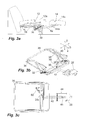
- FIG. 2a The intermediate state reached in this way is in FIG. 2a shown.
- this displacement of the seat unit 12 simultaneously leads to a displacement of the leg unit 14 relative to the seat unit 12.
- This is, guided primarily by the pivot lever 36, 38 largely pivoted forward displaced ,
- the displacement is not limited to that amount which results from the pivot lever 36, 38 and is displaced by the intermediate carrier 30.
- an additional displacement of the sliding member 46 is achieved due to the active coupling of the sliding member 46 with the intermediate carrier 30 and the pivot lever 36 via the control lever 50. This is pushed deeper into the said extension hollow tube 42, wherein it is preferably by this provided rollers easily in this movable.
- the swivel carrier 28 At the opposite end of the swivel carrier is characterized 28, on which the leg unit 40 is attached, additionally displaced in relation to the base position 18 in the longitudinal direction 4 of the furniture. Since the sliding blocks 28a, which may also be designed as rollers, are thereby displaced in the slide guides 44a, pivotal movement of the pivot carrier 28 occurs at the same time.
- the backrest unit 16 can pivot into a comfort position without it coming into contact with the wall 2. This is achieved by the displacement of the seat unit 14.
- the movement of the backrest is positively coupled with the movement of the leg unit.
- the following embodiments illustrate mechanical embodiments for achieving this positive coupling.
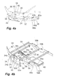
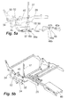
- a second embodiment is in the FIGS. 4 to 6 shown.
- This second embodiment corresponds in terms of their operation largely to the embodiment of FIGS. 1 to 3 , Significant differences exist only in terms of the design of the sliding member 46 and the active coupling of the sliding member 46 and the intermediate carrier 30 on the one hand and with respect to the coupling of the position of the backrest with the relative position of the frame 26 of the seat unit 12 relative to the base and the base-side mounting bar 24 on the other.
- the second embodiment is shown in the figures as well as the other embodiments of FIGS. 7 to 13 illustrated by the respective fitting system. As well as the embodiment of Fig. 1 to 3 All of these embodiments also have a seat unit 12, a leg unit 14 displaceable relative thereto, and a backrest 16. These are in the embodiments of 4 to 13 fixed to the frame 26, mounted on the slide member 46 and on backrest supports 90.
- the seat unit 12, the leg unit 14 and the backrest unit 16 are shown in the illustration 13a of the fourth embodiment. In all other representations of the second to fourth embodiments, these units and the majority of the respective parts of the base are hidden to better understand the operation.
- Fig. 1 to 3 has the embodiment of the 4 to 6 via a seat-unit-side frame 26, which on the one hand can be displaced relative to the base-side attachment strip 24 and, on the other hand, the intermediate support 30 and the sliding member 46 of the leg rest 14 are displaceable.
- the relative mobility of the seat frame 26 relative to the base and the base-side mounting bars 24 is according to the embodiment of Fig. 1 to 3 via two displacement lever 32, 34 allows, which are pivotable about base-side pivot axes 32a, 34a and seat frame-side pivot axes 32b, 34b and by means of which not only the displacement of the seat unit side frame 26 can be achieved forward, but due to sauschlichen spacings of the pivot axes of both displacement lever 32, 34 and a tilting movement of the frame 26th
- the displaceability of the leg unit 14 or of the leg unit 14 stationary sliding member 46 also takes place in this embodiment via a pivotally mounted on the frame 26 intermediate carrier 30 and the given contrast displaceability of the sliding member 46th
- the intermediate carrier 30 is in the case of the embodiment of 4 to 6 primarily formed by a pipe 42 which extends in the longitudinal direction of the piece of furniture and which is displaceable by means of a pivoting guide 36, 38.
- This pivot guide 36, 38 includes two each about U-shaped Pivot levers 36, 38. These are pivotable on the frame 26 about pivot axes 36b, 38b.
- the tube 42 is pivoted about the pivot axes 36c, 38c.
- an asymmetric clevis is mounted, with respect to the perspective of the Fig. 4b rear fork arm 36f defines the front pivot axis 36c.
- This rear fork arm 36f continues to pass into the fixedly connected arm 36g on which the return spring 56 is mounted. The function of the opposite front fork arm 36e will be described later.
- the pivot lever 36, 38 cause a displacement of the tube 42 to the front, wherein due to the different shapes of the pivot lever 36, 38 and the different distance between the respective pivot axes 36 b, 36 c, 38 b, 38 c, the movement of the tube 42 forward simultaneously a light Lifting the front end of the tube 42 is effected.
- the sliding member 46 to which the leg unit 14 is attached, is significantly different from the design of the Fig. 1 to 3 designed and otherwise operatively coupled to the intermediate carrier 30.
- the sliding member 46 of the embodiment of 4 to 6 is designed in the manner of a downwardly open U-shaped profile and does not extend in the extended position of the leg unit 14 to below the seat unit 12. Instead, it does not exceed the leg unit 12.
- the sliding member 46 has in its two profile cheeks via slide tracks 46a. In this slide tracks in each case two slide rollers 42a, 42b are arranged, which are rotatably attached to the front end of the intermediate carrier. Together, the slide tracks 46a and the slide rollers 42a, 42b allow a translational displacement of the slide member 46 opposite the subcarrier.
- a fixed path for this translational displacement is defined by the arrangement of two mutually fixedly spaced gate rollers 42a, 42b.
- the slide tracks 46a could have a linear orientation, so that a linear displaceability of the slide member 46 relative to the intermediate carrier 30 would result. In the present embodiment, however, they have a shape slightly different from the linearity, so that the slide member 46 is tilted slightly forward in the displacement forward relative to the intermediate carrier 30 front side, whereby the lifting of the tube 42 of the intermediate carrier 30 during its movement forward at least partially compensated.
- Fig. 1 to 3 is an active coupling between the relative position of the intermediate carrier 30 to the seat unit side frame 26 and the position of the slide member 46 to the intermediate carrier 30 given.
- This is effected differently from the preceding embodiment via a lever system, which is driven by the relative displacement of the front pivot lever 36 relative to tube 42.
- This lever system has a toggle lever pivotally hinged to the tube 42 about a horizontal transverse axis 57, which is mounted by means of a first pivotable transmission lever 59 on the front fork arm 36e of the front pivot lever 36. If, in the course of pivoting the pivot lever 36, the tube 42 is displaced forward, the toggle lever 57 is characterized based on the perspective of Fig. 4b pivoted clockwise.
- a second transmission lever 58 is pivotally articulated. This extends largely parallel to the tube 42 to the sliding member 46 and is pivotally connected to this in the region of a pivot axis 46b.
- the desired active coupling can be achieved by the lever system described.
- the backrest 16 is fixed in the manner already mentioned on the backrest support 90.
- This backrest support 90 is pivotable relative to the seat unit 12 and its frame 26.
- the relevant pivot axis corresponds in this and the following embodiments of the pivot axis 34b, but could also be formed by a separate and spaced therefrom pivot axis.
- the backrest support 90 is further pivotally hinged to a control lever 92 which is pivotally mounted at the other end to the base-side mounting bar 24. Since the displacement lever 34 and the control lever 92 have a different orientation, they cause a pivoting movement of the backrest support 90 relative to the base, when the displacement lever 34 is pivoted in the course of a displacement of the seat unit 12 relative to the base forward. With the extension of the leg rest and thus the backrest is easily pivoted backwards.
- the embodiment of 4 to 6 has the following active component parts. Opposite the seat unit 12 and the frame 26 of the intermediate carrier 30, starting from the first use position of the Fig. 4a pivoted forward, wherein at the same time by the lever system with the levers 59, 57, 58, a displacement of the sliding member 46 relative to the Intermediate carrier 30 is caused to the front. This displacement of the intermediate carrier 30 and the slide member 46 is caused by a force applied to the seat unit 12 by the occupant sitting on it and / or by a simultaneous actuation of an actuating lever 37. This allows the seat unit 12 are moved to the frame 26 with respect to the base forward , This movement is positively coupled via the coupling lever 40 with the pivotal movement of the intermediate carrier 30. The movement of the seat unit 12 and the frame 26 forward also continues to pivot the backrest 16 in a much flatter and more comfortable position.
- the seat unit 12 with the seat unit side frame 26 and with all the mechanical components of the subcarrier 30, the slide member 46 and the leg unit 14 are identical to the embodiment of FIG 4 to 6 designed so that reference is made to the description there.
- the backrest 16 in the third use position relative to the first use position is not or only slightly displaced further to the rear, so that the piece of furniture in the first use position can be arranged flush with a wall and yet the transfer into the third use position and thereby bedding allowed without the movement of the backrest 16 is obstructed by the wall.
- the displaceability of the seat unit is not limited to that degree that is provided by displacement lever 32, 34.
- a displacement unit 80 is provided, which is provided functionally between the base 18 and the seat unit 12 with frame 26 and which in turn is also displaced forward.
- the displacement unit 80 itself is in the case of the embodiment of Fig. 7 to 9 in addition, even movable towards the base. As a result, a further increased mobility of the seat unit 12 relative to the base is achieved.
- the relative mobility of the displacement unit 80 relative to the base 18 is achieved by two slide tracks 18b, 18c, which are provided in side surfaces of the base 18 and in each of which a guide roller 82a, 82b is used, which are rotatably mounted on the displacement unit.
- the slide tracks 18b, 18c are inclined slightly rising to the front.
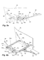
- the lying option is to be made available as the third state of use of the piece of seating furniture, is the coupling of the backrest support 90 to the other components of the seating furniture deviates from the design of the 4 to 6 realized.
- the whereabouts of the guide rollers 82a, 82b in the initial position during the transition to the second state of use Fig. 8a, 8b is on the one hand by the inclined orientation of the slide tracks 18b, 18c conditional.
- a deliberate or unintentional displacement of the displacement unit 80 is in this first transition phase in the second state of use, however, also prevented by the backrest support 90, a tab 94 is pivotally mounted, in which a slot 94 a is provided.
- a slot 94a projects into a bolt 32c, which is provided at the front of the displacement lever 32, 34 and in the first use state of the Fig. 7a and 7b at a the slot 94a end abuts limiting stop area.
- the bolt 32c and the slot 94a thereby prevent the first use state of Fig. 7a, 7b an immediate lowering of the backrest.
- the backrest is therefore at the transition from the first state of use FIGS. 7a, 7b in the second state of use of Fig. 8a, 8b lowered only slightly.
- This small measure is due to the shape an upper portion of the slide track 18a predetermined.
- the pivot axis 34b of the backrest 16 is displaced forward and the backrest 16 guided by the rollers 96 in the slide tracks 18a slightly pivoted.
- a design in which the transfer from the first to the second use state does not cause any pivotal movement of the backrest 16 would be possible by a different shape of the slide tracks 18a in the upper section.
- the piece of furniture can therefore now in the third state of use of Fig. 9a, 9b be transferred, in which the backrest 16 is pivoted much further down.
- This transfer to the third state of use is initiated by the occupant that presses his back against the backrest 16 and / or the seat unit 12 pushes forward.
- FIGS. 10 to 13 is functional to the embodiment of Fig. 7 to 9 very similar. Also the piece of furniture, whose fitting in the FIGS. 10 to 13 is shown for use in a first, second and third use state, again in the first use state, the backrest 16 is retracted and the leg unit 14 is retracted, the leg unit 14 is extended in the second use state and in the third use state with extended leg unit 14, the backrest 16 is significantly pivoted to achieve a reclining position.
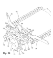
- FIG. 10 shows an exploded view in which the lever system 70 has been replaced by the displacement unit 80 for explanatory purposes.
- the entire assembly consisting of the displacement unit 80, the seating unit 12 pivotally mounted thereto by the displacement levers 32, 34 and the frame 26 and the intermediate support 30 pivotally mounted thereon are functionally almost identical to the sliding member 46 translationally displaceable Design of FIGS. 7 to 9 is trained.
- the additional lever system 70 has a base fixed mounted mounting bar 71, opposite the two movement lever 72, 74 are displaced. These movement levers 72, 74 are each not directly pivotally mounted on the mounting bar, but by means of further intermediate lever, which will be explained below.
- the two movement levers 72, 74 in turn have bores which define pivot axes 72a, 74a, in the region of which the displacement unit 80 is pivotally mounted on the movement levers 72, 74.
- the intermediate lever by means of which the movement lever 72, 74 relative to the mounting bar 71 are defined movable, serve the purpose of ensuring a mobility of the displacement unit 80 relative to the mounting strips, which corresponds approximately to the mobility, which in the embodiment of Fig. 7 to 9 provided by the slide tracks 18b, 18c.
- the intermediate levers ensure an approximately linear mobility.
- This movement lever 74 is mounted by two pivotable intermediate lever 75, 76 on the mounting bar. Of particular importance is the lower intermediate lever 75. This is matched to the movement lever 74 such that the distance between the pivot axis 74a, in the region of which the displacement unit 80 is mounted on the movement lever 74 to the pivot axis 74b to the intermediate lever 75 pivotally on Moving lever 74 is mounted, substantially corresponding to the distance between the pivot axis 74b and the pivot axis 75a to which the intermediate lever 75 is pivotally hinged to the mounting bar 71. At the same time corresponds to the distance between the pivot axis 74b and the pivot axis 74c, by which the intermediate lever 76 is articulated on the movement lever 74, approximately this distance.
- the lever system 70 is thus able to replace the slide tracks 18b, 18c of the previous embodiment. It ensures a nearly identical relative mobility of the displacement unit 80 relative to the base 18.
- this control lever 92 instead mounted pivotally on the rear movement lever 72 about the pivot axis 72d.
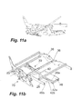
- Fig. 11a and 11b Starting from the first state of use of Fig. 11a and 11b leads a forward displacement of the seat unit 12 with its frame 26 against the initially stationary to each other remaining elements of the displacement unit 80 and the fixed base mounted lever system 70 for extending the leg unit in the same manner as in the previous embodiments.
- Fig. 12a and 12b After reaching the second state of use of Fig. 12a and 12b leads a further forward displacement of the seat unit and a force applied to the backrest and thus the backrest support 90 that due to the active coupling via the control lever 92, the pivot axes 74a, 72a are moved approximately linearly and slightly rising along the dotted line relative to the base fixed mounting bar 71 forward , wherein it comes at the same time to a pivoting of the backrest 16.
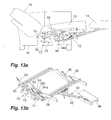
- Fig. 13a, 13b which is the third state of use, allows the seating furniture a comfortable reclining position.
- lever 46, 58, 59 associated with the slide member 46 in particular the lever 58, for the coupling lever 40 for active coupling of the movement of the intermediate carrier 30 with the seat frame 26 and for the control lever 92 for the active coupling of the movement of the seat frame 26 or Displacement unit 80 with the movement of the backrest unit 16.
- a piece of furniture according to the invention can comprise further subunits which are stationary relative to the subunits described or movable separately from them could be. These include in particular armrests, which may preferably be provided fixed to the seat unit.
- the specifically named components which are provided fixedly to the various units, the base, the seat unit, the leg unit and the backrest unit, are to be understood by way of example.
- the mounting strips 24, 71 and the side parts of the base, the seat frame 26, the U-shaped sliding member 46 and the backrest support 90 can be replaced by other components that are suitable for mounting the respective functional elements, in particular lever and slide tracks, without thereby to leave the subject of the invention.
Landscapes
- Health & Medical Sciences (AREA)
- Dentistry (AREA)
- General Health & Medical Sciences (AREA)
- Chairs For Special Purposes, Such As Reclining Chairs (AREA)
- Chair Legs, Seat Parts, And Backrests (AREA)
Priority Applications (2)
| Application Number | Priority Date | Filing Date | Title |
|---|---|---|---|
| US13/800,802 US8985694B2 (en) | 2011-12-28 | 2013-03-13 | Item of seating furniture and fitting therefor |
| EP20130159324 EP2777433A1 (fr) | 2011-12-28 | 2013-03-15 | Elément de siège et système d'armature associé |
Applications Claiming Priority (3)
| Application Number | Priority Date | Filing Date | Title |
|---|---|---|---|
| EP11195967.2A EP2609834B1 (fr) | 2011-12-28 | 2011-12-28 | Elément de siège et système d'armature associé |
| US13/800,802 US8985694B2 (en) | 2011-12-28 | 2013-03-13 | Item of seating furniture and fitting therefor |
| EP20130159324 EP2777433A1 (fr) | 2011-12-28 | 2013-03-15 | Elément de siège et système d'armature associé |
Publications (1)
| Publication Number | Publication Date |
|---|---|
| EP2777433A1 true EP2777433A1 (fr) | 2014-09-17 |
Family
ID=52997791
Family Applications (1)
| Application Number | Title | Priority Date | Filing Date |
|---|---|---|---|
| EP20130159324 Withdrawn EP2777433A1 (fr) | 2011-12-28 | 2013-03-15 | Elément de siège et système d'armature associé |
Country Status (2)
| Country | Link |
|---|---|
| US (1) | US8985694B2 (fr) |
| EP (1) | EP2777433A1 (fr) |
Cited By (1)
| Publication number | Priority date | Publication date | Assignee | Title |
|---|---|---|---|---|
| WO2018033362A1 (fr) * | 2016-08-16 | 2018-02-22 | Vel Vega - Design E Tecnologia Ind. Unip. Lda. | Siège et ferrure associée |
Families Citing this family (10)
| Publication number | Priority date | Publication date | Assignee | Title |
|---|---|---|---|---|
| DE102012214541A1 (de) * | 2012-08-15 | 2014-05-22 | Kintec-Solution Gmbh | Beschlag für ein Sitzmöbelstück |
| US9326606B2 (en) * | 2013-09-19 | 2016-05-03 | La-Z-Boy Incorporated | Furniture member power mechanism with zero gravity and rear tilt positions |
| US10448745B2 (en) * | 2014-03-28 | 2019-10-22 | L&P Property Management Company | Split ottoman linkage with release link |
| US9351576B1 (en) * | 2015-03-05 | 2016-05-31 | L&P Property Management Company | Ottoman linkage mechanism with closing assist |
| US9751631B2 (en) * | 2015-04-23 | 2017-09-05 | PAC Seating Systems, Inc. | Reduced profile legrest for a seat |
| US10653243B2 (en) | 2016-07-29 | 2020-05-19 | Leggett & Platt, Inc. | Rocker/glider recline linkage with projected back pivot point |
| US10420422B2 (en) * | 2016-07-29 | 2019-09-24 | L&P Property Management Company | Recliner chair having improved wall clearance and recline linkage with projected back pivot point |
| US11266245B2 (en) | 2016-07-29 | 2022-03-08 | Leggett & Platt, Inc. | Rocker/glider recliner linkage with projected back pivot point |
| WO2019099389A1 (fr) * | 2017-11-14 | 2019-05-23 | L&P Property Management Company | Tringlerie d'ottomane divisée à liaison de libération |
| US10888136B1 (en) * | 2020-01-13 | 2021-01-12 | Robert A. Deane | Apparatus for assistance in putting on and removing footwear |
Citations (3)
| Publication number | Priority date | Publication date | Assignee | Title |
|---|---|---|---|---|
| US2903045A (en) * | 1956-02-13 | 1959-09-08 | Charles S Viall | Reclining chairs |
| DE29501078U1 (de) * | 1995-01-13 | 1995-04-13 | Frank, Wolfgang, 71540 Murrhardt | Sitzmöbel mit in Gebrauchsstellung bringbarem Fußteil |
| CN102871397A (zh) * | 2011-12-28 | 2013-01-16 | 嘉兴艾纳曼贸易有限公司 | 一种座椅家具装置及其金属构件系统 |
Family Cites Families (17)
| Publication number | Priority date | Publication date | Assignee | Title |
|---|---|---|---|---|
| US1984281A (en) | 1932-11-21 | 1934-12-11 | William H Poggendorf | Chair |
| US2484803A (en) | 1945-09-29 | 1949-10-18 | Heywood Wakefield Co | Retractile leg rest |
| GB850672A (en) | 1959-01-06 | 1960-10-05 | Greaves & Thomas Ltd | Improvements relating to chairs with adjustable leg rests or foot rests |
| US3068047A (en) | 1960-06-13 | 1962-12-11 | Anton Lorenz | Multiple position reclining chair |
| US3039816A (en) | 1960-10-31 | 1962-06-19 | Anton Lorenz | Leg-rest control assembly for multiple position reclining chair |
| US3429612A (en) | 1967-02-20 | 1969-02-25 | William Reginald Cobb | Chairs equipped with legrests or footrests |
| DE2847875C2 (de) | 1978-11-04 | 1980-07-10 | Hans 8904 Friedberg Segmueller Sen. | Polstersessel, mit herausziehbarer, freitragender Fußstütze |
| DE3718645C2 (de) | 1986-08-22 | 1996-07-11 | Appeltshauser Georg Dipl Ing F | Sitzmöbel |
| BE1009147A3 (nl) | 1995-02-20 | 1996-12-03 | Veldeman Group Naamloze Vennoo | Zetel. |
| US6036268A (en) | 1997-09-08 | 2000-03-14 | Larson; John E. | Foot rest mechanism for a work chair |
| DE20000633U1 (de) | 2000-01-14 | 2000-03-09 | Hermann Hummel Polstermöbel GmbH, 96242 Sonnefeld | Sitzmöbel |
| CA2359985A1 (fr) | 2001-10-12 | 2003-04-12 | Viet Pham | Repose-pieds articule a profil bas et fauteuil sur glissieres ainsi equipe |
| US7080887B2 (en) * | 2003-08-14 | 2006-07-25 | Taiwan Shin Yeh Enterprise Co., Ltd. | Chair with foldable leg rest |
| DE102005001877A1 (de) | 2005-01-14 | 2006-07-27 | Deon Ag | Möbel, insbesondere Sitzmöbel |
| DE202008000302U1 (de) | 2008-01-08 | 2008-03-20 | Hesse, Detlef | Beinauflagenbeschlag für ein Möbel |
| DE102008009234A1 (de) | 2008-02-04 | 2009-08-06 | Vel Vega-Design E Tecnologia Ind. Unip. Lda., Funchal | Sitzmöbelstück und Beschlag hierfür |
| DE202010002820U1 (de) | 2010-02-25 | 2010-07-01 | Hesse, Detlef | Beinauflagenbeschlag für ein Möbel |
-
2013
- 2013-03-13 US US13/800,802 patent/US8985694B2/en not_active Expired - Fee Related
- 2013-03-15 EP EP20130159324 patent/EP2777433A1/fr not_active Withdrawn
Patent Citations (4)
| Publication number | Priority date | Publication date | Assignee | Title |
|---|---|---|---|---|
| US2903045A (en) * | 1956-02-13 | 1959-09-08 | Charles S Viall | Reclining chairs |
| DE29501078U1 (de) * | 1995-01-13 | 1995-04-13 | Frank, Wolfgang, 71540 Murrhardt | Sitzmöbel mit in Gebrauchsstellung bringbarem Fußteil |
| CN102871397A (zh) * | 2011-12-28 | 2013-01-16 | 嘉兴艾纳曼贸易有限公司 | 一种座椅家具装置及其金属构件系统 |
| EP2609834A1 (fr) * | 2011-12-28 | 2013-07-03 | Kintec Solution GmbH | Elément de siège et système d'armature associé |
Cited By (6)
| Publication number | Priority date | Publication date | Assignee | Title |
|---|---|---|---|---|
| WO2018033362A1 (fr) * | 2016-08-16 | 2018-02-22 | Vel Vega - Design E Tecnologia Ind. Unip. Lda. | Siège et ferrure associée |
| CN109688876A (zh) * | 2016-08-16 | 2019-04-26 | 维默朗贝斯德管理公司 | 座椅家具和用于座椅家具的配件 |
| US10959524B2 (en) | 2016-08-16 | 2021-03-30 | Beheermaatschappij Vermeulen Beesd B.V. | Piece of seating furniture and fitting therefor |
| CN113017329A (zh) * | 2016-08-16 | 2021-06-25 | 维默朗贝斯德管理公司 | 座椅家具和用于座椅家具的配件 |
| US11044997B2 (en) | 2016-08-16 | 2021-06-29 | Beheermaatschappij Vermeulen Beesd B.V. | Fitting for seating furniture and seating furniture comprising such a fitting |
| CN113017329B (zh) * | 2016-08-16 | 2022-12-27 | 维默朗贝斯德管理公司 | 座椅家具和用于座椅家具的配件 |
Also Published As
| Publication number | Publication date |
|---|---|
| US20130257110A1 (en) | 2013-10-03 |
| US8985694B2 (en) | 2015-03-24 |
Similar Documents
| Publication | Publication Date | Title |
|---|---|---|
| EP2801293B1 (fr) | Elément de siège et sa garniture | |
| EP2609834B1 (fr) | Elément de siège et système d'armature associé | |
| EP2777433A1 (fr) | Elément de siège et système d'armature associé | |
| DE2459908C3 (de) | Ausziehvorrichtung für eine Fußstütze bei einem Lehnsessel | |
| EP2374371B1 (fr) | Meuble destiné à s'assoir doté d'un siège basculant dans une position d'aide à la montée en position debout | |
| EP3965617B1 (fr) | Siège comprenant une fonction wallaway à double moteur | |
| EP2084992A2 (fr) | Elément de siège et sa garniture | |
| DE19830418B4 (de) | Stuhlanordnung | |
| EP3500136B1 (fr) | Armature pour un element de siege et element de siege comprenant une telle armature | |
| DE202016104352U1 (de) | Sitzgelegenheit | |
| DE102009037162B4 (de) | Sitzmöbelstück | |
| DE202004016889U1 (de) | Sitzmöbel | |
| EP2893844B1 (fr) | Siège doté d'un élément de tête pivotant motorisé | |
| DE202005010097U1 (de) | Synchronmechanik | |
| DE202016104973U1 (de) | Gelenkhebelsystem für eine ausschwenkbare Fußstütze eines Sitzmöbels | |
| DE102008005050B4 (de) | Sitzmöbel | |
| EP2544568B1 (fr) | Meuble et ferrure pour un meuble | |
| EP2245964B1 (fr) | Siège doté d'une tringle de couplage reliant un dossier et un pied | |
| DE102017110262A1 (de) | Beinauflagebeschlag für ein Sitz-/Liegemöbel und ein entsprechendes Sitz-/Liegemöbel | |
| EP4374741B1 (fr) | Meuble d'assise | |
| DE19520429B4 (de) | Verstellbares Sitz-/Liegemöbel | |
| EP4585104A1 (fr) | Meuble d'assise | |
| EP4445798A1 (fr) | Meuble d'assise et ferrure de meuble associée | |
| AT503175B1 (de) | Ausziehführungssystem für schubladen | |
| EP4470422A1 (fr) | Meuble d'assise et ferrure associée |
Legal Events
| Date | Code | Title | Description |
|---|---|---|---|
| PUAI | Public reference made under article 153(3) epc to a published international application that has entered the european phase |
Free format text: ORIGINAL CODE: 0009012 |
|
| 17P | Request for examination filed |
Effective date: 20130315 |
|
| AK | Designated contracting states |
Kind code of ref document: A1 Designated state(s): AL AT BE BG CH CY CZ DE DK EE ES FI FR GB GR HR HU IE IS IT LI LT LU LV MC MK MT NL NO PL PT RO RS SE SI SK SM TR |
|
| AX | Request for extension of the european patent |
Extension state: BA ME |
|
| STAA | Information on the status of an ep patent application or granted ep patent |
Free format text: STATUS: THE APPLICATION IS DEEMED TO BE WITHDRAWN |
|
| 18D | Application deemed to be withdrawn |
Effective date: 20150318 |