EP2777445A1 - Ensemble d'entraînement pour rideau - Google Patents
Ensemble d'entraînement pour rideau Download PDFInfo
- Publication number
- EP2777445A1 EP2777445A1 EP13159384.0A EP13159384A EP2777445A1 EP 2777445 A1 EP2777445 A1 EP 2777445A1 EP 13159384 A EP13159384 A EP 13159384A EP 2777445 A1 EP2777445 A1 EP 2777445A1
- Authority
- EP
- European Patent Office
- Prior art keywords
- support
- driving assembly
- connection ring
- transmitting
- portions
- Prior art date
- Legal status (The legal status is an assumption and is not a legal conclusion. Google has not performed a legal analysis and makes no representation as to the accuracy of the status listed.)
- Withdrawn
Links
- 238000009434 installation Methods 0.000 claims abstract description 16
- 238000003780 insertion Methods 0.000 description 4
- 230000037431 insertion Effects 0.000 description 4
- 230000000712 assembly Effects 0.000 description 1
- 238000000429 assembly Methods 0.000 description 1
- 239000011324 bead Substances 0.000 description 1
- 238000000034 method Methods 0.000 description 1
Images


Classifications
-
- E—FIXED CONSTRUCTIONS
- E06—DOORS, WINDOWS, SHUTTERS, OR ROLLER BLINDS IN GENERAL; LADDERS
- E06B—FIXED OR MOVABLE CLOSURES FOR OPENINGS IN BUILDINGS, VEHICLES, FENCES OR LIKE ENCLOSURES IN GENERAL, e.g. DOORS, WINDOWS, BLINDS, GATES
- E06B9/00—Screening or protective devices for wall or similar openings, with or without operating or securing mechanisms; Closures of similar construction
- E06B9/24—Screens or other constructions affording protection against light, especially against sunshine; Similar screens for privacy or appearance; Slat blinds
- E06B9/40—Roller blinds
- E06B9/42—Parts or details of roller blinds, e.g. suspension devices, blind boxes
- E06B9/50—Bearings specially adapted therefor
Definitions
- the present invention relates to a curtain driving assembly, and more particularly, to a curtain driving assembly which is easily assembled and adjusted.
- the driving assembly drives multiple sets of curtains.
- a conventional curtain/roller blind generally includes two supports on two ends thereof and the driving assembly is connected to one of the two supports so as to control the operations of the curtain.
- the driving assembly is connected to one of the two supports so as to control the operations of the curtain.
- Taiwan Patent No. M304304 discloses a curtain driving assembly comprising at least two sets of driving members and a support. Each driving member has a passive member integrally connected with a connection member. The two respective connection members relative to the adjacent driving members are configured in pair and coupled to each other. One of the connection members has an inner gear portion, and the other has an outer gear portion which engaged with the inner gear portion.
- the support has a hole to be pivotably connected with one of the passive members.
- the two driving members are connected to each other in pair, the two driving members have to be precisely and co-axially connected to each other. This requires more assembly techniques and time to assemble the whole curtain driving assembly.
- the present invention intends to provide a curtain driving assembly to improve the shortcomings above mentioned.
- the present invention relates to a curtain driving assembly and comprises a support having an installation hole defined therethrough, and a connection ring is pivotably connected to the installation hole.
- the connection ring has multiple first engaging portions on the inside thereof.
- Two connectors each have a driving portion which is located corresponding to the support.
- Multiple transmitting disks are connected to the driving portions of the two connectors respectively.
- the transmitting disks are connected to the connection ring.
- Each of the transmitting disks has multiple second engaging portions which are engaged with the first engaging portions of the connection ring.
- a bushing is located between the connection ring and the support.
- the bushing has multiple ridges on outside thereof, and the ridges are located corresponding to the periphery of the installation hole of the support.
- the support has a recess defined in the inside of the installation hole.
- the bushing has a insertion on the outside thereof, and the insertion is inserted into the recess.
- a cover has a notch and the support is engaged with the notch.
- a slot is located in the inside of the cover and communicates with the notch, and the transmitting disks and the support are engaged with the slot.
- the support has a rib, and a fixing hole is defined through the cover and communicates with the slot.
- the rib is engaged with the fixing hole.
- connection ring has a contact portion around the inner periphery thereof, and the driving portions of the connectors each have multiple first connection portions.
- the transmitting disks each have multiple second connection portions which are located corresponding to the first connection portions of the driving portion. The transmitting disks contact to the contact portion.
- the first connection portions are protrusions
- the second connection portions are holes which are configured for the first connection portions to engage with.
- the first engaging portion of the connection ring is inner teeth
- the second engaging portions of the transmitting disks are outer teeth.
- one of the transmitting disks has a pivot
- the other transmitting disk has a central hole with which the pivot is pivotably engaged.
- the support has a board which is slidably connected with a base.
- the board has a threaded hole, and an urging member is threadedly connected to the threaded hole and contacts the base.
- One aspect of the present invention is to provide a curtain driving assembly for controlling multiple sets of curtains.
- the cover can be removed and the support is moved toward a lateral side of the base to separate the first engaging portions of one of the transmitting disks from the second engaging portions.
- the pivot on one of the transmitting disks is still engaged with the other transmitting disk. Under this arrangement, when the connector is rotated, the curtain is adjusted.
- Another aspect of the present invention is that the connectors are indirectly rotated by the engagement and transmitting of the inner teeth of the connection ring and the outer teeth of the first engaging portions of the transmitting disks, so that the connectors do not need to be precisely aligned with each other. This reduces the assembling time.
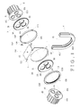
- the curtain driving assembly of the present invention comprises a support 1 having an installation hole 11 and a rib 12.
- a recess 111 is defined in the inside of the support 1 and communicates with the installation hole 11.
- a connection ring 13 is pivotably connected to the installation hole 11 and has multiple first engaging portions 131 on the inside thereof and a contact portion 132.
- the first engaging portions 131 are inner teeth.
- a flange 133 extends from the outside of the connection ring 13 which contacts an end of a bushing 14.
- the bushing 14 is located between the connection ring 13 and the support 1 so as to reduce wearing of the connection ring 13.
- the bushing 14 has multiple ridges 141 on outside thereof, and the ridges 141 are located corresponding to the periphery of the installation hole 11 of the support 1 to form a stop.
- the bushing 14 has an insertion 142 which located on the outside of the bushing 14 and is inserted into the slot 111 to prevent the bushing 14 from rotating.
- the support 1 has a board 15.
- the board 15 has a threaded hole 151, and an urging member 152 is threadedly connected to the threaded hole 151.
- Two connectors 2, 20 each have a driving portion 21 which is located corresponding to the support 1.
- the driving portions 21 of the connectors 2, 20 each have multiple first connection portions 211 which are protrusions.
- Multiple transmitting disks 3, 30 are connected to the driving portions 21 of the two connectors 2, 20 respectively.
- the transmitting disks 3, 30 connected to the connection ring 13.
- Each of the transmitting disks 3, 30 has multiple second engaging portions 31 which are outer teeth and engaged with the inner teeth of the first engaging portions 131 of the connection ring 13.
- the transmitting disks 3, 30 each have multiple second connection portions 32 which are holes and located corresponding to the protrusions of the first connection portions 211 of the driving portion 21.
- One of the transmitting disks 3, 30 contacts to the contact portion 132.
- the transmitting disks 3 has a pivot 33, and the transmitting disk 30 has a central hole 34 with which the pivot 33 is pivotably engaged.
- a cover 4 has a notch 41 and a slot 411 which is located in the inside of the cover 4 and communicates with the notch 41.
- the notch 41 and the slot 411 are configured to accommodate the support 1 and the transmitting disks 3, 30. That is to say, the transmitting disks 3, 30 and the support 1 are installed in the slot 411.
- a fixing hole 412 is defined through the cover 4 and communicates with the slot 411, so that the support 1 is engaged with the cover 4 by engaging the rib 12 with the fixing hole 412.
- the bushing 14 when initially assembling, the bushing 14 is firstly installed to the installation hole 11 of the support 1, and the ridges 141 contacts the support 1 and adjacent to the installation hole 111.
- the insertion 142 is located corresponding to and engaged with the recess 111 of the support 1.
- the connection ring 13 is then installed into the bushing 14 to let the flange 133 of the connection ring 13 to contact the bushing 14. Consequently, the initial assembly of the curtain driving assembly is completed by combining the support 1, the connection ring 13 and the bushing 14 together, as shown in Fig. 2 .
- the connection ring 13 is rotatable relative to the support 1.
- the first connection portions 211 of the connectors 2, 20 are engaged with the second connection portions 32 of the transmitting disks 3, 30 respectively.
- the board 15 is slidably connected to a base 16 which is fixed to the wall, and the urging 152 is rotated toward and contacts to the base 16 so as to fastenly position the support 1 to the base 16.
- the curtain "A” has a scrolling member "B" on one side thereof, and the other side of the curtain “A” is connected to the connector 20 whose transmitting disk 30 is connected to the connection ring 13 to engage the second engaging portions 31 of the transmitting disk 30 with the first engaging portions 131 of the connection ring 13, and the transmitting disk 30 contacts the contact portion 132 (as shown in Fig. 3 ).
- the other connector 2 is connected with the other curtain "A" and the other transmitting disk 3, and the second engaging portions 31 of the transmitting disk 3 are engaged with the first engaging portions 131 of the connection ring 13 (as shown in Figs. 3 and 4 ).
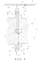
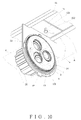
- the cover 4 is installed to accommodate the combination of the support 1, the connection ring 13, the bushing 14 and the transmitting disks 3, 30 within the notch 41 and the slot 411, and the rib 12 of the support 1 is engaged with the fixing hole 412 of the cover 4 (as shown in Figs. 4 to 6 ).
- the curtain driving assembly configured for controlling multiple sets of curtains "A" are assembled.
- the connectors 2, 20 each are respectively cooperated with the transmitting disks 3, 30 whose outer teeth are connected to the inner teeth of the connection ring 13 to form an indirect transmitting relationship. Therefore, the connectors 2, 20 do not need to precisely and co-axially connected to each other.
- the user pulls the bead chain of one of the scrolling member "B", and the corresponding curtain "A” and the corresponding connector 2 or 20 are activated, such that the other curtain "A” is also adjusted concurrently.
- the rotation of the connector 2 drives the transmitting disk 3 to rotate as an integral part of the connector 2 by the connection of the first connection portions 211 and the second connection portion 32.
- the connection ring 13 is driven to rotate by the rotation of the transmitting disk 3.
- the other transmitting disk 30 which is driven by the rotation of the connection ring 30, the other connector 20 which is rotated with the transmitting disk 30, and the other curtain "A" which is rotated with the connector 20 are rotating simultaneously.
- the support 1 is returned to its initial position to be fastenly position to the base 16, and the cover 4 is connected to the support 1.
- the curtain "A” is adjusted without disassembling the curtain "A” and the whole curtain driving assembly, such that the cost time for the adjustment of the uneven scrolled lengths of the curtains is greatly reduced.
Landscapes
- Engineering & Computer Science (AREA)
- Structural Engineering (AREA)
- Architecture (AREA)
- Civil Engineering (AREA)
- Curtains And Furnishings For Windows Or Doors (AREA)
Priority Applications (1)
| Application Number | Priority Date | Filing Date | Title |
|---|---|---|---|
| EP13159384.0A EP2777445A1 (fr) | 2013-03-15 | 2013-03-15 | Ensemble d'entraînement pour rideau |
Applications Claiming Priority (1)
| Application Number | Priority Date | Filing Date | Title |
|---|---|---|---|
| EP13159384.0A EP2777445A1 (fr) | 2013-03-15 | 2013-03-15 | Ensemble d'entraînement pour rideau |
Publications (1)
| Publication Number | Publication Date |
|---|---|
| EP2777445A1 true EP2777445A1 (fr) | 2014-09-17 |
Family
ID=47891477
Family Applications (1)
| Application Number | Title | Priority Date | Filing Date |
|---|---|---|---|
| EP13159384.0A Withdrawn EP2777445A1 (fr) | 2013-03-15 | 2013-03-15 | Ensemble d'entraînement pour rideau |
Country Status (1)
| Country | Link |
|---|---|
| EP (1) | EP2777445A1 (fr) |
Cited By (1)
| Publication number | Priority date | Publication date | Assignee | Title |
|---|---|---|---|---|
| CN116241167A (zh) * | 2021-12-08 | 2023-06-09 | 广州嘉伦橡塑有限公司 | 一种动力组件和卷收窗帘 |
Citations (4)
| Publication number | Priority date | Publication date | Assignee | Title |
|---|---|---|---|---|
| WO2006025681A1 (fr) * | 2004-08-30 | 2006-03-09 | Shin-Young Youn | Grille multiaxiale a rouleaux d'entrainement independants |
| TWM304304U (en) * | 2006-07-10 | 2007-01-11 | Carmelo Joseph Licciar Stefano | Reel linking structure for roll curtain |
| US20080153606A1 (en) * | 2006-12-21 | 2008-06-26 | Hunter Douglas Industries Bv | Adjustable drive coupling for adjacent architectural coverings |
| WO2011117575A1 (fr) * | 2010-03-23 | 2011-09-29 | Louver-Lite Limited | Accouplement pour volets roulants |
-
2013
- 2013-03-15 EP EP13159384.0A patent/EP2777445A1/fr not_active Withdrawn
Patent Citations (4)
| Publication number | Priority date | Publication date | Assignee | Title |
|---|---|---|---|---|
| WO2006025681A1 (fr) * | 2004-08-30 | 2006-03-09 | Shin-Young Youn | Grille multiaxiale a rouleaux d'entrainement independants |
| TWM304304U (en) * | 2006-07-10 | 2007-01-11 | Carmelo Joseph Licciar Stefano | Reel linking structure for roll curtain |
| US20080153606A1 (en) * | 2006-12-21 | 2008-06-26 | Hunter Douglas Industries Bv | Adjustable drive coupling for adjacent architectural coverings |
| WO2011117575A1 (fr) * | 2010-03-23 | 2011-09-29 | Louver-Lite Limited | Accouplement pour volets roulants |
Cited By (1)
| Publication number | Priority date | Publication date | Assignee | Title |
|---|---|---|---|---|
| CN116241167A (zh) * | 2021-12-08 | 2023-06-09 | 广州嘉伦橡塑有限公司 | 一种动力组件和卷收窗帘 |
Similar Documents
| Publication | Publication Date | Title |
|---|---|---|
| US20170022754A1 (en) | Separable tilting device | |
| EP2877066B1 (fr) | Ensemble de montage de stores | |
| US20120031572A1 (en) | Low Profile Roller Shade Control Unit | |
| US9125511B2 (en) | Installation unit of window curtain assembly | |
| US20060243402A1 (en) | Shade roller assembly for shade rollers | |
| US20120085030A1 (en) | Shutter with gear drive for louvres | |
| KR20080058237A (ko) | 인접한 건축용 커버링을 위한 조정가능한 구동 커플링 | |
| JP2009270262A (ja) | 蝶番装置 | |
| KR101318404B1 (ko) | 커튼 승하강 구동장치 | |
| JP6184407B2 (ja) | 日射遮蔽装置、ボトムレールの下限位置調整装置 | |
| US2620866A (en) | Fixture for venetian blinds | |
| AU2013100350A4 (en) | Driving assembly for curtain | |
| US1841384A (en) | Shade-roller | |
| KR200448623Y1 (ko) | 블라인드용 권취구 | |
| US20100122779A1 (en) | Venetian blind | |
| KR200476143Y1 (ko) | 커튼 구동 조립체 | |
| US10407980B2 (en) | Cordless window covering system with bearings | |
| JP6234013B2 (ja) | 日射遮蔽装置 | |
| US10808456B2 (en) | Blind body actuator casing for non-pull cord window blind assembly | |
| US20150121762A1 (en) | Pull cord fixing support for inner and outer windows | |
| US2599884A (en) | Venetian blind tilting mechanism | |
| JP2016211175A (ja) | 日射遮蔽装置の速度調整装置 | |
| EP2695550A1 (fr) | Dispositif de protection contre le rayonnement solaire et dispositif pour le faire fonctionner | |
| KR200397916Y1 (ko) | 커튼 승 하강 구동장치 | |
| CN210087209U (zh) | 卷式窗帘端盖 |
Legal Events
| Date | Code | Title | Description |
|---|---|---|---|
| PUAI | Public reference made under article 153(3) epc to a published international application that has entered the european phase |
Free format text: ORIGINAL CODE: 0009012 |
|
| 17P | Request for examination filed |
Effective date: 20130315 |
|
| AK | Designated contracting states |
Kind code of ref document: A1 Designated state(s): AL AT BE BG CH CY CZ DE DK EE ES FI FR GB GR HR HU IE IS IT LI LT LU LV MC MK MT NL NO PL PT RO RS SE SI SK SM TR |
|
| AX | Request for extension of the european patent |
Extension state: BA ME |
|
| R17P | Request for examination filed (corrected) |
Effective date: 20150119 |
|
| RBV | Designated contracting states (corrected) |
Designated state(s): AL AT BE BG CH CY CZ DE DK EE ES FI FR GB GR HR HU IE IS IT LI LT LU LV MC MK MT NL NO PL PT RO RS SE SI SK SM TR |
|
| GRAP | Despatch of communication of intention to grant a patent |
Free format text: ORIGINAL CODE: EPIDOSNIGR1 |
|
| INTG | Intention to grant announced |
Effective date: 20160303 |
|
| STAA | Information on the status of an ep patent application or granted ep patent |
Free format text: STATUS: THE APPLICATION IS DEEMED TO BE WITHDRAWN |
|
| 18D | Application deemed to be withdrawn |
Effective date: 20160714 |