EP2777580A2 - Bipolare Gasplasmakoagulationsdüse - Google Patents
Bipolare Gasplasmakoagulationsdüse Download PDFInfo
- Publication number
- EP2777580A2 EP2777580A2 EP20140158043 EP14158043A EP2777580A2 EP 2777580 A2 EP2777580 A2 EP 2777580A2 EP 20140158043 EP20140158043 EP 20140158043 EP 14158043 A EP14158043 A EP 14158043A EP 2777580 A2 EP2777580 A2 EP 2777580A2
- Authority
- EP
- European Patent Office
- Prior art keywords
- lumen
- plasma
- elongated body
- electrode
- instrument
- Prior art date
- Legal status (The legal status is an assumption and is not a legal conclusion. Google has not performed a legal analysis and makes no representation as to the accuracy of the status listed.)
- Withdrawn
Links
- 230000015271 coagulation Effects 0.000 title description 7
- 238000005345 coagulation Methods 0.000 title description 7
- 238000004891 communication Methods 0.000 claims abstract description 15
- 239000012530 fluid Substances 0.000 claims abstract description 15
- 230000010287 polarization Effects 0.000 claims description 39
- 230000008878 coupling Effects 0.000 claims description 10
- 238000010168 coupling process Methods 0.000 claims description 10
- 238000005859 coupling reaction Methods 0.000 claims description 10
- 125000006850 spacer group Chemical group 0.000 claims description 3
- 210000002381 plasma Anatomy 0.000 description 123
- 210000001519 tissue Anatomy 0.000 description 23
- 239000002243 precursor Substances 0.000 description 16
- 238000000034 method Methods 0.000 description 13
- 239000003989 dielectric material Substances 0.000 description 12
- 239000007789 gas Substances 0.000 description 11
- -1 tricholoromethane Chemical compound 0.000 description 11
- 239000004020 conductor Substances 0.000 description 10
- 230000004913 activation Effects 0.000 description 9
- 239000000463 material Substances 0.000 description 8
- 230000000694 effects Effects 0.000 description 6
- 239000007788 liquid Substances 0.000 description 6
- 239000002245 particle Substances 0.000 description 6
- 239000002131 composite material Substances 0.000 description 5
- 230000005684 electric field Effects 0.000 description 5
- 239000000203 mixture Substances 0.000 description 5
- 239000000126 substance Substances 0.000 description 5
- IJGRMHOSHXDMSA-UHFFFAOYSA-N Atomic nitrogen Chemical compound N#N IJGRMHOSHXDMSA-UHFFFAOYSA-N 0.000 description 4
- LFQSCWFLJHTTHZ-UHFFFAOYSA-N Ethanol Chemical compound CCO LFQSCWFLJHTTHZ-UHFFFAOYSA-N 0.000 description 4
- 238000013461 design Methods 0.000 description 4
- 238000010586 diagram Methods 0.000 description 4
- 150000002500 ions Chemical class 0.000 description 4
- 230000001225 therapeutic effect Effects 0.000 description 4
- YMWUJEATGCHHMB-UHFFFAOYSA-N Dichloromethane Chemical compound ClCCl YMWUJEATGCHHMB-UHFFFAOYSA-N 0.000 description 3
- LYCAIKOWRPUZTN-UHFFFAOYSA-N Ethylene glycol Chemical compound OCCO LYCAIKOWRPUZTN-UHFFFAOYSA-N 0.000 description 3
- MHAJPDPJQMAIIY-UHFFFAOYSA-N Hydrogen peroxide Chemical compound OO MHAJPDPJQMAIIY-UHFFFAOYSA-N 0.000 description 3
- OKKJLVBELUTLKV-UHFFFAOYSA-N Methanol Chemical compound OC OKKJLVBELUTLKV-UHFFFAOYSA-N 0.000 description 3
- DNIAPMSPPWPWGF-UHFFFAOYSA-N Propylene glycol Chemical compound CC(O)CO DNIAPMSPPWPWGF-UHFFFAOYSA-N 0.000 description 3
- VYPSYNLAJGMNEJ-UHFFFAOYSA-N Silicium dioxide Chemical compound O=[Si]=O VYPSYNLAJGMNEJ-UHFFFAOYSA-N 0.000 description 3
- HEMHJVSKTPXQMS-UHFFFAOYSA-M Sodium hydroxide Chemical compound [OH-].[Na+] HEMHJVSKTPXQMS-UHFFFAOYSA-M 0.000 description 3
- 230000005284 excitation Effects 0.000 description 3
- 230000005281 excited state Effects 0.000 description 3
- 230000007246 mechanism Effects 0.000 description 3
- 229910052751 metal Inorganic materials 0.000 description 3
- 239000002184 metal Substances 0.000 description 3
- 238000003860 storage Methods 0.000 description 3
- 238000012546 transfer Methods 0.000 description 3
- XKRFYHLGVUSROY-UHFFFAOYSA-N Argon Chemical compound [Ar] XKRFYHLGVUSROY-UHFFFAOYSA-N 0.000 description 2
- CURLTUGMZLYLDI-UHFFFAOYSA-N Carbon dioxide Chemical compound O=C=O CURLTUGMZLYLDI-UHFFFAOYSA-N 0.000 description 2
- RTZKZFJDLAIYFH-UHFFFAOYSA-N Diethyl ether Chemical compound CCOCC RTZKZFJDLAIYFH-UHFFFAOYSA-N 0.000 description 2
- XPDWGBQVDMORPB-UHFFFAOYSA-N Fluoroform Chemical compound FC(F)F XPDWGBQVDMORPB-UHFFFAOYSA-N 0.000 description 2
- UQSXHKLRYXJYBZ-UHFFFAOYSA-N Iron oxide Chemical compound [Fe]=O UQSXHKLRYXJYBZ-UHFFFAOYSA-N 0.000 description 2
- KFZMGEQAYNKOFK-UHFFFAOYSA-N Isopropanol Chemical compound CC(C)O KFZMGEQAYNKOFK-UHFFFAOYSA-N 0.000 description 2
- KWYUFKZDYYNOTN-UHFFFAOYSA-M Potassium hydroxide Chemical compound [OH-].[K+] KWYUFKZDYYNOTN-UHFFFAOYSA-M 0.000 description 2
- 239000000853 adhesive Substances 0.000 description 2
- 230000001070 adhesive effect Effects 0.000 description 2
- 150000001336 alkenes Chemical class 0.000 description 2
- 150000001350 alkyl halides Chemical class 0.000 description 2
- PNEYBMLMFCGWSK-UHFFFAOYSA-N aluminium oxide Inorganic materials [O-2].[O-2].[O-2].[Al+3].[Al+3] PNEYBMLMFCGWSK-UHFFFAOYSA-N 0.000 description 2
- 150000001412 amines Chemical class 0.000 description 2
- QVGXLLKOCUKJST-UHFFFAOYSA-N atomic oxygen Chemical compound [O] QVGXLLKOCUKJST-UHFFFAOYSA-N 0.000 description 2
- 229910010293 ceramic material Inorganic materials 0.000 description 2
- 238000006243 chemical reaction Methods 0.000 description 2
- 239000013626 chemical specie Substances 0.000 description 2
- 230000007012 clinical effect Effects 0.000 description 2
- RWRIWBAIICGTTQ-UHFFFAOYSA-N difluoromethane Chemical compound FCF RWRIWBAIICGTTQ-UHFFFAOYSA-N 0.000 description 2
- 230000005611 electricity Effects 0.000 description 2
- VQCBHWLJZDBHOS-UHFFFAOYSA-N erbium(iii) oxide Chemical compound O=[Er]O[Er]=O VQCBHWLJZDBHOS-UHFFFAOYSA-N 0.000 description 2
- 230000004907 flux Effects 0.000 description 2
- 239000012634 fragment Substances 0.000 description 2
- 230000006870 function Effects 0.000 description 2
- 239000001257 hydrogen Substances 0.000 description 2
- 229910052739 hydrogen Inorganic materials 0.000 description 2
- 125000004435 hydrogen atom Chemical class [H]* 0.000 description 2
- AMWRITDGCCNYAT-UHFFFAOYSA-L hydroxy(oxo)manganese;manganese Chemical compound [Mn].O[Mn]=O.O[Mn]=O AMWRITDGCCNYAT-UHFFFAOYSA-L 0.000 description 2
- 239000000976 ink Substances 0.000 description 2
- 238000005259 measurement Methods 0.000 description 2
- 229910044991 metal oxide Inorganic materials 0.000 description 2
- 150000004706 metal oxides Chemical class 0.000 description 2
- 150000002739 metals Chemical class 0.000 description 2
- 230000004048 modification Effects 0.000 description 2
- 238000012986 modification Methods 0.000 description 2
- PLDDOISOJJCEMH-UHFFFAOYSA-N neodymium(3+);oxygen(2-) Chemical compound [O-2].[O-2].[O-2].[Nd+3].[Nd+3] PLDDOISOJJCEMH-UHFFFAOYSA-N 0.000 description 2
- 229910052754 neon Inorganic materials 0.000 description 2
- GKAOGPIIYCISHV-UHFFFAOYSA-N neon atom Chemical compound [Ne] GKAOGPIIYCISHV-UHFFFAOYSA-N 0.000 description 2
- 229910052757 nitrogen Inorganic materials 0.000 description 2
- 239000011224 oxide ceramic Substances 0.000 description 2
- 239000001301 oxygen Substances 0.000 description 2
- 229910052760 oxygen Inorganic materials 0.000 description 2
- 230000008569 process Effects 0.000 description 2
- 239000007787 solid Substances 0.000 description 2
- 239000002904 solvent Substances 0.000 description 2
- 230000001954 sterilising effect Effects 0.000 description 2
- 238000004659 sterilization and disinfection Methods 0.000 description 2
- 230000002123 temporal effect Effects 0.000 description 2
- VZGDMQKNWNREIO-UHFFFAOYSA-N tetrachloromethane Chemical compound ClC(Cl)(Cl)Cl VZGDMQKNWNREIO-UHFFFAOYSA-N 0.000 description 2
- 230000007704 transition Effects 0.000 description 2
- 238000011144 upstream manufacturing Methods 0.000 description 2
- 229910052724 xenon Inorganic materials 0.000 description 2
- FHNFHKCVQCLJFQ-UHFFFAOYSA-N xenon atom Chemical compound [Xe] FHNFHKCVQCLJFQ-UHFFFAOYSA-N 0.000 description 2
- XTVRPSBYSGATQQ-UHFFFAOYSA-N 1,2-dinitrosodioxidane Chemical compound O=NOON=O XTVRPSBYSGATQQ-UHFFFAOYSA-N 0.000 description 1
- 239000004342 Benzoyl peroxide Substances 0.000 description 1
- OMPJBNCRMGITSC-UHFFFAOYSA-N Benzoylperoxide Chemical group C=1C=CC=CC=1C(=O)OOC(=O)C1=CC=CC=C1 OMPJBNCRMGITSC-UHFFFAOYSA-N 0.000 description 1
- 229920002160 Celluloid Polymers 0.000 description 1
- 239000004709 Chlorinated polyethylene Substances 0.000 description 1
- RYGMFSIKBFXOCR-UHFFFAOYSA-N Copper Chemical compound [Cu] RYGMFSIKBFXOCR-UHFFFAOYSA-N 0.000 description 1
- QPLDLSVMHZLSFG-UHFFFAOYSA-N Copper oxide Chemical compound [Cu]=O QPLDLSVMHZLSFG-UHFFFAOYSA-N 0.000 description 1
- 239000005751 Copper oxide Substances 0.000 description 1
- 229920000089 Cyclic olefin copolymer Polymers 0.000 description 1
- 239000004713 Cyclic olefin copolymer Substances 0.000 description 1
- DGAQECJNVWCQMB-PUAWFVPOSA-M Ilexoside XXIX Chemical compound C[C@@H]1CC[C@@]2(CC[C@@]3(C(=CC[C@H]4[C@]3(CC[C@@H]5[C@@]4(CC[C@@H](C5(C)C)OS(=O)(=O)[O-])C)C)[C@@H]2[C@]1(C)O)C)C(=O)O[C@H]6[C@@H]([C@H]([C@@H]([C@H](O6)CO)O)O)O.[Na+] DGAQECJNVWCQMB-PUAWFVPOSA-M 0.000 description 1
- 229910002651 NO3 Inorganic materials 0.000 description 1
- NHNBFGGVMKEFGY-UHFFFAOYSA-N Nitrate Chemical compound [O-][N+]([O-])=O NHNBFGGVMKEFGY-UHFFFAOYSA-N 0.000 description 1
- IOVCWXUNBOPUCH-UHFFFAOYSA-M Nitrite anion Chemical compound [O-]N=O IOVCWXUNBOPUCH-UHFFFAOYSA-M 0.000 description 1
- 229930040373 Paraformaldehyde Natural products 0.000 description 1
- 239000004696 Poly ether ether ketone Substances 0.000 description 1
- 239000004952 Polyamide Substances 0.000 description 1
- 239000004962 Polyamide-imide Substances 0.000 description 1
- 239000005062 Polybutadiene Substances 0.000 description 1
- 239000004695 Polyether sulfone Substances 0.000 description 1
- 239000004697 Polyetherimide Substances 0.000 description 1
- 239000004698 Polyethylene Substances 0.000 description 1
- 239000004642 Polyimide Substances 0.000 description 1
- 239000004721 Polyphenylene oxide Substances 0.000 description 1
- 239000004734 Polyphenylene sulfide Substances 0.000 description 1
- 239000004954 Polyphthalamide Substances 0.000 description 1
- 239000004743 Polypropylene Substances 0.000 description 1
- 239000004793 Polystyrene Substances 0.000 description 1
- 229920001328 Polyvinylidene chloride Polymers 0.000 description 1
- GWEVSGVZZGPLCZ-UHFFFAOYSA-N Titan oxide Chemical compound O=[Ti]=O GWEVSGVZZGPLCZ-UHFFFAOYSA-N 0.000 description 1
- WGLPBDUCMAPZCE-UHFFFAOYSA-N Trioxochromium Chemical compound O=[Cr](=O)=O WGLPBDUCMAPZCE-UHFFFAOYSA-N 0.000 description 1
- MCMNRKCIXSYSNV-UHFFFAOYSA-N Zirconium dioxide Chemical class O=[Zr]=O MCMNRKCIXSYSNV-UHFFFAOYSA-N 0.000 description 1
- XHCLAFWTIXFWPH-UHFFFAOYSA-N [O-2].[O-2].[O-2].[O-2].[O-2].[V+5].[V+5] Chemical compound [O-2].[O-2].[O-2].[O-2].[O-2].[V+5].[V+5] XHCLAFWTIXFWPH-UHFFFAOYSA-N 0.000 description 1
- 238000002679 ablation Methods 0.000 description 1
- 239000000011 acetone peroxide Substances 0.000 description 1
- 235000019401 acetone peroxide Nutrition 0.000 description 1
- 229920006397 acrylic thermoplastic Polymers 0.000 description 1
- 239000012190 activator Substances 0.000 description 1
- 150000001266 acyl halides Chemical class 0.000 description 1
- 150000001298 alcohols Chemical class 0.000 description 1
- 150000001299 aldehydes Chemical class 0.000 description 1
- 150000001335 aliphatic alkanes Chemical class 0.000 description 1
- 125000000217 alkyl group Chemical group 0.000 description 1
- 239000000956 alloy Substances 0.000 description 1
- 229910045601 alloy Inorganic materials 0.000 description 1
- 239000004411 aluminium Substances 0.000 description 1
- 229910052782 aluminium Inorganic materials 0.000 description 1
- XAGFODPZIPBFFR-UHFFFAOYSA-N aluminium Chemical compound [Al] XAGFODPZIPBFFR-UHFFFAOYSA-N 0.000 description 1
- 150000001408 amides Chemical class 0.000 description 1
- 229910052786 argon Inorganic materials 0.000 description 1
- 238000000231 atomic layer deposition Methods 0.000 description 1
- 235000019400 benzoyl peroxide Nutrition 0.000 description 1
- 230000005540 biological transmission Effects 0.000 description 1
- 230000015572 biosynthetic process Effects 0.000 description 1
- 230000000740 bleeding effect Effects 0.000 description 1
- DQXBYHZEEUGOBF-UHFFFAOYSA-N but-3-enoic acid;ethene Chemical compound C=C.OC(=O)CC=C DQXBYHZEEUGOBF-UHFFFAOYSA-N 0.000 description 1
- 125000000484 butyl group Chemical group [H]C([*])([H])C([H])([H])C([H])([H])C([H])([H])[H] 0.000 description 1
- BRPQOXSCLDDYGP-UHFFFAOYSA-N calcium oxide Chemical compound [O-2].[Ca+2] BRPQOXSCLDDYGP-UHFFFAOYSA-N 0.000 description 1
- ODINCKMPIJJUCX-UHFFFAOYSA-N calcium oxide Inorganic materials [Ca]=O ODINCKMPIJJUCX-UHFFFAOYSA-N 0.000 description 1
- 239000000292 calcium oxide Substances 0.000 description 1
- 239000000378 calcium silicate Substances 0.000 description 1
- 229910052918 calcium silicate Inorganic materials 0.000 description 1
- OYACROKNLOSFPA-UHFFFAOYSA-N calcium;dioxido(oxo)silane Chemical compound [Ca+2].[O-][Si]([O-])=O OYACROKNLOSFPA-UHFFFAOYSA-N 0.000 description 1
- 239000001569 carbon dioxide Substances 0.000 description 1
- 229910002092 carbon dioxide Inorganic materials 0.000 description 1
- 229920002301 cellulose acetate Polymers 0.000 description 1
- 239000000919 ceramic Substances 0.000 description 1
- 229910000420 cerium oxide Inorganic materials 0.000 description 1
- 229910000423 chromium oxide Inorganic materials 0.000 description 1
- 229910000428 cobalt oxide Inorganic materials 0.000 description 1
- IVMYJDGYRUAWML-UHFFFAOYSA-N cobalt(ii) oxide Chemical compound [Co]=O IVMYJDGYRUAWML-UHFFFAOYSA-N 0.000 description 1
- 150000001875 compounds Chemical class 0.000 description 1
- 239000000470 constituent Substances 0.000 description 1
- 229910052802 copper Inorganic materials 0.000 description 1
- 239000010949 copper Substances 0.000 description 1
- 229910000431 copper oxide Inorganic materials 0.000 description 1
- 238000000151 deposition Methods 0.000 description 1
- 230000008021 deposition Effects 0.000 description 1
- 238000004090 dissolution Methods 0.000 description 1
- 238000009826 distribution Methods 0.000 description 1
- 150000002148 esters Chemical class 0.000 description 1
- 238000005530 etching Methods 0.000 description 1
- 125000001495 ethyl group Chemical group [H]C([H])([H])C([H])([H])* 0.000 description 1
- 239000005038 ethylene vinyl acetate Substances 0.000 description 1
- 229910001940 europium oxide Inorganic materials 0.000 description 1
- AEBZCFFCDTZXHP-UHFFFAOYSA-N europium(3+);oxygen(2-) Chemical compound [O-2].[O-2].[O-2].[Eu+3].[Eu+3] AEBZCFFCDTZXHP-UHFFFAOYSA-N 0.000 description 1
- 239000000835 fiber Substances 0.000 description 1
- 230000005669 field effect Effects 0.000 description 1
- 229920002313 fluoropolymer Polymers 0.000 description 1
- 239000004811 fluoropolymer Substances 0.000 description 1
- 238000005242 forging Methods 0.000 description 1
- 125000000524 functional group Chemical group 0.000 description 1
- 238000002309 gasification Methods 0.000 description 1
- 150000004820 halides Chemical class 0.000 description 1
- 230000035876 healing Effects 0.000 description 1
- 238000010438 heat treatment Methods 0.000 description 1
- 239000001307 helium Substances 0.000 description 1
- 229910052734 helium Inorganic materials 0.000 description 1
- SWQJXJOGLNCZEY-UHFFFAOYSA-N helium atom Chemical compound [He] SWQJXJOGLNCZEY-UHFFFAOYSA-N 0.000 description 1
- JYTUFVYWTIKZGR-UHFFFAOYSA-N holmium oxide Inorganic materials [O][Ho]O[Ho][O] JYTUFVYWTIKZGR-UHFFFAOYSA-N 0.000 description 1
- OWCYYNSBGXMRQN-UHFFFAOYSA-N holmium(3+);oxygen(2-) Chemical compound [O-2].[O-2].[O-2].[Ho+3].[Ho+3] OWCYYNSBGXMRQN-UHFFFAOYSA-N 0.000 description 1
- 239000000017 hydrogel Substances 0.000 description 1
- 125000002887 hydroxy group Chemical group [H]O* 0.000 description 1
- 230000001939 inductive effect Effects 0.000 description 1
- 239000011261 inert gas Substances 0.000 description 1
- 239000004615 ingredient Substances 0.000 description 1
- 230000000977 initiatory effect Effects 0.000 description 1
- 238000001746 injection moulding Methods 0.000 description 1
- 238000003780 insertion Methods 0.000 description 1
- 230000037431 insertion Effects 0.000 description 1
- 229920000554 ionomer Polymers 0.000 description 1
- IQPQWNKOIGAROB-UHFFFAOYSA-N isocyanate Chemical compound [N-]=C=O IQPQWNKOIGAROB-UHFFFAOYSA-N 0.000 description 1
- 239000012948 isocyanate Substances 0.000 description 1
- 150000002513 isocyanates Chemical class 0.000 description 1
- 238000002955 isolation Methods 0.000 description 1
- 150000002576 ketones Chemical class 0.000 description 1
- 229910052743 krypton Inorganic materials 0.000 description 1
- DNNSSWSSYDEUBZ-UHFFFAOYSA-N krypton atom Chemical compound [Kr] DNNSSWSSYDEUBZ-UHFFFAOYSA-N 0.000 description 1
- 238000003754 machining Methods 0.000 description 1
- CPLXHLVBOLITMK-UHFFFAOYSA-N magnesium oxide Inorganic materials [Mg]=O CPLXHLVBOLITMK-UHFFFAOYSA-N 0.000 description 1
- 239000000395 magnesium oxide Substances 0.000 description 1
- AXZKOIWUVFPNLO-UHFFFAOYSA-N magnesium;oxygen(2-) Chemical compound [O-2].[Mg+2] AXZKOIWUVFPNLO-UHFFFAOYSA-N 0.000 description 1
- 125000002496 methyl group Chemical group [H]C([H])([H])* 0.000 description 1
- 238000002324 minimally invasive surgery Methods 0.000 description 1
- 229910000480 nickel oxide Inorganic materials 0.000 description 1
- 150000002825 nitriles Chemical class 0.000 description 1
- 125000000449 nitro group Chemical group [O-][N+](*)=O 0.000 description 1
- 229910052575 non-oxide ceramic Inorganic materials 0.000 description 1
- 239000011225 non-oxide ceramic Substances 0.000 description 1
- 210000000056 organ Anatomy 0.000 description 1
- 238000013021 overheating Methods 0.000 description 1
- 229910052574 oxide ceramic Inorganic materials 0.000 description 1
- TWNQGVIAIRXVLR-UHFFFAOYSA-N oxo(oxoalumanyloxy)alumane Chemical compound O=[Al]O[Al]=O TWNQGVIAIRXVLR-UHFFFAOYSA-N 0.000 description 1
- BMMGVYCKOGBVEV-UHFFFAOYSA-N oxo(oxoceriooxy)cerium Chemical compound [Ce]=O.O=[Ce]=O BMMGVYCKOGBVEV-UHFFFAOYSA-N 0.000 description 1
- GNRSAWUEBMWBQH-UHFFFAOYSA-N oxonickel Chemical compound [Ni]=O GNRSAWUEBMWBQH-UHFFFAOYSA-N 0.000 description 1
- MMKQUGHLEMYQSG-UHFFFAOYSA-N oxygen(2-);praseodymium(3+) Chemical compound [O-2].[O-2].[O-2].[Pr+3].[Pr+3] MMKQUGHLEMYQSG-UHFFFAOYSA-N 0.000 description 1
- RVTZCBVAJQQJTK-UHFFFAOYSA-N oxygen(2-);zirconium(4+) Chemical compound [O-2].[O-2].[Zr+4] RVTZCBVAJQQJTK-UHFFFAOYSA-N 0.000 description 1
- 238000010422 painting Methods 0.000 description 1
- 230000037361 pathway Effects 0.000 description 1
- 150000002978 peroxides Chemical class 0.000 description 1
- 238000013032 photocatalytic reaction Methods 0.000 description 1
- 238000006552 photochemical reaction Methods 0.000 description 1
- 229920002493 poly(chlorotrifluoroethylene) Polymers 0.000 description 1
- 229920001652 poly(etherketoneketone) Polymers 0.000 description 1
- 229920001200 poly(ethylene-vinyl acetate) Polymers 0.000 description 1
- 239000005014 poly(hydroxyalkanoate) Substances 0.000 description 1
- 229920000747 poly(lactic acid) Polymers 0.000 description 1
- 229920003229 poly(methyl methacrylate) Polymers 0.000 description 1
- 229920002492 poly(sulfone) Polymers 0.000 description 1
- 229920000058 polyacrylate Polymers 0.000 description 1
- 229920002239 polyacrylonitrile Polymers 0.000 description 1
- 229920002647 polyamide Polymers 0.000 description 1
- 229920002312 polyamide-imide Polymers 0.000 description 1
- 229920006260 polyaryletherketone Polymers 0.000 description 1
- 229920002857 polybutadiene Polymers 0.000 description 1
- 229920001748 polybutylene Polymers 0.000 description 1
- 229920001707 polybutylene terephthalate Polymers 0.000 description 1
- 229920001610 polycaprolactone Polymers 0.000 description 1
- 239000004632 polycaprolactone Substances 0.000 description 1
- 239000004417 polycarbonate Substances 0.000 description 1
- 229920000515 polycarbonate Polymers 0.000 description 1
- 239000005023 polychlorotrifluoroethylene (PCTFE) polymer Substances 0.000 description 1
- 229920001123 polycyclohexylenedimethylene terephthalate Polymers 0.000 description 1
- 229920000728 polyester Polymers 0.000 description 1
- 229920006393 polyether sulfone Polymers 0.000 description 1
- 229920002530 polyetherether ketone Polymers 0.000 description 1
- 229920001601 polyetherimide Polymers 0.000 description 1
- 229920000573 polyethylene Polymers 0.000 description 1
- 229920000139 polyethylene terephthalate Polymers 0.000 description 1
- 239000005020 polyethylene terephthalate Substances 0.000 description 1
- 229920000903 polyhydroxyalkanoate Polymers 0.000 description 1
- 229920001721 polyimide Polymers 0.000 description 1
- 229920001470 polyketone Polymers 0.000 description 1
- 239000004626 polylactic acid Substances 0.000 description 1
- 229920000306 polymethylpentene Polymers 0.000 description 1
- 239000011116 polymethylpentene Substances 0.000 description 1
- 229920006324 polyoxymethylene Polymers 0.000 description 1
- 229920006380 polyphenylene oxide Polymers 0.000 description 1
- 229920000069 polyphenylene sulfide Polymers 0.000 description 1
- 229920006375 polyphtalamide Polymers 0.000 description 1
- 229920001155 polypropylene Polymers 0.000 description 1
- 229920002223 polystyrene Polymers 0.000 description 1
- 229920001343 polytetrafluoroethylene Polymers 0.000 description 1
- 239000004810 polytetrafluoroethylene Substances 0.000 description 1
- 229920002215 polytrimethylene terephthalate Polymers 0.000 description 1
- 239000004814 polyurethane Substances 0.000 description 1
- 229920002635 polyurethane Polymers 0.000 description 1
- 229920002689 polyvinyl acetate Polymers 0.000 description 1
- 239000011118 polyvinyl acetate Substances 0.000 description 1
- 239000004800 polyvinyl chloride Substances 0.000 description 1
- 229920000915 polyvinyl chloride Polymers 0.000 description 1
- 239000005033 polyvinylidene chloride Substances 0.000 description 1
- 229910003447 praseodymium oxide Inorganic materials 0.000 description 1
- 238000012545 processing Methods 0.000 description 1
- SCUZVMOVTVSBLE-UHFFFAOYSA-N prop-2-enenitrile;styrene Chemical compound C=CC#N.C=CC1=CC=CC=C1 SCUZVMOVTVSBLE-UHFFFAOYSA-N 0.000 description 1
- 230000005855 radiation Effects 0.000 description 1
- 239000000700 radioactive tracer Substances 0.000 description 1
- 229910052704 radon Inorganic materials 0.000 description 1
- SYUHGPGVQRZVTB-UHFFFAOYSA-N radon atom Chemical compound [Rn] SYUHGPGVQRZVTB-UHFFFAOYSA-N 0.000 description 1
- 230000009257 reactivity Effects 0.000 description 1
- 230000003362 replicative effect Effects 0.000 description 1
- 230000004044 response Effects 0.000 description 1
- 239000000523 sample Substances 0.000 description 1
- 238000007650 screen-printing Methods 0.000 description 1
- 239000004065 semiconductor Substances 0.000 description 1
- 238000007493 shaping process Methods 0.000 description 1
- 239000000377 silicon dioxide Substances 0.000 description 1
- 229910052814 silicon oxide Inorganic materials 0.000 description 1
- 239000011734 sodium Substances 0.000 description 1
- 229910052708 sodium Inorganic materials 0.000 description 1
- 239000000243 solution Substances 0.000 description 1
- 238000005507 spraying Methods 0.000 description 1
- 239000010935 stainless steel Substances 0.000 description 1
- 229910001220 stainless steel Inorganic materials 0.000 description 1
- 229920000638 styrene acrylonitrile Polymers 0.000 description 1
- 238000006557 surface reaction Methods 0.000 description 1
- 238000004381 surface treatment Methods 0.000 description 1
- ISXSCDLOGDJUNJ-UHFFFAOYSA-N tert-butyl prop-2-enoate Chemical compound CC(C)(C)OC(=O)C=C ISXSCDLOGDJUNJ-UHFFFAOYSA-N 0.000 description 1
- TXEYQDLBPFQVAA-UHFFFAOYSA-N tetrafluoromethane Chemical compound FC(F)(F)F TXEYQDLBPFQVAA-UHFFFAOYSA-N 0.000 description 1
- 229920001169 thermoplastic Polymers 0.000 description 1
- 239000012815 thermoplastic material Substances 0.000 description 1
- 239000004416 thermosoftening plastic Substances 0.000 description 1
- 230000000451 tissue damage Effects 0.000 description 1
- 231100000827 tissue damage Toxicity 0.000 description 1
- OGIDPMRJRNCKJF-UHFFFAOYSA-N titanium oxide Inorganic materials [Ti]=O OGIDPMRJRNCKJF-UHFFFAOYSA-N 0.000 description 1
- WFKWXMTUELFFGS-UHFFFAOYSA-N tungsten Chemical compound [W] WFKWXMTUELFFGS-UHFFFAOYSA-N 0.000 description 1
- 229910052721 tungsten Inorganic materials 0.000 description 1
- 239000010937 tungsten Substances 0.000 description 1
- 229910052720 vanadium Inorganic materials 0.000 description 1
- 229910001935 vanadium oxide Inorganic materials 0.000 description 1
- XLYOFNOQVPJJNP-UHFFFAOYSA-N water Substances O XLYOFNOQVPJJNP-UHFFFAOYSA-N 0.000 description 1
- 229910001928 zirconium oxide Inorganic materials 0.000 description 1
Images





Classifications
-
- A—HUMAN NECESSITIES
- A61—MEDICAL OR VETERINARY SCIENCE; HYGIENE
- A61B—DIAGNOSIS; SURGERY; IDENTIFICATION
- A61B18/00—Surgical instruments, devices or methods for transferring non-mechanical forms of energy to or from the body
- A61B18/04—Surgical instruments, devices or methods for transferring non-mechanical forms of energy to or from the body by heating
- A61B18/042—Surgical instruments, devices or methods for transferring non-mechanical forms of energy to or from the body by heating using additional gas becoming plasma
-
- A—HUMAN NECESSITIES
- A61—MEDICAL OR VETERINARY SCIENCE; HYGIENE
- A61B—DIAGNOSIS; SURGERY; IDENTIFICATION
- A61B18/00—Surgical instruments, devices or methods for transferring non-mechanical forms of energy to or from the body
- A61B2018/00636—Sensing and controlling the application of energy
- A61B2018/00696—Controlled or regulated parameters
- A61B2018/00702—Power or energy
-
- A—HUMAN NECESSITIES
- A61—MEDICAL OR VETERINARY SCIENCE; HYGIENE
- A61B—DIAGNOSIS; SURGERY; IDENTIFICATION
- A61B18/00—Surgical instruments, devices or methods for transferring non-mechanical forms of energy to or from the body
- A61B2018/00636—Sensing and controlling the application of energy
- A61B2018/00696—Controlled or regulated parameters
- A61B2018/0072—Current
-
- A—HUMAN NECESSITIES
- A61—MEDICAL OR VETERINARY SCIENCE; HYGIENE
- A61B—DIAGNOSIS; SURGERY; IDENTIFICATION
- A61B18/00—Surgical instruments, devices or methods for transferring non-mechanical forms of energy to or from the body
- A61B2018/00636—Sensing and controlling the application of energy
- A61B2018/00773—Sensed parameters
- A61B2018/00779—Power or energy
-
- A—HUMAN NECESSITIES
- A61—MEDICAL OR VETERINARY SCIENCE; HYGIENE
- A61B—DIAGNOSIS; SURGERY; IDENTIFICATION
- A61B18/00—Surgical instruments, devices or methods for transferring non-mechanical forms of energy to or from the body
- A61B2018/00636—Sensing and controlling the application of energy
- A61B2018/00773—Sensed parameters
- A61B2018/00791—Temperature
-
- A—HUMAN NECESSITIES
- A61—MEDICAL OR VETERINARY SCIENCE; HYGIENE
- A61B—DIAGNOSIS; SURGERY; IDENTIFICATION
- A61B18/00—Surgical instruments, devices or methods for transferring non-mechanical forms of energy to or from the body
- A61B2018/00636—Sensing and controlling the application of energy
- A61B2018/00773—Sensed parameters
- A61B2018/00827—Current
-
- A—HUMAN NECESSITIES
- A61—MEDICAL OR VETERINARY SCIENCE; HYGIENE
- A61B—DIAGNOSIS; SURGERY; IDENTIFICATION
- A61B18/00—Surgical instruments, devices or methods for transferring non-mechanical forms of energy to or from the body
- A61B2018/00636—Sensing and controlling the application of energy
- A61B2018/00773—Sensed parameters
- A61B2018/00875—Resistance or impedance
-
- A—HUMAN NECESSITIES
- A61—MEDICAL OR VETERINARY SCIENCE; HYGIENE
- A61B—DIAGNOSIS; SURGERY; IDENTIFICATION
- A61B18/00—Surgical instruments, devices or methods for transferring non-mechanical forms of energy to or from the body
- A61B2018/00636—Sensing and controlling the application of energy
- A61B2018/00773—Sensed parameters
- A61B2018/00892—Voltage
-
- A—HUMAN NECESSITIES
- A61—MEDICAL OR VETERINARY SCIENCE; HYGIENE
- A61B—DIAGNOSIS; SURGERY; IDENTIFICATION
- A61B90/00—Instruments, implements or accessories specially adapted for surgery or diagnosis and not covered by any of the groups A61B1/00 - A61B50/00, e.g. for luxation treatment or for protecting wound edges
- A61B90/06—Measuring instruments not otherwise provided for
- A61B2090/064—Measuring instruments not otherwise provided for for measuring force, pressure or mechanical tension
- A61B2090/065—Measuring instruments not otherwise provided for for measuring force, pressure or mechanical tension for measuring contact or contact pressure
Definitions
- the present disclosure relates to plasma devices and processes for surface processing and tissue treatment. More particularly, the disclosure relates to a bipolar coagulation handpiece for generating chemically reactive, plasma-generated species.
- Plasmas have the unique ability to create large amounts of chemical species, such as ions, radicals, electrons, excited-state (e.g., metastable) species, molecular fragments, photons, and the like.
- the plasma species may be generated in a variety of internal energy states or external kinetic energy distributions by tailoring plasma electron temperature and electron density.
- adjusting spatial, temporal and temperature properties of the plasma creates specific changes to the material being irradiated by the plasma species and associated photon fluxes.
- Plasmas are also capable of generating photons including energetic ultraviolet photons that have sufficient energy to initiate photochemical and photocatalytic reaction paths in biological and other materials that are irradiated by the plasma photons.
- Plasmas have broad applicability and provide alternative solutions to industrial, scientific and medical needs, especially workpiece (e.g, tissue) surface treatment at any temperature range. Plasmas may be delivered to the workpiece, thereby affecting multiple changes in the properties of materials upon which the plasmas impinge. Plasmas have the unique ability to create large fluxes of radiation (e.g., ultraviolet), ions, photons, electrons and other excited-state (e.g., metastable) species which are suitable for performing material property changes with high spatial, material selectivity, and temporal control.
- radiation e.g., ultraviolet
- ions ions
- photons ions
- electrons and other excited-state species e.g., metastable species
- Plasmas may also remove a distinct upper layer of a workpiece with little or no effect on a separate underlayer of the workpiece or it may be used to selectively remove a particular tissue from a mixed tissue region or selectively remove a tissue with minimal effect to adjacent organs of different tissue type.
- the plasma species are capable of modifying the chemical nature of tissue surfaces by breaking chemical bonds, substituting or replacing surface-terminating species (e.g., surface functionalization) through volatilization, gasification or dissolution of surface materials (e.g., etching). With proper techniques, material choices and conditions, one can remove one type of tissue entirely without affecting a nearby different type of tissue. Controlling plasma conditions and parameters (including S-parameters, V, I, ⁇ , and the like) allows for the selection of a set of specific particles, which, in turn, allows for selection of chemical pathways for material removal or modification as well as selectivity of removal of desired tissue type.
- the present disclosure provides a plasma instrument.
- the plasma instrument includes an elongated body defining a first lumen therethrough, the lumen being in fluid communication with an ionizable media source; an applicator tip coupled to a distal end of the elongated body and disposed within the first lumen, the applicator tip defining a second lumen in fluid communication with the first lumen; a first electrode disposed on an outer surface of the applicator tip; and a second electrode disposed within at least one of the first lumen or the second lumen, wherein the first and second electrodes are configured to be energized to ignite ionizable media supplied by the ionizable media source.
- the first electrode includes at least one of a plurality of concentric rings, a spiral, a plurality of interconnected strips, or a plurality of plates.
- the elongated body includes a shaft housing enclosing a return lead coupled to the first electrode.
- the shaft housing is flexible and the return lead is selectively tensionable to articulate the elongated body from a first generally relaxed position wherein proximal and distal portions of the elongated body are substantially aligned with a longitudinal axis defined by the elongated body to a second retracted position wherein the distal portion of the elongated body deflects from the longitudinal axis at a desired angle.
- the elongated body includes shaft housing having a conductive sheath disposed therein.
- the conductive sheath is in contact with the first electrode.
- the elongated body includes an insulative sheath disposed within the shaft housing such that the conductive sheath is disposed between the shaft housing and the insulative sheath.
- the first electrode includes an insulative layer and is supported within at least one of the first lumen or the second lumen by a spacer.
- the present disclosure provides a plasma system.
- the plasma system includes: an electrosurgical generator; an ionizable media source; and a plasma instrument.
- the plasma instrument includes: an elongated body defining a first lumen therethrough, the lumen being in fluid communication with the ionizable media source; an applicator tip coupled to a distal end of the elongated body and disposed within the first lumen, the applicator tip defining a second lumen in fluid communication with the first lumen; a first electrode disposed on an outer surface of the applicator tip; and a second electrode disposed within at least one of the first lumen or the second lumen, wherein the first and second electrodes are coupled to the electrosurgical generator.
- the system also includes a return electrode pad configured to electrically couple to a patient; and a polarization controller electrically coupled to the return electrode pad, the polarization controller configured to adjust conductive coupling of the return electrode pad to the electrosurgical generator.
- the polarization controller includes a variable resistance.
- variable resistance includes a plurality of resistors coupled to a plurality of switching elements configured to switch the plurality of resistors into the variable resistance.
- variable resistance includes a variable potentiometer controllable by an electromechanical actuator.
- variable resistance includes a voltage-controlled resistance selected from the group consisting of a transistor, a PIN diode, and combinations thereof.
- At least one of the electrosurgical generator or the plasma instrument includes controls for adjusting resistance of the polarization controller.
- the present disclosure provides a method.
- the method includes: supplying ionizable media to a plasma instrument; igniting the ionizable media at the plasma instrument.
- the plasma instrument includes: an elongated body defining a first lumen therethrough, the lumen being in fluid communication with an ionizable media source; an applicator tip coupled to a distal end of the elongated body and disposed within the first lumen, the applicator tip defining a second lumen in fluid communication with the first lumen; a first electrode disposed on an outer surface of the applicator tip; and a second electrode disposed within at least one of the first lumen or the second lumen; and adjusting variable resistance of a polarization controller coupled to a return electrode pad to control a degree of polarization of the plasma effluent.
- the adjusting of the variable resistance includes sliding a slidable switch disposed on the plasma instrument.
- the adjusting of the variable resistance includes inputting a desired degree of polarization using a polarization scale displayed on a screen of the electrosurgical generator.
- the applicator tip is formed from a dielectric material.
- the applicator tip includes a proximal portion configured and dimensioned to be inserted into the distal end of the first lumen.
- the applicator tip includes a distal portion disposed outside the first lumen.
- the distal portion has a larger diameter than that of the first lumen such that the distal portion has a cross-section that is substantially similar to or larger than the cross-section of the elongated body.
- the first electrode constitutes an outer electrode and the second electrode constitutes an inner electrode.
- the first electrode is disposed on a proximal portion of the applicator tip that is disposed within the first lumen.
- the first electrode includes one or more electrodes that are insulated from the second electrode by dielectric material of the applicator tip allowing for capacitive coupling between the first and second electrodes.
- the applicator tip is removably coupled to the elongated body such as by way of a mechanical interconnection including, but not limited to, frictional-type mount, a bayonet mount using one or more bayonet lugs, a thread mount using a threadable connection and combinations thereof.
- the removable applicator tip allows for interchangeability and/or selection of an applicator tip.
- a system including the instrument as described above and a plurality of applicator tips having different designs for the first electrode, differently shaped second lumens for tailoring the size and/or shape of the plasma plume generated by the instrument different dielectric materials to tailor coupling between the first and second electrodes, or otherwise a plurality of exchangeable applicator tips.
- the elongated body of the instrument includes an electrically conductive sheath such that when a proximal portion of the applicator tip is inserted in the first lumen, the first electrode is in contact with the conductive sheath to connect the first electrode to electrosurgical energy.
- an insulative sheath extends only up to the proximal portion of the applicator tip, thereby insulating ionizable media within the first lumen from the first electrode until the applicator tip.
- the applicator tip is removable from the first lumen, wherein the second electrode is disposed within the first lumen when the applicator tip is removed.
- the applicator tip is removably inserted in the first lumen and the second lumen receives the second electrode therein.
- an applicator tip is provided.
- the applicator tip is removably couplable to a distal end of an elongated body of a plasma instrument and disposed within a first lumen defined through the elongated body, the applicator tip defining a second lumen for fluid communication with the first lumen.
- the applicator tip includes a first electrode disposed on an outer surface of a body of the applicator tip. The first electrode is configured to be energized to ignite ionizable media supplied by an ionizable media source through the first and second lumens.
- the applicator tip of this aspect may include any of the above described features of the applicator tip.
- the applicator tip body has a larger cross-section distal portion relative to a proximal portion for receipt in the first lumen.
- the first electrode is disposed on an outer surface of the proximal portion.
- the body is made of a dielectric material.
- the configuration of the first electrode may be as described above or otherwise herein.
- a system of such applicator tips is provided for removable coupling to the elongated body of the same plasma instrument, by insertion of a proximal portion of the body in the first lumen.
- the applicator tips have a plurality of different electrode designs for the first electrode, have differently shaped second lumens for tailoring the size and/or shape of the plasma plume generated by the instrument, have different dielectric materials to tailor coupling between the first and electrode a second electrode of the instrument, or otherwise provide a plurality of exchangeable applicator tips.
- Plasmas may be generated using electrical energy that is delivered as either direct current (DC) electricity or alternating current (AC) electricity at frequencies from about 0.1 hertz (Hz) to about 100 gigahertz (GHz), including radio frequency ("RF", from about 0.1 MHz to about 100 MHz) and microwave ("MW", from about 0.1 GHz to about 100 GHz) bands, using appropriate generators, electrodes, and antennas.
- DC direct current
- AC alternating current
- RF radio frequency
- MW microwave
- Plasma beams may be used to coagulate, cauterize, or otherwise treat tissue through direct application of high-energy plasma.
- kinetic energy transfer from the plasma to the tissue causes healing, and thus, affects thermal coagulation of bleeding tissue.
- Plasma beam coagulation utilizes a handheld electrosurgical instrument having one or more electrodes energizable by an electrosurgical generator, which outputs a high-intensity electric field suitable for forming plasma using ionizable media (e.g., inert gas).
- ionizable media e.g., inert gas
- Plasma beam coagulation systems may be polarized or non-polarized.
- polarized refers to plasma systems that include a return electrode disposed outside the instrument, that is coupled to a patient (e.g., outside the treatment site).
- the instrument including one or more active electrodes comes into close proximity with the patient, the electric field intensity becomes sufficient to ionize the gas thereby forming plasma.
- Plasma provides a conductive path to the patient and without being limited by any particular theory, it is believed that the clinical effect is primarily effected by resistance heating of the patient tissue as the electrosurgical current passes through the patient and to the return electrode.
- non-polarized refers to plasma systems that include a handheld electrosurgical instrument having both an active and a return electrode.
- the system does not include a separate return electrode coupled to the patient, thus isolating the patient from the electrosurgical generator.
- Electrosurgical energy is provided by the generator and forms an electric field between the electrodes contained within the instrument.
- plasma is generated within the instrument and is delivered to the patient as gas is pushed out of the instrument.
- primary clinical effect in non-polarized system is due to the transfer of kinetic and thermal energy of the plasma.
- Polarized plasma systems produce faster coagulation that non-polarized systems.
- speed and degree of coagulation is difficult to control using conventional electrosurgical generators, since specialized circuitry is required that can vary plasma intensity without extinguishing the plasma.
- polarized electric fields produced between the instrument and tissue are attracted and/or deflected by the plasma beam, making it difficult to aim the beam.
- Non-polarized systems avoid the aiming difficulty of polarized systems, but are slower in producing desired tissue effects.
- such systems also rely on specialized direct current generators, which have no utility in other electrosurgical modalities.
- the present disclosure provides for a bipolar plasma instrument (e.g., having both an active and a return electrode) and a hybrid polarization plasma system that can be operated in polarized, non-polarized and hybrid manner to overcome the drawbacks of polarized and non-polarized systems.
- the system includes an electrosurgical generator and an ionizable media source.
- the system further includes a plasma instrument having two or more electrodes (e.g., bipolar) coupled to the generator and the ionizable media source and a return electrode in contact with a patient that is also coupled to the generator via a polarization controller having variable resistance.
- the system includes controls disposed at the generator and/or the instrument for adjusting the resistance of the polarization controller to adjust the degree of polarization of the plasma generated by the instrument.
- a plasma system 10 includes a plasma instrument 12 that is coupled to a generator 200, an ionizable media source 16 which may also include an optional precursor source (not shown).
- Generator 200 includes any suitable components for delivering power to the plasma instrument 12. More particularly, the generator 200 may be any radio frequency generator or other suitable power source capable of producing power to ignite the ionizable media to generate plasma.
- electrosurgical energy is supplied to the instrument 12 by the generator 200 via an instrument cable 4.
- the cable 4 includes a supply lead 4a connecting the instrument 12 to an active terminal 230 ( Fig. 3 ) of the generator 200 and a return lead connecting the instrument 12 to a return terminal 232 ( Fig. 3 ) of the generator 200.
- the plasma instrument 12 may be utilized as an electrosurgical pencil for application of plasma to tissue and the Generator 200 may be an electrosurgical generator that is adapted to supply the instrument 12 with electrical power at a frequency from about 100 kHz to about 4 MHz, in embodiments the frequency may range from about 200 kHz to about 3 MHz, in further embodiments the frequency may range from about 300 kHz to about 1 MHz.
- the system 10 also includes one or more return electrode pads 6 that, in use, are disposed on a patient to minimize the chances of tissue damage by maximizing the overall contact area with the patient.
- the return electrode pad 6 may include two or more split electrodes 6a, 6b.
- the generator 200 may be configured to measure impedance between the split electrodes 6a, 6b to monitor tissue-to-patient contact to ensure that sufficient contact exists between the electrode pad 6 and the patient.
- the energy is returned to the generator 200 through the return electrode pad 6 via one or more return leads 8a, 8b, housed within a return pad cable 8 at the return terminal 232 ( Fig. 3 ) of the generator 200.
- each of the return leads 8a, 8b is connected to one or more split electrodes 6a, 6b of the return electrode pad 6.
- the generator 200 may be any suitable type (e.g., electrosurgical, microwave, etc.) and may include a plurality of connectors 250-262 to accommodate various types of electrosurgical instruments (e.g., electrosurgical forceps, electrosurgical pencils, ablation probes, etc.) in addition to the plasma instrument 12 as shown in Fig. 7 .
- electrosurgical instruments e.g., electrosurgical forceps, electrosurgical pencils, ablation probes, etc.
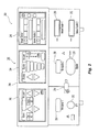
- the generator 200 includes a user interface 241 having one or more display screens 242, 244, 246 for providing the user with variety of output information (e.g., intensity settings, treatment complete indicators, etc.). Each of the screens 242, 244, 246 is associated with corresponding connector 250, 252, 254, 256, 258, 260, and 262.
- the generator 200 includes suitable input controls (e.g., buttons, activators, switches, touch screen, etc.) for controlling the generator 200.
- the display screens 242, 244, 246 are also configured as touch screens that display a corresponding menu for the electrosurgical instruments (e.g., plasma instrument 12, etc.). The user then adjusts inputs by simply touching corresponding menu options.
- Screen 242 controls monopolar output and the devices connected to the connectors 250 and 252.
- Connector 250 is configured to couple to a monopolar electrosurgical instrument (e.g., electrosurgical pencil) and connector 252 is configured to couple to a foot switch (not shown). The foot switch provides for additional inputs (e.g., replicating inputs of the generator 200).
- Screen 244 controls monopolar, plasma and bipolar output and the devices connected to the connectors 256 and 258.
- Connector 256 is configured to couple to other monopolar instruments.
- Connector 258 is configured to couple to plasma instrument 12.
- Connector 254 may be used to connect to one or more return electrode pads 6.
- the return electrode pad 6 is coupled to the generator 200 via the return pad cable 8, which is coupled to the connector 254 via a plug (not shown).
- the return electrode pad 6 is coupled to a polarization controller 170, which is in turn coupled to the connector 254 (as shown in Fig. 7 ), which is described in further detail below.
- Screen 246 controls plasma procedures performed by the plasma instrument 12 that may be plugged into the connectors 260 and 262.
- Fig. 3 shows a schematic block diagram of the generator 200 configured to output electrosurgical energy.
- the generator 200 includes a controller 224, a power supply 227, and a radio-frequency (RF) amplifier 228.
- the power supply 227 may be a high voltage, DC power supply connected to an AC source (e.g., line voltage) and provides high voltage, DC power to the RF amplifier 228 via leads 227a and 227b, which then converts high voltage, DC power into treatment energy (e.g., electrosurgical or microwave) and delivers the energy to the active terminal 230.
- treatment energy e.g., electrosurgical or microwave
- the energy is returned thereto via the return terminal 232.
- the active and return terminals 230 and 232 and coupled to the RF amplifier 228 through an isolation transformer 229.
- the RF amplifier 228 is configured to operate in a plurality of modes, during which the generator 200 outputs corresponding waveforms having specific duty cycles, peak voltages, crest factors, etc. It is envisioned that in other embodiments, the generator 200 may be based on other types of suitable power supply topologies.
- the controller 224 includes a processor 225 operably connected to a memory 226, which may include transitory type memory (e.g., RAM) and/or non-transitory type memory (e.g., flash media, disk media, etc.).
- the processor 225 includes an output port that is operably connected to the power supply 227 and/or RF amplifier 228 allowing the processor 225 to control the output of the generator 200 according to either open and/or closed control loop schemes.
- a closed loop control scheme is a feedback control loop, in which a plurality of sensors measure a variety of tissue and energy properties (e.g., tissue impedance, tissue temperature, output power, current and/or voltage, etc.), and provide feedback to the controller 224.
- the controller 224 then signals the power supply 227 and/or RF amplifier 228, which adjusts the DC and/or power supply, respectively.
- the processor 225 may be substituted by using any logic processor (e.g., control circuit) adapted to perform the calculations and/or set of instructions described herein including, but not limited to, field programmable gate array, digital signal processor, and combinations thereof.
- the generator 200 includes a plurality of sensors 280, e.g., an RF current sensor 280a, and an RF voltage sensor 280b.
- Various components of the generator 200 namely, the RF amplifier 228, the RF current and voltage sensors 280a and 280b, may be disposed on a printed circuit board (PCB).
- the RF current sensor 280a is coupled to the active terminal 230 and provides measurements of the RF current supplied by the RF amplifier 228.
- the RF current sensor 280a may be coupled to the return terminal 232.
- the RF voltage sensor 280b is coupled to the active and return terminals 230 and 232 provides measurements of the RF voltage supplied by the RF amplifier 228.
- the RF current and voltage sensors 280a and 280b may be coupled to active and return leads 228a and 228b, which interconnect the active and return terminals 230 and 232 to the RF amplifier 228, respectively.
- the RF current and voltage sensors 280a and 280b provide the sensed RF voltage and current signals, respectively, to the controller 224, which then may adjust output of the power supply 227 and/or the RF amplifier 228 in response to the sensed RF voltage and current signals.
- the controller 224 also receives input signals from the input controls of the generator 200 and/or the plasma instrument 12. The controller 224 utilizes the input signals to adjust the power output of the generator 200 and/or performs other control functions thereon.
- the system 10 provides a flow of plasma through the instrument 12 to a workpiece (e.g., tissue).
- Plasma feedstocks which include ionizable media and optional precursor feedstocks, are supplied by the ionizable media source 16 to the plasma instrument 12.
- the ionizable media source 16 may include various flow sensors and controllers (e.g., valves, mass flow controllers, etc.) to control the flow of ionizable media to the instrument 12.
- the ionizable media and/or the precursor feedstock are provided to the plasma instrument 12 where the plasma feedstocks are ignited to form plasma effluent containing ions, radicals, photons from the specific excited species and metastables that carry internal energy to drive desired chemical reactions in the workpiece or at the surface thereof.
- the feedstocks may be mixed upstream from the ignition point or midstream thereof (e.g., at the ignition point) of the plasma effluent.
- the ionizable media source 16 may include a storage tank, a pump, and/or flow meter (not explicitly shown).
- the ionizable media may be a liquid or a gas such as argon, helium, neon, krypton, xenon, radon, carbon dioxide, nitrogen, hydrogen, oxygen, etc. and their mixtures, and the like. These and other gases may be initially in a liquid form that is gasified during application.
- the precursor feedstock may be either in solid, gaseous or liquid form and may be mixed with the ionizable media in any state, such as solid, liquid (e.g., particulates or droplets), gas, and the combination thereof.
- the ionizable media source 16 may be coupled to the plasma instrument 12 via tubing 14.
- the tubing 14 may be fed from multiple sources of ionizible media and/or precursor feedstocks, which may combined into unified tubing to deliver a mixture of the ionizable media and the precursor feedstock to the instrument 12 at a proximal end thereof. This allows for the plasma feedstocks, e.g., the precursor feedstock and the ionizable gas, to be delivered to the plasma instrument 12 simultaneously prior to ignition of the mixture therein.
- the ionizable media and precursor feedstocks may be supplied at separate connections, such that the mixing of the feedstocks occurs within the plasma instrument 12 upstream from the ignition point such that the plasma feedstocks are mixed proximally of the ignition point.
- the plasma feedstocks may be mixed midstream, e.g., at the ignition point or downstream of the plasma effluent, directly into the plasma.
- the ionizable media may be supplied to the instrument 12 proximally of the ignition point, while the precursor feedstocks are mixed therewith at the ignition point.
- the ionizable media may be ignited in an unmixed state and the precursors may be mixed directly into the ignited plasma.
- the plasma feedstocks Prior to mixing, the plasma feedstocks may be ignited individually.
- the plasma feedstock may be supplied at a predetermined pressure to create a flow of the medium through the instrument 12, which aids in the reaction of the plasma feedstocks and produces a plasma effluent.
- the plasma according to the present disclosure may be generated at or near atmospheric pressure under normal atmospheric conditions.
- the precursors may be any chemical species capable of forming reactive species such as ions, electrons, excited-state (e.g., metastable) species, molecular fragments (e.g., radicals) and the like, when ignited by electrical energy from the Generator 200 or when undergoing collisions with particles (electrons, photons, or other energy-bearing species of limited and selective chemical reactivity) formed from ionizable media 16.
- reactive species such as ions, electrons, excited-state (e.g., metastable) species, molecular fragments (e.g., radicals) and the like, when ignited by electrical energy from the Generator 200 or when undergoing collisions with particles (electrons, photons, or other energy-bearing species of limited and selective chemical reactivity) formed from ionizable media 16.
- the precursors may include various reactive functional groups, such as acyl halide, alcohol, aldehyde, alkane, alkene, amide, amine, butyl, carboxlic, cyanate, isocyanate, ester, ether, ethyl, halide, haloalkane, hydroxyl, ketone, methyl, nitrate, nitro, nitrile, nitrite, nitroso, peroxide, hydroperoxide, oxygen, hydrogen, nitrogen, and combination thereof.
- reactive functional groups such as acyl halide, alcohol, aldehyde, alkane, alkene, amide, amine, butyl, carboxlic, cyanate, isocyanate, ester, ether, ethyl, halide, haloalkane, hydroxyl, ketone, methyl, nitrate, nitro, nitrile, nitrite, nitroso, peroxide, hydroperoxide, oxygen
- the precursor feedstocks may be water, halogenoalkanes, such as dichloromethane, tricholoromethane, carbon tetrachloride, difluoromethane, trifluoromethane, carbon tetrafluoride, and the like; peroxides, such as hydrogen peroxide, acetone peroxide, benzoyl peroxide, and the like; alcohols, such as methanol, ethanol, isopropanol, ethylene glycol, propylene glycol, alkalines such as NaOH, KOH, amines, alkyls, alkenes, and the like.
- halogenoalkanes such as dichloromethane, tricholoromethane, carbon tetrachloride, difluoromethane, trifluoromethane, carbon tetrafluoride, and the like
- peroxides such as hydrogen peroxide, acetone peroxide, benzoyl peroxide, and the like
- the instrument 12 includes a handle housing 100 having a proximal end 102 and a distal end 104.
- the housing 100 also includes a lumen 106 defined therein having a proximal end coupled to the gas tubing 14 from the ionizable media source 16 and a distal end terminating at the distal end 104 of the housing 100.
- the instrument 12 also includes an elongated body 120 having a shaft housing 122 defining a lumen 124 therethrough as shown in Fig. 4B .
- the shaft housing 122 may be rigid or flexible.
- the lumens 106 and 124 are in gaseous and/or fluid communication with the ionizable media source 16 allowing for the flow of ionizable media and precursor feedstocks to flow through the lumens 106 and 124.
- conductors 4a, 4b are coupled to the electrodes 108 and 110, respectively.
- the conductors 4a, 4b extend through the housing 100 and shaft housing 122 of the elongated body 120 and are connected to the generator 200 via the cable 4.
- the cable 4 may include a plug (not shown) connecting the instrument 12 to the generator 200 at the connector 258.
- Each of the electrodes 108 and 110 is connected to the generator 200 and may therefore be energized by the generator 200 allowing the instrument 12 to operate in non-polarized manner as described in further detail below.
- the conductor 4a is coupled to the proximal end of the electrode 108.
- the conductor 4b may be a lead or a wire embedded in the shaft housing 122 and is coupled to the electrode 110 by exposing a distal portion of the conductor 4b as shown in Fig. 4B .
- the shaft housing 122 may have a diameter from about 2 mm to about 20 mm allowing the instrument 12 to be inserted through operating ports of an endoscope or access ports in laparoscopic procedures as well as natural body orifices for application of the plasma effluent at the operating site during minimally invasive procedures.
- the shaft housing 122 may be formed from any suitable dielectric material including thermoplastics, such as acrylics, celluloid, cellulose acetate, cyclic olefin copolymer, ethylene-vinyl acetate, fluoropolymers (e.g., polytetrafluoroethylene), ionomers, polyoxymethylene, polyacrylates, polyacrylonitrile, polyamide, polyamide-imide, polyaryletherketon, polybutadiene, polybutylene, polybutylene terephthalate, polycaprolactone, polychlorotrifluoroethylene, polyethylene terephthalate, polycyclohexylene dimethylene terephthalate, polycarbonate, polyhydroxyalkanoates, polyketones, polyester, polyethylene, polyetheretherketone, polyetherketoneketone, polyetherimide, polyethersulfone, chlorinated polyethylene, polyimide, polylactic acid, polymethylpentene, polyphenylene oxide, polyphenylene sul
- the instrument 12 further includes an applicator tip 130 coupled to the elongated body 120 at the distal end thereof.
- the applicator tip 130 is inserted into the distal end of the lumen 124.
- the tip 130 may be formed from any suitable dielectric materials including the thermoplastic materials described above if the temperature of the plasma is sufficiently low or any other suitable heat-resistant dielectric material, including ceramic materials. Suitable ceramic materials include, but are not limited to, metal oxide ceramics, non-oxide ceramics, ceramic composites, and combinations thereof.
- Suitable oxide ceramics include zirconium oxide, aluminum oxide, silica oxide, magnesium oxide, iron oxide, calcium oxide, yttrinum oxide, cerium oxide, alumina oxide, silicon oxide, calcium silicate, copper oxide, nickel oxide, praseodymium oxide, titanium oxide, erbium oxide, europium oxide, holmium oxide, chromium oxide, manganese oxide, vanadium oxide, cobalt oxide, neodymium oxide and combinations and composites thereof such as fiber composites, metal oxide composites, non-oxide composites, alumina/zirconia composites, and the like.
- the applicator tip 130 includes a proximal portion 132 configured and dimensioned to be inserted into the distal end of the lumen 124.
- the applicator tip 130 also includes a distal portion 134 disposed outside the lumen 124.
- the distal portion 134 may have a larger diameter than that of the lumen 124 such that the distal portion 134 has a cross-section that is substantially similar to or larger than the cross-section of the shaft housing 122 to protect the shaft housing 122 from the plasma generated at the applicator tip 130.
- the applicator tip 130 also includes a lumen 136 defined therethrough that is fluid communication with the lumen 124.
- the lumen 136 may have any suitable shape for tailoring the size and/or shape of the plasma plume generated by the instrument 12.
- the lumen 124 may also include one or more surfaces for further shaping (e.g., narrowing) the plasma plume prior to exiting the instrument 12.
- the instrument 12 also includes two or more electrodes 108, 110 disposed within the applicator tip 130, shown as an inner and outer electrodes, respectively.
- the electrodes 108 and 110 may be formed from a conductive material including metals, such as stainless steel, copper, aluminium, tungsten, and combinations and alloys thereof.
- the electrodes 108 and 110 may have any suitable shape for conducting electrical energy and igniting the ionizable media including, but not limited to, rings, strips, needles, meshes, and the like.
- the electrodes 108 and 110 may also be disposed outside or within the lumen 124 for capacitive coupling with the ionizable media as described in further detail below.
- the ionizable media in conjunction with the optional precursor feedstocks is ignited by application of energy through the electrodes 108 and 110 to form a plasma plume exiting through an opening 115 of the applicator tip 130.
- the electrode 108 may be configured as an inner electrode as shown in Fig. 4B .
- the electrode 108 may be enclosed in an insulative layer 108a and may be supported within the lumen using a spacer 113.
- the electrode 110 is disposed on the proximal portion 132 of the applicator tip 130.
- the electrode 110 may include one or more electrodes that are insulated from the electrode 108 by the dielectric material of the applicator tip 130 allowing for capacitive coupling between the electrodes 108 and 110.
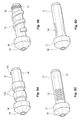
- the electrode 110 may include one or more concentric rings 110a as shown in Fig. 5A , a spiral 110b as shown in Fig. 5B , a plurality of interconnected strips 110c as shown in Fig. 5C , one or more plates 110d as shown in Fig. 5D .
- Fig. 5E shows another embodiment of one or more electrodes 110e having a substantially ring-like shape.
- the electrode 110e includes a raised surface 111a having a proximal and distal concave edges 111b, 111c.
- the concave shape of the edges 111b, 111c provides for a sharp transition between the edges 111b, 111c and the surface 111a. This transition provides for concentration of the electrical field generated between the electrodes 108 and 110e resulting in higher transfer of energy to the plasma.
- the electrodes 110a-110e may be formed from any suitable conductive material (e.g., metals) using machining, forging, metal injection molding, and other suitable methods. The electrodes 110a-110e may then be bonded to the surface of the applicator tip 130 using adhesives or any other suitable methods.
- suitable conductive material e.g., metals
- the electrodes 110a-110e may be formed from conductive particles using various methods including, but not limited to, plasma deposition, atomic layer deposition, screen printing, spraying, painting and combinations thereof.
- the conductive particles may be applied to any desired structure for forming the electrode, e.g., ring-like structure of the electrode 110e including the raised surface 111a and concave edges 111b, 111c.
- the electrode structure may be formed from a dielectric material, e.g., the applicator tip 130.
- inks including a plurality of conductive particles suspended in a solvent may be used to form the electrodes 110a-110e. After application, the solvent in the ink evaporates following application on the surface of the applicator tip 130 leaving behind a layer of conductive particles thereby forming the electrodes 110a-110e.
- the applicator tip 130 may be removably coupled to the elongated body 120 using any suitable mechanical interconnection including, but not limited to frictional-type mount, a bayonet mount using one or more bayonet lugs 115 as shown in Fig. 5A , a thread mount using a threadable connection 117 as shown in Fig. 5B , and combinations thereof.
- the distal portion of the lumen 124 includes a corresponding connection, such as one or more slits for interfacing with the bayonet lugs 115, a threadable connection, and the like.
- Removable applicator tips 130 allows for interchangeability and selection of the suitable applicator tip 130 for the application.
- Applicator tips 130 may have various electrode designs as described above with respect to Figs. 5A-5E , differently shaped lumen 136 for tailoring the size and/or shape of the plasma plume generated by the instrument 12.
- the applicator tips 130 may also be formed from different dielectric materials to tailor coupling between the electrodes 108, 110.
- Applicator tip 130 maybe a reusable component used to extend the life of instrument 12 in long procedures or across multiple procedures. Thus, a method of exchanging the applicator tips 130 is an important aspect in current market trends where remanufacture of instruments reduces consumer cost.
- the applicator tip 130 may include an identifier 119 as shown in Fig. 5C configured to store one or more values corresponding to properties of the applicator tip 130.
- the identifier 119 may be RFID, EEPROM or any other suitable storage medium accessible by the generator 200. Values stored in the identifier 119 may include, but are not limited to, electrode type/structure, dielectric material of the applicator tip 130, shape/structure of the lumen 136, serial number, and the like.
- the storage medium (e.g., non-transitory) identifier 119 may be wholly or partially rewritable and may store usage data including sterilization counts, usage counts, time used and the like.
- the generator 200 may include a corresponding reader/writer configured to interface with the identifier 119.
- the generator 200 may tailor its output based on the data stored in the identifier 119 as well as update the identifier 119 to reflect usage/sterilization data after the instrument 12 is used.
- the instrument 12 also includes an electrically conductive sheath 140 disposed between the shaft housing 122 and an inner insulative sheath 142, which defines the lumen 124.
- the conductive sheath 140 is coupled to the conductor 4b and extends up to the proximal end of the shaft housing 122 such that when the proximal portion 132 of the applicator tip 130 is inserted, the electrodes 110 (e.g., electrodes 110e) are in contact with the conductive sheath 140.
- the insulative sheath 142 extends only up to the proximal portion 132 of the applicator tip 130, namely, the proximal end of the electrode 110, thus fully insulating the ionizable media within the lumen 124 from the electrodes 108, 110 until the applicator tip 130.
- Figs. 6A-6B show another embodiment of the instrument 12 in which the shaft housing 122 is flexible and is configured for passive or controlled deflection.
- a pull-wire 107 or another suitable actuation mechanism extends from the handle housing 100 at the proximal end of the shaft housing 122.
- the pull-wire 107 is movable from a first generally relaxed position wherein the proximal and distal portions of the shaft housing 122 are substantially aligned with a longitudinal axis defined by the shaft to a second retracted or tensed position wherein the distal portion flexes (e.g., deflects) from the longitudinal axis at a desired angle.
- the pull-wire 107 may be coupled to any suitable actuation mechanism, such as a trigger-actuated tensioning mechanism (not shown).
- the conductor 4b may be configured as the pull-wire 107 and/or may be coupled to the pull-wire 107 allowing the pull-wire 107 to act as the conductor for the electrode 110.
- the instrument 12 also includes one or more activation switches 150a, 150b, 150c, each of which extends through top-half shell portion of housing 100.
- Each activation switch 150a, 150b, 150c is operatively supported on a respective tactile element (e.g., a snap-dome switch) provided on a switch plate 154.
- Each activation switch 150a, 150b, 150c controls the transmission of electrical energy supplied from generator 200 to the electrodes 108 and 110.
- the activation switches 150a-150c transmit control signals via a voltage divider network (VDN) or other circuit control means through control leads within the cable 4 to the generator 200.
- VDN voltage divider network
- the term "voltage divider network” relates to any known form of resistive, capacitive or inductive switch closure (or the like) which determines the output voltage across a voltage source (e.g., one of two impedances) connected in series.
- a “voltage divider” as used herein relates to a number of resistors connected in series, which are provided with taps at certain points to make available a fixed or variable fraction of the applied voltage.
- the instrument 12 further includes a slide switch 158 slidingly supported on or within housing 100 in a guide channel 160 defined therein.
- the switch 158 may be configured to function as a slide potentiometer, sliding over and along VDN.
- the switch 158 has a first position at a proximal-most position (e.g., closest to cable 4) corresponding to 0 % or a relatively low polarization setting, a second position wherein the switch 158 is at a distal-most position corresponding to 100 % or a relatively high polarization setting.
- the switch 158 may be disposed in a plurality of intermediate positions wherein the switch 158 is at positions between the distal-most position and the proximal-most position corresponding to various intermediate polarization settings. As can be appreciated, the polarization settings from the proximal end to the distal end may be reversed, e.g., high to low.
- Activation switches 150a-150c and the switch 158 are described in further detail in a commonly-owned U.S. Patent No. 7,879,033 , the entire contents of which are incorporated by reference herein.
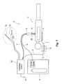
- Fig. 7 shows the system 10 for applying plasma to a patient "P.”
- the return electrode pad 6 is coupled to the patient.
- the return electrode pad 6 may be disposed underneath the patient “P” such that the patient “P” rests on top thereof.
- the return electrode pad 6 may be coupled to the patient “P” with conductive hydrogels and/or adhesives.
- the system 10 may also include monopolar and bipolar surgical instruments 11a, 11b, respectively, which may be energized by the generator 200 to treat tissue.
- the return electrode pad 6 is coupled to the polarization controller 170, which is in turn coupled to the connector 254 ( Fig. 2 ) of the generator 200 via the cable 8.
- two or more return electrode pads 6 may be coupled to the patient "P.”
- a splitter (not shown) may be used to couple multiple return electrode pads 6 to the generator 200 (e.g., at the connector 254). The splitter may be coupled to the polarization controller 170 prior to being connected to the generator 200.
- multiple polarization controllers 170 may be utilized to accommodate a plurality of return electrode pads 6.
- the polarization controller 170 may be disposed within the generator 200 and be coupled to the input of the return electrode pad 6 at the generator 200 (e.g., connector 254).
- the polarization controller 170 includes a variable resistance 172, which may be adjusted to control the conductive coupling of the return electrode pad 6 to the generator 200.
- the instrument 12 may be operated in polarized, non-polarized, or hybrid manner.
- the variable resistance 172 being fully activated such that the return electrode pad 6 is not coupled to the generator 200
- the instrument 2 operates in a non-polarized manner, with the electrodes 108, 110 being only coupled to the generator 200 and therefore, being energized.
- the variable resistance 172 being fully deactivated such that the return electrode pad 6 is fully-coupled to the generator 200.
- the electrodes 108, 110 of the instrument 12 in combination with the return electrode pad 6 are connected to the generator 200 allowing for the operation of the system 10 in polarized manner.
- Variable resistance 172 may include a plurality of resistors having a predetermined resistance that may be switched in and out of the circuit using switching elements (e.g., relays, transistors, field effect transistors, etc.).
- the variable resistance 172 may also include a variable potentiometer controllable by an electromechanical actuator.
- the variable resistance 172 may include voltage-controlled resistances such as one or more transistors operated in its linear region or other semiconductor-based, electrically-controlled variable resistances, such as PIN diodes.
- the variable resistance 172 may be adjusted in fixed increments or may be infinitely variable (e.g., limited by electrical/physical limitations of its constituent components) or combinations thereof.
- Switching resistance in variable manner allows for fine-tuning the polarization of the system 10 to achieve a desired electrosurgical effect (e.g., maintaining constant current or constant voltage through the return electrode pad 6 or the instrument 12).
- Switching the resistance in a fixed manner e.g., switching between fully-connected or fully-disconnected
- variable resistance 172 allows for switching between non-polarized or polarized configurations, respectively.
- Resistance of the polarization controller 170 may be controlled either through the generator 200 and/or the instrument 12.
- the screen 244 may be a touchscreen that allows for control of the outputs the connectors 256 and 258 as well as the resistance of the polarization controller 170.
- the screen 244 may be replaced and/or supplemented by other controls (e.g., keyboard, buttons, etc.).
- the screen 244 includes input buttons for adjusting the degree of polarization. This may be accomplished by a variety of control schemes, shown on the screen 244 as graphical user interface elements, such as a slidable bar, predefined increment buttons, text and/or number inputs, and combinations thereof.
- the polarization settings may be displayed as a percentage or any other suitable scale for conveying the degree of polarization.
- the polarization settings are used by the generator 200 to adjust the resistance of the polarization controller 170, namely, the variable resistance 172 as described above to achieve a desired degree of polarization of the plasma outputted by the instrument 12.
- the instrument 12 may also control various properties of the plasma beam.
- the activation switches 150a-150c may be used to activate the generator 200 and/or to control the flow of ionizable media from the ionizable media source 16.
- the slide switch 158 is configured to adjust the resistance of the polarization controller 170, namely, the variable resistance 172 as described above to achieve a desired degree of polarization of the plasma outputted by the instrument 12.
- additional input devices may be used such as foot switches or handheld keyboards and/or remotes.
- the input devices e.g., activation switches 150a-150c
- the input devices may be two-stage switches where upon activation of the first stage, ionizable media and RF energy are supplied to the instrument 12 at a sufficient level to prime the active plasma field within the lumen 106 to initiate non-therapeutic ionization. This enables the user to visualize the target tissue relative to the non-therapeutic ionized gas plume.
- the generator 200 may include a feedback control loop to ensure the pre-ionization level is achieved and maintained at minimum needed RF power.
- a single wave spike may be generated to maintain sufficient ionized field without over heating the plasma instrument by minimizing RMS power delivered to pre-ionization field.
- trace amounts of substantially non-electronegative compositions may be added to improve visibility of the ionized gas. Suitable tracer compositions include compounds such as sodium, neon, xenon, combinations thereof, and the like.
- the closure of the second stage of the switch increases RF power to therapeutic levels and simultaneously increases conductivity through the return electrode pad 6 thereby initiating targeted therapeutic results.
- activation of the second stage would decrease the resistivity of the variable resistance 172 as described above.
- the present disclosure provides for a plasma electrosurgical system with variable polarization, which allows for real-time adjustment of the plasma beam, thereby allowing for achieving specific surgical effects.
- the system also allows for used of standard electrosurgical generators (e.g., non-resonance matching generators operating in the radio frequency range at about 400 kHz) as a power source for exciting the plasma.
- standard electrosurgical generators e.g., non-resonance matching generators operating in the radio frequency range at about 400 kHz
- a single electrosurgical generator may be used for generating plasma as well as operating with conventional electrosurgical instruments (e.g., monopolar, bipolar, etc.), thereby reducing the cost of operating room equipment.
Landscapes
- Health & Medical Sciences (AREA)
- Surgery (AREA)
- Engineering & Computer Science (AREA)
- Life Sciences & Earth Sciences (AREA)
- Biomedical Technology (AREA)
- Molecular Biology (AREA)
- Nuclear Medicine, Radiotherapy & Molecular Imaging (AREA)
- Plasma & Fusion (AREA)
- Physics & Mathematics (AREA)
- Heart & Thoracic Surgery (AREA)
- Medical Informatics (AREA)
- Otolaryngology (AREA)
- Animal Behavior & Ethology (AREA)
- General Health & Medical Sciences (AREA)
- Public Health (AREA)
- Veterinary Medicine (AREA)
- Surgical Instruments (AREA)
- Plasma Technology (AREA)
Applications Claiming Priority (2)
| Application Number | Priority Date | Filing Date | Title |
|---|---|---|---|
| US201361789168P | 2013-03-15 | 2013-03-15 | |
| US14/171,018 US20140276717A1 (en) | 2013-03-15 | 2014-02-03 | Bipolar gas plasma coagulation nozzle |
Publications (2)
| Publication Number | Publication Date |
|---|---|
| EP2777580A2 true EP2777580A2 (de) | 2014-09-17 |
| EP2777580A3 EP2777580A3 (de) | 2014-11-05 |
Family
ID=50236002
Family Applications (1)
| Application Number | Title | Priority Date | Filing Date |
|---|---|---|---|
| EP14158043.1A Withdrawn EP2777580A3 (de) | 2013-03-15 | 2014-03-06 | Bipolare Gasplasmakoagulationsdüse |
Country Status (2)
| Country | Link |
|---|---|
| US (1) | US20140276717A1 (de) |
| EP (1) | EP2777580A3 (de) |
Cited By (2)
| Publication number | Priority date | Publication date | Assignee | Title |
|---|---|---|---|---|
| EP3292830A1 (de) * | 2016-08-02 | 2018-03-14 | Covidien LP | System und verfahren zur katheterbasierten plasmakoagulation |
| WO2018175320A3 (en) * | 2017-03-20 | 2018-11-08 | Nanova, Inc. | Device for generating and delivering low temperature plasma |
Families Citing this family (12)
| Publication number | Priority date | Publication date | Assignee | Title |
|---|---|---|---|---|
| US10166061B2 (en) * | 2014-03-17 | 2019-01-01 | Intuitive Surgical Operations, Inc. | Teleoperated surgical system equipment with user interface |
| USD734469S1 (en) * | 2014-03-27 | 2015-07-14 | Covidien Lp | Handle for medical treatment device |
| USD736919S1 (en) * | 2014-05-06 | 2015-08-18 | Benvenue Medical, Inc. | Handle for a medical delivery device |
| US10792086B2 (en) * | 2014-11-06 | 2020-10-06 | Covidien Lp | Cautery apparatus |
| US10278759B2 (en) * | 2014-11-06 | 2019-05-07 | Covidien Lp | Cautery apparatus |
| US20160235462A1 (en) * | 2015-02-12 | 2016-08-18 | U.S. Patent Innovations Llc | System and Method for Plasma Sealing of Tissue |
| EP3383304B1 (de) * | 2015-12-01 | 2021-12-01 | Trivedi, Amit | Kauterisierungsvorrichtung |
| US10245096B2 (en) | 2016-05-25 | 2019-04-02 | Covidien Lp | Pressure relief system for use with gas-assisted minimally invasive surgical devices |
| US10941058B2 (en) * | 2016-09-23 | 2021-03-09 | Jason D Lalli | Electrocoagulation system and method using plasma discharge |
| US20240216035A1 (en) * | 2021-05-20 | 2024-07-04 | Clear Intradermal Technologies, Inc. | Needle Adaptor for Plasma Generating Handpiece |
| US20240366291A1 (en) | 2023-01-20 | 2024-11-07 | Panacea Spine, LLC | Pain treatment using wanding of percutaneous surgical probe over sensory nerve |
| US20240245447A1 (en) | 2023-01-20 | 2024-07-25 | Panacea Spine, LLC | Electrocautery rhizotomy using wanding of energized electrocautery probe |
Citations (1)
| Publication number | Priority date | Publication date | Assignee | Title |
|---|---|---|---|---|
| US7879033B2 (en) | 2003-11-20 | 2011-02-01 | Covidien Ag | Electrosurgical pencil with advanced ES controls |
Family Cites Families (12)
| Publication number | Priority date | Publication date | Assignee | Title |
|---|---|---|---|---|
| DE3670022D1 (de) * | 1986-08-11 | 1990-05-10 | Mo Med Inst Pirogova | Vorrichtung zum schneiden von biologischen geweben mit plasmaboegen. |
| US5024617A (en) * | 1989-03-03 | 1991-06-18 | Wilson-Cook Medical, Inc. | Sphincterotomy method and device having controlled bending and orientation |
| US5403311A (en) * | 1993-03-29 | 1995-04-04 | Boston Scientific Corporation | Electro-coagulation and ablation and other electrotherapeutic treatments of body tissue |
| US6475217B1 (en) * | 1999-10-05 | 2002-11-05 | Sherwood Services Ag | Articulating ionizable gas coagulator |
| US6475215B1 (en) * | 2000-10-12 | 2002-11-05 | Naim Erturk Tanrisever | Quantum energy surgical device and method |
| JP2002301088A (ja) * | 2001-04-05 | 2002-10-15 | Olympus Optical Co Ltd | 内視鏡用治療装置 |
| US8048101B2 (en) * | 2004-02-25 | 2011-11-01 | Femasys Inc. | Methods and devices for conduit occlusion |
| US20070106288A1 (en) * | 2005-11-09 | 2007-05-10 | Arthrocare Corporation | Electrosurgical apparatus with fluid flow regulator |
| WO2009146432A1 (en) * | 2008-05-30 | 2009-12-03 | Colorado State University Research Foundation | Plasma-based chemical source device and method of use thereof |
| US20100204690A1 (en) * | 2008-08-13 | 2010-08-12 | Arthrocare Corporation | Single aperture electrode assembly |
| KR101044314B1 (ko) * | 2008-11-25 | 2011-06-29 | 포항공과대학교 산학협력단 | 저온 플라즈마를 이용한 지혈장치 |
| US20130261536A1 (en) * | 2012-03-27 | 2013-10-03 | Tyco Healthcare Group Lp | System and Method for Cholecystectomy |
-
2014
- 2014-02-03 US US14/171,018 patent/US20140276717A1/en not_active Abandoned
- 2014-03-06 EP EP14158043.1A patent/EP2777580A3/de not_active Withdrawn
Patent Citations (1)
| Publication number | Priority date | Publication date | Assignee | Title |
|---|---|---|---|---|
| US7879033B2 (en) | 2003-11-20 | 2011-02-01 | Covidien Ag | Electrosurgical pencil with advanced ES controls |
Cited By (5)
| Publication number | Priority date | Publication date | Assignee | Title |
|---|---|---|---|---|
| EP3292830A1 (de) * | 2016-08-02 | 2018-03-14 | Covidien LP | System und verfahren zur katheterbasierten plasmakoagulation |
| US10524849B2 (en) | 2016-08-02 | 2020-01-07 | Covidien Lp | System and method for catheter-based plasma coagulation |
| US11376058B2 (en) | 2016-08-02 | 2022-07-05 | Covidien Lp | System and method for catheter-based plasma coagulation |
| WO2018175320A3 (en) * | 2017-03-20 | 2018-11-08 | Nanova, Inc. | Device for generating and delivering low temperature plasma |
| US10631396B2 (en) | 2017-03-20 | 2020-04-21 | Nanova, Inc. | Device for generating and delivering low temperature plasma |
Also Published As
| Publication number | Publication date |
|---|---|
| US20140276717A1 (en) | 2014-09-18 |
| EP2777580A3 (de) | 2014-11-05 |
Similar Documents
| Publication | Publication Date | Title |
|---|---|---|
| EP2777580A2 (de) | Bipolare Gasplasmakoagulationsdüse | |
| US10750605B2 (en) | Variable frequency excitation plasma device for thermal and non-thermal tissue effects | |
| US10898255B2 (en) | Bipolar plasma catheter | |
| EP2789305B1 (de) | Multimodale elektrochirurgische Vorrichtung | |
| CN108697464B (zh) | 具有多种治疗方式的电外科器械 | |
| US11376058B2 (en) | System and method for catheter-based plasma coagulation | |
| EP2765838B1 (de) | System und Verfahren zur Kontrolle eines hybriden polarisierten/nichtpolarisierten Plasmastrahls | |
| US20200138504A1 (en) | System and method for sinus surgery | |
| WO2017106602A1 (en) | Electrosurgical device with multiple monopolar electrode assembly | |
| US20130261536A1 (en) | System and Method for Cholecystectomy | |
| EP3383290B1 (de) | Mischen von kaltplasmastrahlen mit atmosphäre | |
| RU2195226C2 (ru) | Способ высокочастотного электрохирургического воздействия на биологические ткани |
Legal Events
| Date | Code | Title | Description |
|---|---|---|---|
| 17P | Request for examination filed |
Effective date: 20140306 |
|
| AK | Designated contracting states |
Kind code of ref document: A2 Designated state(s): AL AT BE BG CH CY CZ DE DK EE ES FI FR GB GR HR HU IE IS IT LI LT LU LV MC MK MT NL NO PL PT RO RS SE SI SK SM TR |
|
| AX | Request for extension of the european patent |
Extension state: BA ME |
|
| PUAI | Public reference made under article 153(3) epc to a published international application that has entered the european phase |
Free format text: ORIGINAL CODE: 0009012 |
|
| PUAL | Search report despatched |
Free format text: ORIGINAL CODE: 0009013 |
|
| AK | Designated contracting states |
Kind code of ref document: A3 Designated state(s): AL AT BE BG CH CY CZ DE DK EE ES FI FR GB GR HR HU IE IS IT LI LT LU LV MC MK MT NL NO PL PT RO RS SE SI SK SM TR |
|
| AX | Request for extension of the european patent |
Extension state: BA ME |
|
| RIC1 | Information provided on ipc code assigned before grant |
Ipc: A61B 18/12 20060101AFI20141001BHEP |
|
| R17P | Request for examination filed (corrected) |
Effective date: 20150427 |
|
| RBV | Designated contracting states (corrected) |
Designated state(s): AL AT BE BG CH CY CZ DE DK EE ES FI FR GB GR HR HU IE IS IT LI LT LU LV MC MK MT NL NO PL PT RO RS SE SI SK SM TR |
|
| 17Q | First examination report despatched |
Effective date: 20171002 |
|
| GRAP | Despatch of communication of intention to grant a patent |
Free format text: ORIGINAL CODE: EPIDOSNIGR1 |
|
| INTG | Intention to grant announced |
Effective date: 20200506 |
|
| STAA | Information on the status of an ep patent application or granted ep patent |
Free format text: STATUS: THE APPLICATION IS DEEMED TO BE WITHDRAWN |
|
| 18D | Application deemed to be withdrawn |
Effective date: 20200917 |