EP2777608B1 - Système de prothèse endoluminale - Google Patents
Système de prothèse endoluminale Download PDFInfo
- Publication number
- EP2777608B1 EP2777608B1 EP14275047.0A EP14275047A EP2777608B1 EP 2777608 B1 EP2777608 B1 EP 2777608B1 EP 14275047 A EP14275047 A EP 14275047A EP 2777608 B1 EP2777608 B1 EP 2777608B1
- Authority
- EP
- European Patent Office
- Prior art keywords
- graft
- temporary channel
- prosthesis
- disposed
- channel
- Prior art date
- Legal status (The legal status is an assumption and is not a legal conclusion. Google has not performed a legal analysis and makes no representation as to the accuracy of the status listed.)
- Active
Links
Images


Classifications
-
- A—HUMAN NECESSITIES
- A61—MEDICAL OR VETERINARY SCIENCE; HYGIENE
- A61F—FILTERS IMPLANTABLE INTO BLOOD VESSELS; PROSTHESES; DEVICES PROVIDING PATENCY TO, OR PREVENTING COLLAPSING OF, TUBULAR STRUCTURES OF THE BODY, e.g. STENTS; ORTHOPAEDIC, NURSING OR CONTRACEPTIVE DEVICES; FOMENTATION; TREATMENT OR PROTECTION OF EYES OR EARS; BANDAGES, DRESSINGS OR ABSORBENT PADS; FIRST-AID KITS
- A61F2/00—Filters implantable into blood vessels; Prostheses, i.e. artificial substitutes or replacements for parts of the body; Appliances for connecting them with the body; Devices providing patency to, or preventing collapsing of, tubular structures of the body, e.g. stents
- A61F2/95—Instruments specially adapted for placement or removal of stents or stent-grafts
- A61F2/954—Instruments specially adapted for placement or removal of stents or stent-grafts for placing stents or stent-grafts in a bifurcation
-
- A—HUMAN NECESSITIES
- A61—MEDICAL OR VETERINARY SCIENCE; HYGIENE
- A61F—FILTERS IMPLANTABLE INTO BLOOD VESSELS; PROSTHESES; DEVICES PROVIDING PATENCY TO, OR PREVENTING COLLAPSING OF, TUBULAR STRUCTURES OF THE BODY, e.g. STENTS; ORTHOPAEDIC, NURSING OR CONTRACEPTIVE DEVICES; FOMENTATION; TREATMENT OR PROTECTION OF EYES OR EARS; BANDAGES, DRESSINGS OR ABSORBENT PADS; FIRST-AID KITS
- A61F2/00—Filters implantable into blood vessels; Prostheses, i.e. artificial substitutes or replacements for parts of the body; Appliances for connecting them with the body; Devices providing patency to, or preventing collapsing of, tubular structures of the body, e.g. stents
- A61F2/02—Prostheses implantable into the body
- A61F2/04—Hollow or tubular parts of organs, e.g. bladders, tracheae, bronchi or bile ducts
- A61F2/06—Blood vessels
- A61F2/07—Stent-grafts
-
- A—HUMAN NECESSITIES
- A61—MEDICAL OR VETERINARY SCIENCE; HYGIENE
- A61F—FILTERS IMPLANTABLE INTO BLOOD VESSELS; PROSTHESES; DEVICES PROVIDING PATENCY TO, OR PREVENTING COLLAPSING OF, TUBULAR STRUCTURES OF THE BODY, e.g. STENTS; ORTHOPAEDIC, NURSING OR CONTRACEPTIVE DEVICES; FOMENTATION; TREATMENT OR PROTECTION OF EYES OR EARS; BANDAGES, DRESSINGS OR ABSORBENT PADS; FIRST-AID KITS
- A61F2/00—Filters implantable into blood vessels; Prostheses, i.e. artificial substitutes or replacements for parts of the body; Appliances for connecting them with the body; Devices providing patency to, or preventing collapsing of, tubular structures of the body, e.g. stents
- A61F2/82—Devices providing patency to, or preventing collapsing of, tubular structures of the body, e.g. stents
- A61F2/856—Single tubular stent with a side portal passage
-
- A—HUMAN NECESSITIES
- A61—MEDICAL OR VETERINARY SCIENCE; HYGIENE
- A61F—FILTERS IMPLANTABLE INTO BLOOD VESSELS; PROSTHESES; DEVICES PROVIDING PATENCY TO, OR PREVENTING COLLAPSING OF, TUBULAR STRUCTURES OF THE BODY, e.g. STENTS; ORTHOPAEDIC, NURSING OR CONTRACEPTIVE DEVICES; FOMENTATION; TREATMENT OR PROTECTION OF EYES OR EARS; BANDAGES, DRESSINGS OR ABSORBENT PADS; FIRST-AID KITS
- A61F2/00—Filters implantable into blood vessels; Prostheses, i.e. artificial substitutes or replacements for parts of the body; Appliances for connecting them with the body; Devices providing patency to, or preventing collapsing of, tubular structures of the body, e.g. stents
- A61F2/02—Prostheses implantable into the body
- A61F2/24—Heart valves ; Vascular valves, e.g. venous valves; Heart implants, e.g. passive devices for improving the function of the native valve or the heart muscle; Transmyocardial revascularisation [TMR] devices; Valves implantable in the body
- A61F2/2412—Heart valves ; Vascular valves, e.g. venous valves; Heart implants, e.g. passive devices for improving the function of the native valve or the heart muscle; Transmyocardial revascularisation [TMR] devices; Valves implantable in the body with soft flexible valve members, e.g. tissue valves shaped like natural valves
- A61F2/2418—Scaffolds therefor, e.g. support stents
-
- A—HUMAN NECESSITIES
- A61—MEDICAL OR VETERINARY SCIENCE; HYGIENE
- A61F—FILTERS IMPLANTABLE INTO BLOOD VESSELS; PROSTHESES; DEVICES PROVIDING PATENCY TO, OR PREVENTING COLLAPSING OF, TUBULAR STRUCTURES OF THE BODY, e.g. STENTS; ORTHOPAEDIC, NURSING OR CONTRACEPTIVE DEVICES; FOMENTATION; TREATMENT OR PROTECTION OF EYES OR EARS; BANDAGES, DRESSINGS OR ABSORBENT PADS; FIRST-AID KITS
- A61F2/00—Filters implantable into blood vessels; Prostheses, i.e. artificial substitutes or replacements for parts of the body; Appliances for connecting them with the body; Devices providing patency to, or preventing collapsing of, tubular structures of the body, e.g. stents
- A61F2/82—Devices providing patency to, or preventing collapsing of, tubular structures of the body, e.g. stents
- A61F2/844—Devices providing patency to, or preventing collapsing of, tubular structures of the body, e.g. stents folded prior to deployment
-
- A—HUMAN NECESSITIES
- A61—MEDICAL OR VETERINARY SCIENCE; HYGIENE
- A61F—FILTERS IMPLANTABLE INTO BLOOD VESSELS; PROSTHESES; DEVICES PROVIDING PATENCY TO, OR PREVENTING COLLAPSING OF, TUBULAR STRUCTURES OF THE BODY, e.g. STENTS; ORTHOPAEDIC, NURSING OR CONTRACEPTIVE DEVICES; FOMENTATION; TREATMENT OR PROTECTION OF EYES OR EARS; BANDAGES, DRESSINGS OR ABSORBENT PADS; FIRST-AID KITS
- A61F2/00—Filters implantable into blood vessels; Prostheses, i.e. artificial substitutes or replacements for parts of the body; Appliances for connecting them with the body; Devices providing patency to, or preventing collapsing of, tubular structures of the body, e.g. stents
- A61F2/02—Prostheses implantable into the body
- A61F2/04—Hollow or tubular parts of organs, e.g. bladders, tracheae, bronchi or bile ducts
- A61F2/06—Blood vessels
- A61F2002/061—Blood vessels provided with means for allowing access to secondary lumens
-
- A—HUMAN NECESSITIES
- A61—MEDICAL OR VETERINARY SCIENCE; HYGIENE
- A61F—FILTERS IMPLANTABLE INTO BLOOD VESSELS; PROSTHESES; DEVICES PROVIDING PATENCY TO, OR PREVENTING COLLAPSING OF, TUBULAR STRUCTURES OF THE BODY, e.g. STENTS; ORTHOPAEDIC, NURSING OR CONTRACEPTIVE DEVICES; FOMENTATION; TREATMENT OR PROTECTION OF EYES OR EARS; BANDAGES, DRESSINGS OR ABSORBENT PADS; FIRST-AID KITS
- A61F2/00—Filters implantable into blood vessels; Prostheses, i.e. artificial substitutes or replacements for parts of the body; Appliances for connecting them with the body; Devices providing patency to, or preventing collapsing of, tubular structures of the body, e.g. stents
- A61F2/02—Prostheses implantable into the body
- A61F2/04—Hollow or tubular parts of organs, e.g. bladders, tracheae, bronchi or bile ducts
- A61F2/06—Blood vessels
- A61F2002/065—Y-shaped blood vessels
- A61F2002/067—Y-shaped blood vessels modular
-
- A—HUMAN NECESSITIES
- A61—MEDICAL OR VETERINARY SCIENCE; HYGIENE
- A61F—FILTERS IMPLANTABLE INTO BLOOD VESSELS; PROSTHESES; DEVICES PROVIDING PATENCY TO, OR PREVENTING COLLAPSING OF, TUBULAR STRUCTURES OF THE BODY, e.g. STENTS; ORTHOPAEDIC, NURSING OR CONTRACEPTIVE DEVICES; FOMENTATION; TREATMENT OR PROTECTION OF EYES OR EARS; BANDAGES, DRESSINGS OR ABSORBENT PADS; FIRST-AID KITS
- A61F2/00—Filters implantable into blood vessels; Prostheses, i.e. artificial substitutes or replacements for parts of the body; Appliances for connecting them with the body; Devices providing patency to, or preventing collapsing of, tubular structures of the body, e.g. stents
- A61F2/95—Instruments specially adapted for placement or removal of stents or stent-grafts
- A61F2002/9505—Instruments specially adapted for placement or removal of stents or stent-grafts having retaining means other than an outer sleeve, e.g. male-female connector between stent and instrument
- A61F2002/9511—Instruments specially adapted for placement or removal of stents or stent-grafts having retaining means other than an outer sleeve, e.g. male-female connector between stent and instrument the retaining means being filaments or wires
Definitions
- the present invention relates to an endoluminal prosthesis system and more particularly to a system for maintaining perfusion of branch vessels during an endovascular procedure.
- the aortic valve functions as a one-way valve between the heart and the rest of the body. Blood is pumped from the left ventricle of the heart, through the aortic valve, and into the aorta, which in turn supplies blood to the body. Between heart contractions the aortic valve closes, preventing blood from flowing backwards into the heart.
- Damage to the aortic valve can occur from a congenital defect, the natural aging process, and from infection or scarring. Over time, calcium may build up around the aortic valve causing the valve not to open and close properly. Certain types of damage may cause the valve to "leak,” resulting in “aortic insufficiency” or “aortic regurgitation.” Aortic regurgitation causes extra workload for the heart, and can ultimately result in weakening of the heart muscle and eventual heart failure.
- aortic valve After the aortic valve becomes sufficiently damaged, the valve may need to be replaced to prevent heart failure and death.
- a more recent approach involves endovascularly introducing an aortic valve replacement.
- current endovascular approaches do not allow for sufficient repair of both the aortic valve and the ascending aorta, due to the complex anatomy in this region including the valvular sinus and the coronary arteries.
- attempts to endovascularly repair the aortic valve and the ascending aorta may encompass risks of temporary blocking flow to the coronary arteries during the procedure, which can cause significant complications for a patient.
- WO 2010/113138 discloses a stent graft fenestration.
- the present invention seeks to provide an improved endoluminal prosthesis. According to an aspect of the present invention, there is provided an endoluminal prosthesis system as specified in claim 1.
- a valve replacement may be disposed between the proximal and distal ends of the graft.
- the removable channel may comprise a "U"-shape.
- the removable channel comprises a sheath having an aperture.
- the aperture is disposed distal to the distal end of the graft in the partially deployed state, and a portion of the sheath is disposed adjacent to the outer surface of the graft in the partially deployed state.
- the removable channel may comprise a removable stent framework disposed exterior to the graft.
- a shape of the removable channel may be maintained by securement of a first portion of the graft to a second portion of the graft, for example, using at least one suture.
- the shape of the removable channel may be maintained by securing a wire extending along the delivery system to a coupling member of the graft.
- proximal refers to a direction that is generally closest to the heart during a medical procedure
- distal refers to a direction that is furthest from the heart during a medical procedure
- the prosthesis 10 comprises a graft 20 having a tubular body comprising proximal and distal ends 22 and 24, and a lumen 18 extending therebetween.
- the prosthesis 10 comprises a valve 60 disposed between the proximal end 22 and the distal end 24 of the graft 20.
- the valve 60 can be coupled to the graft 20 with sutures.
- the valve 60 may comprise an aortic valve designed to replace the function of the recipient's native damaged or poorly performing aortic valve.
- the prosthesis 10 may be deployed in other arterial locations, i.e., other than the aortic annulus and ascending aorta, or alternatively may be deployed in a patient's venous system, or any suitable duct, passageway or vessel.
- the valve 60 may be located at the proximal end 22 of the graft 20, closest to the heart.
- the valve 60 preferably includes one or more leaflets 62, as shown in FIGS. 2A-2B .
- the valve 60 includes three leaflets 62, though only two leaflets may be used in a "bicuspid" arrangement.
- the leaflets are arranged in the prosthesis such that the leaflets mimic a naturally occurring aortic valve.
- the valve 60 "opens" to allow blood flow when the pressure on the proximal side of the valve 60 is greater than pressure on the distal side of the artificial valve.
- the valve 60 regulates the unidirectional flow of fluid from the heart into the aorta.
- the leaflets of the valve 60 can be fabricated from any at least substantially biocompatible material including such materials as polyester fabrics, polytetrafluoroethylene (PTFE), expanded PTFE, and other synthetic materials known to those of skill in the art.
- the leaflets are fabricated from naturally occurring biomaterials.
- the leaflets can include a derived collagen material, such as an extracellular matrix.
- the extracellular matrix can be small intestinal submucosa, stomach submucosa, pericardium, liver basement membrane, urinary bladder submucosa, tissue mucosa, dura mater, or the like.
- the prosthesis 10 further comprises at least one stent coupled to the graft 20 that has a contracted delivery state and further has an expanded state for maintaining patency within a portion of the graft.
- at least one stent coupled to the graft 20 that has a contracted delivery state and further has an expanded state for maintaining patency within a portion of the graft.
- five exemplary stents 16a-16e are provided.
- the stents 16 may be placed on the outer surface and/or inner surface of the graft 20.
- the exemplary stents 16 of the prosthesis 10 may comprise zig-zag stents or another suitable structure, and may be either self-expanding or balloon expandable.
- a first stent 16a is located at the proximal end of the graft 20.
- the first stent 16a overlaps with an aortic annulus 97, as shown in FIG. 5 .
- the first stent 16a may comprise a radial force configured to facilitate fixation within the aortic annulus 97 and prevent migration of the proximal end 22 of the graft 20.
- One or more barbs 25 may be coupled to the first stent 16a to reduce migration of the prosthesis 10.
- the endoluminal prosthesis 10 comprises second and third z-stents 16b and 16c, which are coupled to the graft 20 such that the distal apices of the second stent 16b are aligned with the proximal apices of the third stent 16c.
- the fifth stent 16e may be configured to engage a healthy portion of a patient's ascending aorta 98, as depicted in the deployed state of FIG. 5 .
- the endoluminal prosthesis 10 further comprises at least one fenestration 12 disposed in a sidewall 74 of the graft 20.
- the one or more fenestrations 12 may be positioned between a proximal apex of the second stent 16b and a distal apex of the third stent 16c.
- first and second fenestrations 12a and 12b are disposed in the sidewall 74 at locations distal to the valve 60, as seen in the top view of FIG. 2A .
- the first and second fenestrations 12a and 12b may be provided in accordance with pivoting fenestrations described in detail in U.S. Patent Application Publication Number 2012/0046728 .
- At least one of the fenestrations 12a and 12b is pivotable in any direction away from an axis perpendicular to a longitudinal axis of the prosthesis.
- the first and second fenestrations 12a and 12b are disposed in the graft 20 at locations between about 90 and about 270 degrees apart, though the positioning may be greater or less.
- a first branch vessel prosthesis 92a may extend between the first fenestration 12a and a first coronary artery 95a in a deployed state
- a second branch vessel prosthesis 92b may extend between the second fenestration 12b and a second coronary artery 95b, when the prosthesis 10 is used to repair an aortic valve, as shown in FIG. 5 .
- the deployment of the prosthesis 10 into the state shown in FIG. 5 may be achieved in different manners.
- the deployment may be made using a transapical or transeptal approach, in which case the prosthesis 10 may be secured to an exemplary delivery system 70 as shown in FIG. 3 .
- an atraumatic tip 72 of the delivery system is advanced in an antegrade fashion, i.e., in a direction from the aortic annulus 97 towards the ascending aorta 98.
- the deployment may be made using a femoral, carotid, subclavian or axiliary approach, in which case the prosthesis 10 may be secured to the exemplary delivery system 70 as shown in FIG. 4 .
- the atraumatic tip 72 of the delivery system 70 is advanced in a retrograde fashion, i.e., in a direction from the ascending aorta 98 towards the aortic annulus 97.
- the graft 20 may comprise one or more regions 73 that are radially restrained.
- Access to the branch vessels 95a and 95b, such as the coronary arteries, may be provided through the use of a delivery device, such as a catheter.
- a delivery device such as a catheter.
- a distal portion of the branch vessel prosthesis 92a may be deployed within the branch vessel 95a via balloon expansion or self-expansion into engagement with the branch vessel 95a.
- a proximal end of the branch vessel prosthesis 92a, remaining within the interior surface of the prosthesis 10 may be flared in order to provide a proper seal between the fenestration 12a and the branch vessel 95a.
- the second branch vessel prosthesis 92b may be coupled between the prosthesis 10 and the second branch vessel 95b in a similar manner.
- the prosthesis 10 may be provided as part of a preloaded system that includes a guide wire 75.
- a first end segment 76 of the guide wire 75 may enter the lumen 18 through a proximal or distal end of the prosthesis 10, depending on the delivery orientation of the prosthesis shown in FIG. 3 as compared to FIG. 4 .
- the first end segment 76 exits the graft 20 through the first fenestration 12a.
- An intermediate segment of the guide wire 75 may extend external of the graft 20 and reenter the lumen 18 of the prosthesis 10 through the second fenestration 12b.
- a second end segment 77 of the guide wire 75 may extend distally within the lumen 18 and may extend distally to the distal end of the delivery device 70.
- the first end segment 76 of the guide wire 75 may enable introduction of the first branch prosthesis 92a into the first fenestration 12a to couple the prosthesis 10 to the right coronary artery, and the second end segment 77 of the guide wire 75 may enable introduction of the second branch prosthesis 92b into the second fenestration 12b to couple the prosthesis to the left coronary artery.
- the first branch vessel prosthesis 92a extends between the first fenestration 12a and the first coronary artery 95a
- the second branch vessel prosthesis 92b extends between the second fenestration 12b and the second coronary artery 95b, as depicted in FIG. 5 .
- the pivoting features of the fenestrations 12a and 12b provide the requisite flexibility to allow the branch vessel prostheses 92a and 92b to deploy into the desired position.
- the branch vessel prostheses 92a and 92b may be formed from biocompatible materials and may comprise covered stents. Alternatively, they may comprise bare stents. The covered or bare stents may be either self-expanding or balloon expandable. In one embodiment, the branch vessel prostheses 92a and 92b may have both self-expanding and balloon expandable components. If either of the branch vessel prostheses 92a and 92b comprises a covered stent, the graft material used may comprise one or more of the biocompatible materials are discussed above.
- FIGS. 6A-6C a first embodiment of a system 100 for maintaining perfusion of branch vessels is shown and described.
- the prosthesis 10 and the delivery system 70 described in FIGS. 1 to 5 above, may be used in conjunction with the system 100 of FIGS. 6A-6C .
- the stents 16a-16e coupled to the prosthesis 10 have been omitted for illustrative purposes to show further features associated with FIGS. 6 to 9 .
- the system 100 comprises at least one temporary channel 120, which is formed external to the graft 20.
- the system 100 comprises at least one temporary channel 120, which is formed external to the graft 20.
- two temporary channels 120 are shown, one being aligned with the fenestration 12a and the first coronary artery 95a, and the other being aligned with the fenestration 12b and the second coronary artery 95b, as shown in FIG. 6A .
- Each temporary channel 120 is disposed external to the outer surface of the graft 20 when the graft 20 is in a partially deployed state, i.e., other than the fully deployed state of FIG. 6C .
- the temporary channel 120 begins at one of the proximal and distal ends 22 and 24 of the graft 20, and extends along only a portion of a longitudinal length of the graft 20. In the example of FIGS. 6 to 9 , the temporary channel 120 begins at the distal end 24 of the graft 20, and is disposed at a location between the distal end 24 of the graft 20 and one of the fenestration 12. The temporary channel 120 is removed when the graft 20 is in a fully deployed state as shown in FIG. 6C .
- the temporary channels 120 may be formed by coupling a portion of the graft 20 to a portion of the delivery system 70.
- a coupling member 131 in the form of a loop may be secured to the distal end 24 of the graft 20, and a wire 132 may be releasably coupled to the coupling member 131, e.g., disposed through the loop.
- the wire 132 may extend along a full length of the delivery system 70, within a catheter 71, and may exit the catheter 71 through a first aperture 79a, then engage the coupling member 131, and then enter back into the catheter 71 through a second aperture 79b that is disposed proximal to the first aperture 79a, as depicted in FIG. 6B .
- the temporary channel 120 is formed and may comprise a generally "U"-shaped channel external to the graft 20, as shown in FIG. 6A .
- the prosthesis 10 is generally delivered and at least partially deployed into the state shown in FIG. 6A , as described above with respect to FIG. 5 .
- the temporary channels 120 Prior to coupling the branch vessel prostheses 92a and 92b between their respective fenestrations 12a and 12b and coronary arteries 95a and 95b, the temporary channels 120 provide perfusion pathways for fluid flow into the coronary arteries 95a and 95b.
- blood may flow in an antegrade manner through the valve 60 and the graft 20, and then flow in a retrograde manner into the temporary channels 120 and into the coronary arteries 95a and 95b.
- flow may be maintained to the coronary arteries during the endovascular procedure, even though the branch vessel prostheses 92a and 92b have not yet been set in place.
- the temporary channels 120 may be removed.
- the wire 132 may be withdrawn distally beyond the coupling member 131, thereby allowing the associated portion of the graft 20 to self-expand without restraint into full engagement with the ascending aorta 98, as shown in FIG. 6C .
- Final placement of the branch vessel prostheses 92a and 92b into their respective coronary arteries 95a and 95b then may be completed as described above.
- the physician may fully deploy the branch vessel prostheses 92a and 92b into their respective coronary arteries 95a and 95b, even before removing the temporary channels 120.
- the system 100 comprises a preloaded delivery system as described above, then it may be easier to deploy the branch vessel prostheses 92a and 92b even when the temporary channel 120 occupies a portion of the ascending aorta 98.
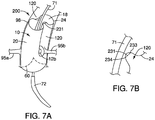
- FIGS. 7A-7B an alternative system 200 for maintaining perfusion of branch vessels is shown and described.
- the system 200 is similar to the system 100 of FIGS. 6A-6B , with a main exception that the graft 20 is secured to itself to form one or more temporary channels 120, as opposed to being secured to the delivery system 70 in the example of FIGS. 6A-6B .
- the system 200 comprises at least one suture 231 that is secured to the graft 20 in a manner that forms the shape of the temporary channel 120.
- the suture 231 may be secured near the distal end 24 of the graft 20 between spaced-apart first and second locations 233 and 234, as depicted in FIG. 7B .
- the dimensions of the suture 231 and its placement relative to locations 233 and 234 produces a tension that maintains the temporary channel 120 until the suture 231 is released.
- multiple sutures 231 may be longitudinally spaced apart between the distal end 24 of the graft 20 and the fenestration 12b, thereby maintaining the temporary channel 120 for a desired longitudinal distance between these locations.
- the temporary channel 120 may comprise a generally "U"-shaped channel external to the graft 20, as shown in FIGS. 7A-7B .
- the suture 231 may extend across the lumen 18 of the prosthesis 10, e.g., sewn to distal ends of the graft 20 at two locations spaced apart about 180 degrees. Such a suture across the lumen 18 may hold opposing sides of the graft 20 at a tension that maintains two temporary channels 120 in place, in the manner shown in FIG. 7A , until the suture is released.
- flow may advantageously be maintained to the coronary arteries during the endovascular procedure, even though the branch vessel prostheses 92a and 92b have not yet been set in place.
- the temporary channel 120 may be withdrawn by removal of the suture 231.
- the delivery system 70 may comprise a balloon, and radially outward expansion of the balloon against the suture 231 may cause breakage of the suture 231, thereby allowing the associated portion of the graft 20 to self-expand without restraint into full engagement with the ascending aorta 98, as shown in FIG. 6C .
- the suture 231 may comprise a biodegradable material and may dissolve after a predetermined period of time, thereby allowing the associated portion of the graft 20 to self-expand without restraint into full engagement with the ascending aorta 98.
- a trigger wire may be used to remove the suture 231, in a manner similar to that shown in FIGS. 6A-6B above. In any of these techniques, flow is advantageously maintained to the coronary arteries in the interim period required to ensure placement of the branch vessel prostheses 92a and 92b.
- the branch vessel prostheses 92a and 92b may be deployed at a later time in a subsequent procedure.
- one or more sutures 231 may maintain the temporary channel 120 to allow sufficient retrograde flow into the coronary arteries 95a and 95b to help sustain the patient while awaiting implantation of the branch prostheses 92a and 92b.
- the system 300 comprises at least one sheath 310 having a proximal end 314, and a distal end (not shown) extending outside of the patient's body. At least one aperture 312 is formed between the proximal and distal ends of the sheath 310.
- the proximal end 314 of the sheath 310 may be advanced into one of the patient's coronary arteries, as depicted in FIG. 8 .
- the sheath 310 may be delivered via any suitable vessel, including but not limited to the brachiocephalic artery.
- the aperture 312 of the sheath 310 is disposed distally beyond the distal end 24 of the graft 20, as the prosthesis 10 is being implanted. At least a portion of the sheath 310 is disposed adjacent to an exterior surface of the graft 20 while the prosthesis 10 is being implanted, and before the branch vessel prostheses 95a and 95b are introduced into their respective coronary arteries. In this manner, blood may flow through the valve 60, through the graft 20, and into the aperture 312, and then flow in a retrograde manner through the sheath 310 and into the coronary artery.
- flow may advantageously be maintained to the coronary arteries during the endovascular procedure, even though the branch vessel prostheses 92a and 92b have not yet been set in place.
- the sheath 310 may be withdrawn from the patient.
- the system 400 comprises at least one external support 410.
- the external support 410 is in the form of a stent framework 411 having proximal and distal ends 412 and 414, respectively.
- the stent framework 411 is disposed adjacent to the outer surface of the graft 20 in a manner such that it forms the shape of the temporary channel 120.
- the distal end 414 of the stent framework 411 may be disposed near the distal end 24 of the graft 20
- the proximal end 412 of the stent framework 411 may be disposed a short distance distal to the fenestration 12b, as depicted in FIG. 9 .
- the external support 410 may be deployed in conjunction with, or before, the partial deployment of the graft 20 as shown in FIG. 9 .
- the external support 410 is disposed adjacent to an exterior surface of the graft 20 while the prosthesis 10 is being implanted, and before the branch vessel prostheses 95a and 95b are introduced into their respective coronary arteries. Accordingly, blood may flow through the valve 60, through the graft 20, and then flow in a retrograde manner through the support 410 and into the coronary artery.
- flow may advantageously be maintained to the coronary arteries during the endovascular procedure, even though the branch vessel prostheses 92a and 92b have not yet been set in place.
- the support 410 may be withdrawn from the patient.
- the support 410 may be removed using a suitable technique such as pulling on a drawstring-like element to induce contraction of the support 410 to a smaller diameter and subsequent capture by a removal sheath.
- the distal end 414 of the support 410 may extend distally beyond the graft 20 such that the distal end 414 remains secured to the delivery device 70 throughout the procedure at a location distal to the graft 20, and then distal removal of the delivery device 70 (after placement of the branch vessel prostheses 92a and 92b) achieves a corresponding distal removal of the support 410.
- the branch vessel prostheses 92a and 92b may be deployed at a later time in a subsequent procedure.
- the support 410 may maintain a temporary channel to allow sufficient retrograde flow into the coronary arteries 95a and 95b to help sustain the patient's health.
- the prosthesis 10 alternatively may be deployed in other parts of a patient's arterial or venous system, or any suitable duct, passageway or vessel, and the various systems 100, 200, 300 and 400 may maintain flow into branch vessels other than the coronary arteries depending on use of the prosthesis 10. While various embodiments of the invention have been described, the invention is not to be restricted except in light of the attached claims.
Landscapes
- Health & Medical Sciences (AREA)
- Engineering & Computer Science (AREA)
- Biomedical Technology (AREA)
- Heart & Thoracic Surgery (AREA)
- Oral & Maxillofacial Surgery (AREA)
- Transplantation (AREA)
- Cardiology (AREA)
- Vascular Medicine (AREA)
- Life Sciences & Earth Sciences (AREA)
- Animal Behavior & Ethology (AREA)
- General Health & Medical Sciences (AREA)
- Public Health (AREA)
- Veterinary Medicine (AREA)
- Pulmonology (AREA)
- Gastroenterology & Hepatology (AREA)
- Prostheses (AREA)
Claims (12)
- Système de prothèse endoluminale (100, 200, 300, 400) comprenant une prothèse endoluminale (10), ladite prothèse (10) comprenant :un greffon (20) ayant un corps tubulaire comprenant des extrémités proximale et distale (22, 24), et des surfaces intérieure et extérieure, ledit greffon (20) étant adapté pour avoir des états partiellement et complètement déployés, et ledit greffon étant adapté pour former un canal temporaire (120, 310, 410) disposé à l'extérieur de la surface extérieure du greffon dans l'état partiellement déployé, le canal temporaire commençant à l'extrémité distale (24) du greffon, s'étendant le long d'une partie seulement d'une longueur longitudinale du greffon et se terminant avant l'extrémité proximale (22) du greffon, le canal temporaire étant adapté pour être retiré lorsque le greffon est dans l'état entièrement déployé ; etau moins un passage (12) disposé dans une paroi latérale du greffon (20) entre les extrémités proximale et distale (22, 24) du greffon, l'extrémité proximale du canal temporaire étant alignée avec le passage.
- Système (100, 200) selon la revendication 1, le canal temporaire (120) comprenant une forme en « U ».
- Système (100, 200, 300, 400) selon la revendication 1 ou 2, comprenant un remplacement de valve (60) disposé entre les extrémités proximale et distale (22, 24) du greffon (20).
- Système (200) selon la revendication 1, 2 ou 3, la forme du canal temporaire (120) étant maintenue par la fixation d'une première partie du greffon (20) à une seconde partie du greffon.
- Système (200) selon la revendication 4, la première partie du greffon (20) étant fixée à la seconde partie du greffon en utilisant au moins une suture (231).
- Système (200) selon la revendication 5, la suture comprenant un matériau biodégradable, et le canal temporaire (120) étant adapté pour être retiré lors de la dégradation de la suture (231).
- Système (200) selon la revendication 5, le canal temporaire (120) étant adapté pour être retiré par rupture de la suture (231) en utilisant une force externe.
- Système (300) selon l'une quelconque des revendications précédentes, le canal temporaire (120) comprenant une gaine (310) ayant une ouverture (312), l'ouverture étant disposée de manière distale par rapport à l'extrémité distale du greffon (20) dans l'état partiellement déployé, et une partie de la gaine étant disposée de manière adjacente à la surface extérieure du greffon dans l'état partiellement déployé.
- Système (400) selon l'une quelconque des revendications précédentes, le canal temporaire (120) comprenant une armature de stent amovible (411) adaptée pour être disposée à l'extérieur du greffon (20) dans l'état partiellement déployé.
- Système (100, 200, 300, 400) selon l'une quelconque des revendications précédentes, comprenant un remplacement de valve (60) disposé à l'intérieur d'au moins une partie du greffon (20).
- Système (100) selon l'une quelconque des revendications 1 à 3 ou 10, comprenant un système de distribution (70), la forme du canal temporaire (120) étant maintenue par la fixation d'une partie du greffon (20) au système de distribution.
- Système selon la revendication 11, comprenant un élément de couplage (131) fixé au greffon (20), et un fil (132) s'étendant le long du système de distribution (70), le canal amovible (120) étant maintenu lorsque le fil est couplé à l'élément de couplage du greffon, et le canal temporaire étant retiré lorsque le fil est libéré de son engagement avec le greffon.
Applications Claiming Priority (1)
| Application Number | Priority Date | Filing Date | Title |
|---|---|---|---|
| US13/793,695 US9808364B2 (en) | 2013-03-11 | 2013-03-11 | Systems and methods for maintaining perfusion of branch vessels |
Publications (2)
| Publication Number | Publication Date |
|---|---|
| EP2777608A1 EP2777608A1 (fr) | 2014-09-17 |
| EP2777608B1 true EP2777608B1 (fr) | 2021-12-29 |
Family
ID=50238323
Family Applications (1)
| Application Number | Title | Priority Date | Filing Date |
|---|---|---|---|
| EP14275047.0A Active EP2777608B1 (fr) | 2013-03-11 | 2014-03-10 | Système de prothèse endoluminale |
Country Status (2)
| Country | Link |
|---|---|
| US (1) | US9808364B2 (fr) |
| EP (1) | EP2777608B1 (fr) |
Cited By (13)
| Publication number | Priority date | Publication date | Assignee | Title |
|---|---|---|---|---|
| US11389291B2 (en) | 2013-04-04 | 2022-07-19 | Neovase Tiara Inc. | Methods and apparatus for delivering a prosthetic valve to a beating heart |
| US11389294B2 (en) | 2012-05-30 | 2022-07-19 | Neovasc Tiara Inc. | Methods and apparatus for loading a prosthesis onto a delivery system |
| US11413139B2 (en) | 2011-11-23 | 2022-08-16 | Neovasc Tiara Inc. | Sequentially deployed transcatheter mitral valve prosthesis |
| US11419720B2 (en) | 2010-05-05 | 2022-08-23 | Neovasc Tiara Inc. | Transcatheter mitral valve prosthesis |
| US11464631B2 (en) | 2016-11-21 | 2022-10-11 | Neovasc Tiara Inc. | Methods and systems for rapid retraction of a transcatheter heart valve delivery system |
| US11491006B2 (en) | 2019-04-10 | 2022-11-08 | Neovasc Tiara Inc. | Prosthetic valve with natural blood flow |
| US11497602B2 (en) | 2012-02-14 | 2022-11-15 | Neovasc Tiara Inc. | Methods and apparatus for engaging a valve prosthesis with tissue |
| US11602429B2 (en) | 2019-04-01 | 2023-03-14 | Neovasc Tiara Inc. | Controllably deployable prosthetic valve |
| US11737872B2 (en) | 2018-11-08 | 2023-08-29 | Neovasc Tiara Inc. | Ventricular deployment of a transcatheter mitral valve prosthesis |
| US11793640B2 (en) | 2017-08-25 | 2023-10-24 | Neovasc Tiara Inc. | Sequentially deployed transcatheter mitral valve prosthesis |
| US11998447B2 (en) | 2019-03-08 | 2024-06-04 | Neovasc Tiara Inc. | Retrievable prosthesis delivery system |
| US12109111B2 (en) | 2015-12-15 | 2024-10-08 | Neovasc Tiara Inc. | Transseptal delivery system |
| US12193932B2 (en) | 2016-01-29 | 2025-01-14 | Neovasc Tiara Inc. | Prosthetic valve for avoiding obstruction of outflow |
Families Citing this family (10)
| Publication number | Priority date | Publication date | Assignee | Title |
|---|---|---|---|---|
| CA2747610C (fr) | 2010-08-13 | 2014-09-16 | Cook Medical Technologies Llc | Fenetrage precanule |
| US9101455B2 (en) * | 2010-08-13 | 2015-08-11 | Cook Medical Technologies Llc | Preloaded wire for endoluminal device |
| US10524944B1 (en) * | 2014-01-29 | 2020-01-07 | W. L. Gore & Associates, Inc. | Delivery systems and methods of endoluminal delivery of branched vascular endoprosthetic devices |
| US10610393B2 (en) | 2016-03-24 | 2020-04-07 | Cook Medical Technologies Llc | Wire retention and release mechanisms |
| US10500079B2 (en) | 2016-10-27 | 2019-12-10 | Cook Medical Technologies Llc | Preloaded branch wire loop constraint |
| US10874501B2 (en) | 2016-12-28 | 2020-12-29 | Cook Medical Technologies Llc | Low profile stent graft having a check valve |
| IT201700031905A1 (it) * | 2017-03-23 | 2018-09-23 | Enrico Riccardo Ferrari | Endoprotesi aortica. |
| JP2021522037A (ja) * | 2018-04-25 | 2021-08-30 | シャンハイ チャンハイ ホスピタルShanghai Changhai Hospital | 上行大動脈ステントグラフト |
| CN112006811B (zh) * | 2019-05-28 | 2024-02-06 | 上海创心医学科技有限公司 | 一种血管重建装置 |
| CN115137526B (zh) * | 2021-03-31 | 2024-10-29 | 上海微创心脉医疗科技(集团)股份有限公司 | 一种覆膜支架及医用装置 |
Family Cites Families (22)
| Publication number | Priority date | Publication date | Assignee | Title |
|---|---|---|---|---|
| US5720776A (en) * | 1991-10-25 | 1998-02-24 | Cook Incorporated | Barb and expandable transluminal graft prosthesis for repair of aneurysm |
| US5387235A (en) * | 1991-10-25 | 1995-02-07 | Cook Incorporated | Expandable transluminal graft prosthesis for repair of aneurysm |
| US6015429A (en) * | 1994-09-08 | 2000-01-18 | Gore Enterprise Holdings, Inc. | Procedures for introducing stents and stent-grafts |
| WO1996036297A1 (fr) * | 1995-05-19 | 1996-11-21 | Kanji Inoue | Instrument de transplantation, procede pour le courber et procede pour le transplanter |
| US5948017A (en) * | 1997-10-12 | 1999-09-07 | Taheri; Syde A. | Modular graft assembly |
| US6458153B1 (en) * | 1999-12-31 | 2002-10-01 | Abps Venture One, Ltd. | Endoluminal cardiac and venous valve prostheses and methods of manufacture and delivery thereof |
| US6676699B2 (en) * | 2002-04-26 | 2004-01-13 | Medtronic Ave, Inc | Stent graft with integrated valve device and method |
| AU2003258337A1 (en) * | 2002-08-23 | 2004-03-11 | Cook Incorporated | Asymmetric stent graft attachment |
| US7998186B2 (en) * | 2003-10-14 | 2011-08-16 | William A. Cook Australia Pty. Ltd. | Introducer for a side branch device |
| US8043354B2 (en) * | 2004-06-16 | 2011-10-25 | William A. Cook Australia Pty. Ltd. | Thoracic deployment device and stent graft |
| US20070168013A1 (en) * | 2006-01-19 | 2007-07-19 | Myles Douglas | Vascular graft and deployment system |
| WO2008057569A1 (fr) * | 2006-11-07 | 2008-05-15 | William A. Cook Australia Pty. Ltd. | Endoprothèse pour le traitement d'urgence d'une rupture d'un vaisseau |
| US20090270971A1 (en) * | 2008-04-24 | 2009-10-29 | Medtronic Vascular, Inc. | Prosthesis Fixation Apparatus and Methods |
| EP2815724B2 (fr) * | 2008-07-15 | 2024-03-13 | St. Jude Medical, Inc. | Modèles de collerette pour valve cardiaque prothétique repliable et redéployable et applications techniques complémentaires |
| GB2464977B (en) * | 2008-10-31 | 2010-11-03 | William Cook Europe As | Introducer for deploying a stent graft in a curved lumen and stent graft therefor |
| AU2009200350B1 (en) * | 2009-02-02 | 2009-07-16 | Cook Incorporated | Preloaded stent graft delivery device |
| CN102458303A (zh) | 2009-04-02 | 2012-05-16 | 医学研究,基础设施和卫生服务基金的特拉维夫医疗中心 | 支架移植物穿孔 |
| US20100268318A1 (en) * | 2009-04-16 | 2010-10-21 | Medtronic Vascular, Inc. | Prosthesis for Antegrade Deployment |
| US8771333B2 (en) * | 2009-06-23 | 2014-07-08 | Cordis Corporation | Stent-graft securement device |
| CA3009244C (fr) * | 2009-06-23 | 2020-04-28 | Endospan Ltd. | Protheses vasculaires utilisees pour le traitement des anevrismes |
| CA2748206C (fr) | 2010-08-21 | 2015-06-23 | Blayne A. Roeder | Prothese a fenestration pivotante |
| US9662196B2 (en) * | 2011-09-27 | 2017-05-30 | Cook Medical Technologies Llc | Endoluminal prosthesis with steerable branch |
-
2013
- 2013-03-11 US US13/793,695 patent/US9808364B2/en active Active
-
2014
- 2014-03-10 EP EP14275047.0A patent/EP2777608B1/fr active Active
Cited By (18)
| Publication number | Priority date | Publication date | Assignee | Title |
|---|---|---|---|---|
| US11419720B2 (en) | 2010-05-05 | 2022-08-23 | Neovasc Tiara Inc. | Transcatheter mitral valve prosthesis |
| US12053369B2 (en) | 2011-11-23 | 2024-08-06 | Neovasc Tiara Inc. | Sequentially deployed transcatheter mitral valve prosthesis |
| US11413139B2 (en) | 2011-11-23 | 2022-08-16 | Neovasc Tiara Inc. | Sequentially deployed transcatheter mitral valve prosthesis |
| US11497602B2 (en) | 2012-02-14 | 2022-11-15 | Neovasc Tiara Inc. | Methods and apparatus for engaging a valve prosthesis with tissue |
| US12138159B2 (en) | 2012-02-14 | 2024-11-12 | Neovasc Tiara Inc. | Methods and apparatus for engaging a valve prosthesis with tissue |
| US11389294B2 (en) | 2012-05-30 | 2022-07-19 | Neovasc Tiara Inc. | Methods and apparatus for loading a prosthesis onto a delivery system |
| US11617650B2 (en) | 2012-05-30 | 2023-04-04 | Neovasc Tiara Inc. | Methods and apparatus for loading a prosthesis onto a delivery system |
| US11389291B2 (en) | 2013-04-04 | 2022-07-19 | Neovase Tiara Inc. | Methods and apparatus for delivering a prosthetic valve to a beating heart |
| US12109111B2 (en) | 2015-12-15 | 2024-10-08 | Neovasc Tiara Inc. | Transseptal delivery system |
| US12193932B2 (en) | 2016-01-29 | 2025-01-14 | Neovasc Tiara Inc. | Prosthetic valve for avoiding obstruction of outflow |
| US11464631B2 (en) | 2016-11-21 | 2022-10-11 | Neovasc Tiara Inc. | Methods and systems for rapid retraction of a transcatheter heart valve delivery system |
| US12201524B2 (en) | 2016-11-21 | 2025-01-21 | Neovasc Tiara Inc. | Methods and systems for rapid retraction of a transcatheter heart valve delivery system |
| US11793640B2 (en) | 2017-08-25 | 2023-10-24 | Neovasc Tiara Inc. | Sequentially deployed transcatheter mitral valve prosthesis |
| US11737872B2 (en) | 2018-11-08 | 2023-08-29 | Neovasc Tiara Inc. | Ventricular deployment of a transcatheter mitral valve prosthesis |
| US11998447B2 (en) | 2019-03-08 | 2024-06-04 | Neovasc Tiara Inc. | Retrievable prosthesis delivery system |
| US11602429B2 (en) | 2019-04-01 | 2023-03-14 | Neovasc Tiara Inc. | Controllably deployable prosthetic valve |
| US12036117B2 (en) | 2019-04-10 | 2024-07-16 | Neovasc Tiara Inc. | Prosthetic valve with natural blood flow |
| US11491006B2 (en) | 2019-04-10 | 2022-11-08 | Neovasc Tiara Inc. | Prosthetic valve with natural blood flow |
Also Published As
| Publication number | Publication date |
|---|---|
| EP2777608A1 (fr) | 2014-09-17 |
| US20140257453A1 (en) | 2014-09-11 |
| US9808364B2 (en) | 2017-11-07 |
Similar Documents
| Publication | Publication Date | Title |
|---|---|---|
| EP2777608B1 (fr) | Système de prothèse endoluminale | |
| US12245936B2 (en) | Stent structures for use with valve replacements | |
| US10842618B2 (en) | Endoluminal prosthesis comprising a valve and an axially extendable segment | |
| EP2478869B1 (fr) | Prothèse valvulaire cardiaque | |
| EP1729685B1 (fr) | Greffe endoluminale avec valve prothetique | |
| EP2491892B1 (fr) | Greffe d'endoprothèse avec agencement de soupape et ensemble d'introducteur correspondant | |
| US9839542B2 (en) | Mobile external coupling for branch vessel connection | |
| EP2606852B1 (fr) | Prothèse endoluminale comprenant un remplacement de valve et au moins une fenestration | |
| US20190069986A1 (en) | Endoluminal prosthesis with an aortic sinus stent assembly | |
| EP4666987A1 (fr) | Prothèse endoluminale transcathéter, système de pose la contenant et procédé d'implantation de la prothèse | |
| EP4666986A1 (fr) | Système de pose contenant une prothèse endoluminale transcathéter |
Legal Events
| Date | Code | Title | Description |
|---|---|---|---|
| 17P | Request for examination filed |
Effective date: 20140310 |
|
| AK | Designated contracting states |
Kind code of ref document: A1 Designated state(s): AL AT BE BG CH CY CZ DE DK EE ES FI FR GB GR HR HU IE IS IT LI LT LU LV MC MK MT NL NO PL PT RO RS SE SI SK SM TR |
|
| AX | Request for extension of the european patent |
Extension state: BA ME |
|
| PUAI | Public reference made under article 153(3) epc to a published international application that has entered the european phase |
Free format text: ORIGINAL CODE: 0009012 |
|
| R17P | Request for examination filed (corrected) |
Effective date: 20150311 |
|
| RBV | Designated contracting states (corrected) |
Designated state(s): AL AT BE BG CH CY CZ DE DK EE ES FI FR GB GR HR HU IE IS IT LI LT LU LV MC MK MT NL NO PL PT RO RS SE SI SK SM TR |
|
| 17Q | First examination report despatched |
Effective date: 20160613 |
|
| STAA | Information on the status of an ep patent application or granted ep patent |
Free format text: STATUS: EXAMINATION IS IN PROGRESS |
|
| GRAP | Despatch of communication of intention to grant a patent |
Free format text: ORIGINAL CODE: EPIDOSNIGR1 |
|
| STAA | Information on the status of an ep patent application or granted ep patent |
Free format text: STATUS: GRANT OF PATENT IS INTENDED |
|
| RIC1 | Information provided on ipc code assigned before grant |
Ipc: A61F 2/844 20130101ALN20210721BHEP Ipc: A61F 2/24 20060101ALN20210721BHEP Ipc: A61F 2/07 20130101AFI20210721BHEP |
|
| INTG | Intention to grant announced |
Effective date: 20210806 |
|
| GRAS | Grant fee paid |
Free format text: ORIGINAL CODE: EPIDOSNIGR3 |
|
| GRAA | (expected) grant |
Free format text: ORIGINAL CODE: 0009210 |
|
| STAA | Information on the status of an ep patent application or granted ep patent |
Free format text: STATUS: THE PATENT HAS BEEN GRANTED |
|
| AK | Designated contracting states |
Kind code of ref document: B1 Designated state(s): AL AT BE BG CH CY CZ DE DK EE ES FI FR GB GR HR HU IE IS IT LI LT LU LV MC MK MT NL NO PL PT RO RS SE SI SK SM TR |
|
| REG | Reference to a national code |
Ref country code: GB Ref legal event code: FG4D |
|
| REG | Reference to a national code |
Ref country code: CH Ref legal event code: EP |
|
| REG | Reference to a national code |
Ref country code: DE Ref legal event code: R096 Ref document number: 602014081899 Country of ref document: DE |
|
| REG | Reference to a national code |
Ref country code: AT Ref legal event code: REF Ref document number: 1458128 Country of ref document: AT Kind code of ref document: T Effective date: 20220115 |
|
| REG | Reference to a national code |
Ref country code: IE Ref legal event code: FG4D |
|
| REG | Reference to a national code |
Ref country code: LT Ref legal event code: MG9D |
|
| PG25 | Lapsed in a contracting state [announced via postgrant information from national office to epo] |
Ref country code: RS Free format text: LAPSE BECAUSE OF FAILURE TO SUBMIT A TRANSLATION OF THE DESCRIPTION OR TO PAY THE FEE WITHIN THE PRESCRIBED TIME-LIMIT Effective date: 20211229 Ref country code: LT Free format text: LAPSE BECAUSE OF FAILURE TO SUBMIT A TRANSLATION OF THE DESCRIPTION OR TO PAY THE FEE WITHIN THE PRESCRIBED TIME-LIMIT Effective date: 20211229 Ref country code: FI Free format text: LAPSE BECAUSE OF FAILURE TO SUBMIT A TRANSLATION OF THE DESCRIPTION OR TO PAY THE FEE WITHIN THE PRESCRIBED TIME-LIMIT Effective date: 20211229 Ref country code: BG Free format text: LAPSE BECAUSE OF FAILURE TO SUBMIT A TRANSLATION OF THE DESCRIPTION OR TO PAY THE FEE WITHIN THE PRESCRIBED TIME-LIMIT Effective date: 20220329 |
|
| REG | Reference to a national code |
Ref country code: NL Ref legal event code: MP Effective date: 20211229 |
|
| REG | Reference to a national code |
Ref country code: AT Ref legal event code: MK05 Ref document number: 1458128 Country of ref document: AT Kind code of ref document: T Effective date: 20211229 |
|
| PG25 | Lapsed in a contracting state [announced via postgrant information from national office to epo] |
Ref country code: SE Free format text: LAPSE BECAUSE OF FAILURE TO SUBMIT A TRANSLATION OF THE DESCRIPTION OR TO PAY THE FEE WITHIN THE PRESCRIBED TIME-LIMIT Effective date: 20211229 Ref country code: NO Free format text: LAPSE BECAUSE OF FAILURE TO SUBMIT A TRANSLATION OF THE DESCRIPTION OR TO PAY THE FEE WITHIN THE PRESCRIBED TIME-LIMIT Effective date: 20220329 Ref country code: LV Free format text: LAPSE BECAUSE OF FAILURE TO SUBMIT A TRANSLATION OF THE DESCRIPTION OR TO PAY THE FEE WITHIN THE PRESCRIBED TIME-LIMIT Effective date: 20211229 Ref country code: HR Free format text: LAPSE BECAUSE OF FAILURE TO SUBMIT A TRANSLATION OF THE DESCRIPTION OR TO PAY THE FEE WITHIN THE PRESCRIBED TIME-LIMIT Effective date: 20211229 Ref country code: GR Free format text: LAPSE BECAUSE OF FAILURE TO SUBMIT A TRANSLATION OF THE DESCRIPTION OR TO PAY THE FEE WITHIN THE PRESCRIBED TIME-LIMIT Effective date: 20220330 |
|
| PG25 | Lapsed in a contracting state [announced via postgrant information from national office to epo] |
Ref country code: NL Free format text: LAPSE BECAUSE OF FAILURE TO SUBMIT A TRANSLATION OF THE DESCRIPTION OR TO PAY THE FEE WITHIN THE PRESCRIBED TIME-LIMIT Effective date: 20211229 |
|
| PG25 | Lapsed in a contracting state [announced via postgrant information from national office to epo] |
Ref country code: SM Free format text: LAPSE BECAUSE OF FAILURE TO SUBMIT A TRANSLATION OF THE DESCRIPTION OR TO PAY THE FEE WITHIN THE PRESCRIBED TIME-LIMIT Effective date: 20211229 Ref country code: SK Free format text: LAPSE BECAUSE OF FAILURE TO SUBMIT A TRANSLATION OF THE DESCRIPTION OR TO PAY THE FEE WITHIN THE PRESCRIBED TIME-LIMIT Effective date: 20211229 Ref country code: RO Free format text: LAPSE BECAUSE OF FAILURE TO SUBMIT A TRANSLATION OF THE DESCRIPTION OR TO PAY THE FEE WITHIN THE PRESCRIBED TIME-LIMIT Effective date: 20211229 Ref country code: PT Free format text: LAPSE BECAUSE OF FAILURE TO SUBMIT A TRANSLATION OF THE DESCRIPTION OR TO PAY THE FEE WITHIN THE PRESCRIBED TIME-LIMIT Effective date: 20220429 Ref country code: ES Free format text: LAPSE BECAUSE OF FAILURE TO SUBMIT A TRANSLATION OF THE DESCRIPTION OR TO PAY THE FEE WITHIN THE PRESCRIBED TIME-LIMIT Effective date: 20211229 Ref country code: EE Free format text: LAPSE BECAUSE OF FAILURE TO SUBMIT A TRANSLATION OF THE DESCRIPTION OR TO PAY THE FEE WITHIN THE PRESCRIBED TIME-LIMIT Effective date: 20211229 Ref country code: CZ Free format text: LAPSE BECAUSE OF FAILURE TO SUBMIT A TRANSLATION OF THE DESCRIPTION OR TO PAY THE FEE WITHIN THE PRESCRIBED TIME-LIMIT Effective date: 20211229 |
|
| PG25 | Lapsed in a contracting state [announced via postgrant information from national office to epo] |
Ref country code: PL Free format text: LAPSE BECAUSE OF FAILURE TO SUBMIT A TRANSLATION OF THE DESCRIPTION OR TO PAY THE FEE WITHIN THE PRESCRIBED TIME-LIMIT Effective date: 20211229 Ref country code: AT Free format text: LAPSE BECAUSE OF FAILURE TO SUBMIT A TRANSLATION OF THE DESCRIPTION OR TO PAY THE FEE WITHIN THE PRESCRIBED TIME-LIMIT Effective date: 20211229 |
|
| PG25 | Lapsed in a contracting state [announced via postgrant information from national office to epo] |
Ref country code: IS Free format text: LAPSE BECAUSE OF FAILURE TO SUBMIT A TRANSLATION OF THE DESCRIPTION OR TO PAY THE FEE WITHIN THE PRESCRIBED TIME-LIMIT Effective date: 20220429 |
|
| REG | Reference to a national code |
Ref country code: DE Ref legal event code: R097 Ref document number: 602014081899 Country of ref document: DE |
|
| PG25 | Lapsed in a contracting state [announced via postgrant information from national office to epo] |
Ref country code: MC Free format text: LAPSE BECAUSE OF FAILURE TO SUBMIT A TRANSLATION OF THE DESCRIPTION OR TO PAY THE FEE WITHIN THE PRESCRIBED TIME-LIMIT Effective date: 20211229 Ref country code: DK Free format text: LAPSE BECAUSE OF FAILURE TO SUBMIT A TRANSLATION OF THE DESCRIPTION OR TO PAY THE FEE WITHIN THE PRESCRIBED TIME-LIMIT Effective date: 20211229 Ref country code: AL Free format text: LAPSE BECAUSE OF FAILURE TO SUBMIT A TRANSLATION OF THE DESCRIPTION OR TO PAY THE FEE WITHIN THE PRESCRIBED TIME-LIMIT Effective date: 20211229 |
|
| REG | Reference to a national code |
Ref country code: CH Ref legal event code: PL |
|
| PLBE | No opposition filed within time limit |
Free format text: ORIGINAL CODE: 0009261 |
|
| STAA | Information on the status of an ep patent application or granted ep patent |
Free format text: STATUS: NO OPPOSITION FILED WITHIN TIME LIMIT |
|
| 26N | No opposition filed |
Effective date: 20220930 |
|
| REG | Reference to a national code |
Ref country code: BE Ref legal event code: MM Effective date: 20220331 |
|
| PG25 | Lapsed in a contracting state [announced via postgrant information from national office to epo] |
Ref country code: LU Free format text: LAPSE BECAUSE OF NON-PAYMENT OF DUE FEES Effective date: 20220310 Ref country code: LI Free format text: LAPSE BECAUSE OF NON-PAYMENT OF DUE FEES Effective date: 20220331 Ref country code: FR Free format text: LAPSE BECAUSE OF NON-PAYMENT OF DUE FEES Effective date: 20220331 Ref country code: CH Free format text: LAPSE BECAUSE OF NON-PAYMENT OF DUE FEES Effective date: 20220331 |
|
| PG25 | Lapsed in a contracting state [announced via postgrant information from national office to epo] |
Ref country code: SI Free format text: LAPSE BECAUSE OF FAILURE TO SUBMIT A TRANSLATION OF THE DESCRIPTION OR TO PAY THE FEE WITHIN THE PRESCRIBED TIME-LIMIT Effective date: 20211229 Ref country code: BE Free format text: LAPSE BECAUSE OF NON-PAYMENT OF DUE FEES Effective date: 20220331 |
|
| PG25 | Lapsed in a contracting state [announced via postgrant information from national office to epo] |
Ref country code: IT Free format text: LAPSE BECAUSE OF FAILURE TO SUBMIT A TRANSLATION OF THE DESCRIPTION OR TO PAY THE FEE WITHIN THE PRESCRIBED TIME-LIMIT Effective date: 20211229 |
|
| P01 | Opt-out of the competence of the unified patent court (upc) registered |
Effective date: 20230602 |
|
| PG25 | Lapsed in a contracting state [announced via postgrant information from national office to epo] |
Ref country code: HU Free format text: LAPSE BECAUSE OF FAILURE TO SUBMIT A TRANSLATION OF THE DESCRIPTION OR TO PAY THE FEE WITHIN THE PRESCRIBED TIME-LIMIT; INVALID AB INITIO Effective date: 20140310 |
|
| PG25 | Lapsed in a contracting state [announced via postgrant information from national office to epo] |
Ref country code: MK Free format text: LAPSE BECAUSE OF FAILURE TO SUBMIT A TRANSLATION OF THE DESCRIPTION OR TO PAY THE FEE WITHIN THE PRESCRIBED TIME-LIMIT Effective date: 20211229 Ref country code: CY Free format text: LAPSE BECAUSE OF FAILURE TO SUBMIT A TRANSLATION OF THE DESCRIPTION OR TO PAY THE FEE WITHIN THE PRESCRIBED TIME-LIMIT Effective date: 20211229 |
|
| PG25 | Lapsed in a contracting state [announced via postgrant information from national office to epo] |
Ref country code: MT Free format text: LAPSE BECAUSE OF FAILURE TO SUBMIT A TRANSLATION OF THE DESCRIPTION OR TO PAY THE FEE WITHIN THE PRESCRIBED TIME-LIMIT Effective date: 20211229 |
|
| PG25 | Lapsed in a contracting state [announced via postgrant information from national office to epo] |
Ref country code: TR Free format text: LAPSE BECAUSE OF FAILURE TO SUBMIT A TRANSLATION OF THE DESCRIPTION OR TO PAY THE FEE WITHIN THE PRESCRIBED TIME-LIMIT Effective date: 20211229 |
|
| PGFP | Annual fee paid to national office [announced via postgrant information from national office to epo] |
Ref country code: GB Payment date: 20260319 Year of fee payment: 13 |
|
| PGFP | Annual fee paid to national office [announced via postgrant information from national office to epo] |
Ref country code: IE Payment date: 20260318 Year of fee payment: 13 Ref country code: DE Payment date: 20260320 Year of fee payment: 13 |