EP2777772A2 - Bremssysteme für das assistierte Abseilen mit einem Hebelentkopplungsmechanismus - Google Patents
Bremssysteme für das assistierte Abseilen mit einem Hebelentkopplungsmechanismus Download PDFInfo
- Publication number
- EP2777772A2 EP2777772A2 EP14159573.6A EP14159573A EP2777772A2 EP 2777772 A2 EP2777772 A2 EP 2777772A2 EP 14159573 A EP14159573 A EP 14159573A EP 2777772 A2 EP2777772 A2 EP 2777772A2
- Authority
- EP
- European Patent Office
- Prior art keywords
- lever
- camming
- state
- housing
- respect
- Prior art date
- Legal status (The legal status is an assumption and is not a legal conclusion. Google has not performed a legal analysis and makes no representation as to the accuracy of the status listed.)
- Withdrawn
Links
- 230000007246 mechanism Effects 0.000 title claims abstract description 312
- 230000008878 coupling Effects 0.000 claims description 48
- 238000010168 coupling process Methods 0.000 claims description 48
- 238000005859 coupling reaction Methods 0.000 claims description 48
- 230000008901 benefit Effects 0.000 claims description 10
- 238000004891 communication Methods 0.000 claims description 2
- 241001503987 Clematis vitalba Species 0.000 abstract description 39
- 230000036461 convulsion Effects 0.000 description 5
- 230000001133 acceleration Effects 0.000 description 4
- 230000000694 effects Effects 0.000 description 3
- 208000027418 Wounds and injury Diseases 0.000 description 2
- 230000009194 climbing Effects 0.000 description 2
- 230000006378 damage Effects 0.000 description 2
- 208000014674 injury Diseases 0.000 description 2
- 230000007704 transition Effects 0.000 description 2
- 238000001514 detection method Methods 0.000 description 1
- 230000000977 initiatory effect Effects 0.000 description 1
- 238000012423 maintenance Methods 0.000 description 1
Images


Classifications
-
- A—HUMAN NECESSITIES
- A62—LIFE-SAVING; FIRE-FIGHTING
- A62B—DEVICES, APPARATUS OR METHODS FOR LIFE-SAVING
- A62B1/00—Devices for lowering persons from buildings or the like
- A62B1/06—Devices for lowering persons from buildings or the like by making use of rope-lowering devices
- A62B1/14—Devices for lowering persons from buildings or the like by making use of rope-lowering devices with brakes sliding on the rope
Definitions
- the invention generally relates to belay devices with assisted braking, self-arresting belay devices, and automatic locking belay devices for climbing related activities.
- the present invention relates to an assisted braking belay system with a lever disengagement mechanism.
- a belay device is used by a belayer in the act of belaying a climber.
- the belay device is coupled to the belayer, who feeds excess rope to the climber through the belay device as the climber ascends.
- the belayer and belay device selectively hold or lock a region of the rope, thereby tensioning the rope between the belayer and climber and arresting the climber's fall.
- Belay devices are also used to lower the climber by controlling the speed at which excess rope is fed through the belay device while the rope is under tension from the climber's weight.
- belay device One type of belay device is generally referred to as a belay device with assisted braking, a self-arresting belay device, an automatic belay device, and/or an auto-locking belay device because it contains a mechanism to automatically increase the friction on the rope in the event of a climber fall.
- a second type of belay device is referred to as passive because it requires the belayer to manually act to increase the friction on the rope in the event of a climber fall.
- an auto-locking belay device is preferred because it increases the likelihood of arresting a climber's fall despite the actions of the belayer.
- a common type of auto-locking belay system includes some form of camming mechanism or surface.
- the system also generally includes a lever mechanism.
- the lever mechanism enables the belayer to selectively disengage the camming mechanism or surface from the rope to reduce friction and allow rope to feed through the device, thereby lowering the climber.
- Lever mechanisms generally include a retractable elongated structure that enables a mechanical advantage upon the camming mechanism or surface.
- One of the problems or limitations with conventional auto-locking belay devices is the ability for the lever mechanism to completely disengage the camming mechanism or surface and remove substantially all friction from the rope while the climber is being lowered. If substantially all of the friction is eliminated at the belay device while the climber is weighting the rope, the climber will likely descend at a high velocity, which may cause injury upon impact with the ground.
- an assisted braking belay device that includes a lever disengagement mechanism that automatically reengages the camming mechanism or surface if the lever is engaged in an improper manner.
- the present invention relates to assisted braking belay systems.
- One embodiment of the present invention relates to an assisted braking belay system including a housing, a camming mechanism, and a lever mechanism with a lever disengagement mechanism.
- the housing may include a substantially enclosed rope channel through which a rope may extend to the climber.
- the camming mechanism is moveably coupled to the housing and configured to automatically engage a camming surface upon a rope across the rope channel if the rope translates through the channel at a particular acceleration rate.
- the lever mechanism enables a belayer to selectively disengage the camming mechanism and release the camming surface from the rope, thereby allowing the rope to translate through the rope channel.
- the lever disengagement mechanism is configured to automatically disengage the lever mechanism from the camming mechanism if the lever is over-rotated with respect to the housing, thereby enabling the camming mechanism to automatically reengage and apply friction upon the rope.
- Embodiments of the present invention represent a significant advance in the field of automatic belay systems.
- conventional automatic belay systems generally include a lever mechanism to selectively disengage the camming mechanism while lowering the climber.
- the belayer may over-extend the lever and disengage the camming mechanism to a degree that the climber descends at a very high speed, which may result in injury upon impact with the ground.
- Embodiments of the present invention incorporate a lever disengagement mechanism that automatically disengages the lever mechanism from the camming mechanism, thereby allowing the camming mechanism to automatically reengage the camming surface upon the rope and arrest the climber from further descent.
- an assisted braking belay system including a housing, a camming mechanism, and a lever mechanism with a lever disengagement mechanism.
- the housing may include a substantially enclosed rope channel through which a rope may extend to the climber.
- the camming mechanism is moveably coupled to the housing and configured to automatically engage a camming surface upon a rope across the rope channel if the rope translates through the channel at a particular accelerate rate.
- the lever mechanism enables a belayer to selectively disengage the camming mechanism and release the camming surface from the rope, thereby allowing the rope to translate through the rope channel.
- the lever disengagement mechanism is configured to automatically disengage the lever mechanism from the camming mechanism if the lever is over-rotated with respect to the housing, thereby enabling the camming mechanism to automatically reengage and apply friction upon the rope. Also, while embodiments are described in reference to an automatic belay system with a lever disengagement mechanism, it will be appreciated that the teachings of the present invention are applicable to other areas.
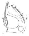
- FIG. 1-5 illustrate one embodiment of an assisted braking belay system with a lever mechanism in accordance with embodiments of the present invention, designated generally at 100.
- the assisted braking belay system 100 is designed to be used by a belayer in the act of belaying a climber (not shown).
- the act of belaying a climber includes coupling the belay system to the belayer and feeding a rope 110 through the system corresponding to the rate of controlled ascent or descent of the climber. Therefore, as the climber ascends a particular distance, the belayer feeds a corresponding distance of rope.
- the belay system 100 may be referred to as automatic or assisted because it includes at least one mechanism that automatically locks or applies a high degree of friction upon a section of the rope 110 if the rope accelerates or jerks above a particular rate. For example, if the climber falls, the climber's falling force will impart tension on the rope, thereby causing the rope to accelerate or jerk through the system 100 at a particular rate.
- the system 100 generally includes a housing 120, a camming mechanism 140, and a lever mechanism 160.
- the housing 120 includes an open state ( Figures 3-4 ) and a closed state ( Figures 1-2 ).
- the camming mechanism 140 includes a cammed state ( Figures 5-8 and 10-11 ) and a free state ( Figures 1-4 and 9 ).
- the lever mechanism 160 includes an extended state ( Figures 5-11 ) and a retracted state ( Figures 1-4 ).
- specific figures are utilized to illustrate the components and operations of the housing 120, camming mechanism 140, and lever mechanism 160.
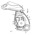
- the components of the housing 120 are specifically illustrated and designated in detail in Figure 4 .
- the components of the camming mechanism 140 are specifically illustrated and designated in detail in Figure 3 .
- the housing 120 further includes a rope channel 128, a top plate 124, a bottom plate 122, an opening 130, and a coupler 126.
- the open state of the housing 120 illustrated in Figure 4 includes the top plate 124 rotated or pivoted about the coupler 126 from the bottom plate 122.
- the top plate 124 may be rotatably coupled to the bottom plate 122 at an off-axis angle to enable the top plate to articulate over the camming mechanism 140 and clutch mechanism 160 in the closed state.
- the term off-axis angle refers to an angle that is at least five degrees off orthogonal to the lengthwise axis of the housing 120.
- Figure 3 illustrates the housing 120 with a substantially horizontal axis, and the top plate 124 is configured to rotate about an axis that is at least five degrees off planar.
- the optional off-axis angle provides a greater internal region between the top and bottom plates 124, 122, thereby providing more space for the camming mechanism 140 and clutch mechanism 160 in the closed state of the housing 120.
- the open state of the housing 120 is used to load a rope 110 into the rope channel 128 ( Figure 3 ).
- a user specifically orients the rope in a clockwise manner extending to the climber.
- the illustrated left end or clockwise termination of the rope channel 128 should be configured with a rope 110 portion that extends directly to the climber.
- the illustrated right end or clockwise initiation of the rope channel 128 should be configured with a rope 110 portion that does not extend to the climber.
- the user loads the rope 110 into the rope channel 128 of the bottom portion 122 of the housing 120 in the clockwise orientation illustrated and described.
- the user then rotates or pivots the top plate 124 over the bottom plate 122 (ie.
- the closed state of the housing 120 also includes aligning the opening 130 on both the top and bottom plates 124, 122.
- a user may extend a carabiner or other releasable coupling device through the aligned openings 130 and the user's harness (not shown) so as to couple the system 100 to the user or belayer.
- the act of extending a coupler through the openings 130 of both the top and bottom plates 124, 122 locks the housing 120 into the closed state by preventing the top plate 124 from rotating and/or exposing the rope 110 and rope channel 128.
- This form of releasably coupling and securing an assisted braking belay system to a user/belayer is well known to those skilled in the art.
- the automatic or assisted braking mechanism is the camming mechanism 140, which includes a free state ( Figure 3 ) and a cammed state ( Figures 5-6 ).
- the camming mechanism 140 is biased toward the free state by some form of biasing mechanism.
- the camming mechanism 140 is shaped and oriented within the system 100 such that it is in a translatable communication with the rope 110 as it translates through the belay system.
- the components of the camming mechanism 140 are illustrated and designated in detail in Figure 3 .
- the illustrated camming mechanism 140 includes a camming surface 142, a bearing surface 144, and a camming rotation point 146.
- the camming mechanism 140 may be transitioned from the free state to the cammed state by overcoming a biasing force and rotating about the camming rotation point 146 with respect to the bottom plate 122 of the housing.
- the bearing surface 144 is oriented and shaped such that a clockwise manual translation of the rope 110 through the rope channel 128 forces the rope 110 to contact and impart a force upon the bearing surface 144.
- the bearing surface 144 may be concave-shaped and protrude into the rope channel 128 for purposes of maintaining translational forces of the rope 110 upon the bearing surface 144. The maintenance of translation forces enables the bearing surface 144 to essentially detect the acceleration rate of the rope 110 through the rope channel 128.
- the camming mechanism 140 will rotate about the camming rotation point 146 with respect to the housing 120 so as to pivot or engage a portion of the camming surface 142 upon the rope 110 within the rope channel 128 (ie. transition from the free state to the cammed state).
- the engagement of the camming surface 142 upon the rope 110 may include translating a portion of the camming surface 142 across the rope channel 142 and restricting the rope channel 128 cross-sectional area, thereby increasing a translational friction force upon the rope 110 between the camming surface 142 and the housing 120.
- the rope channel 128 is cross-sectionally restricted to a diameter smaller than the diameter of the rope 110, the translational friction force upon the rope 110 will increase and the translational rate of the rope 110 will decrease.
- the engagement of the cammed state may eventually entirely arrest the rope 110 translation through the rope channel 128 of the system 100 once a sufficient amount of translational friction force is applied to the rope 110 with respect to a rope 110 translation rate prior to engagement.
- the camming surface 142 and bearing surfaces 144 are also shaped and configured with respect to the rope channel 128 such that once the rope is arrested, the cammed state will be maintained while a sufficient tensile strength is maintained on the rope 110.
- the specific shape of the bearing surface 144, camming surface 142, cam rotation point 146, biasing mechanism, and rope channel 128 all contribute to the detection of the minimum rope translation acceleration rate or jerk upon the bearing surface 144.
- the camming mechanism 140 further includes a lever 148 intercoupled with the camming surface 142 and bearing surface 142 to provide a mechanical rotational advantage.
- the lever 142 may be used by the user to rotate the camming mechanism 140 with respect to the housing 120 to enable selective clockwise rope 110 translation while a particular tensile force is still on the rope 110.
- the camming mechanism 140 is configured to automatically transition from the cammed state to the free state once a particular tensile force is removed from the rope 110.
- various alternative camming mechanism 140 designs may be implemented in accordance with embodiments of the present invention, such as alternative camming/bearing surface shapes, coupling orientations, coupling frictional forces, etc.
- One skilled in the art will understand the operation of the camming mechanism 140 from the description above and the referenced figures.
- the rope 110 is properly loaded into the rope channel 128, the housing 120 is in the closed state, the camming mechanism 140 is in the biased free state, and the system 100 is releasably coupled to the user/belayer.
- the belayer is able to sequentially feed or translate rope in a clockwise manner to the climber to enable ascent. If the climber falls, the rope 110 will accelerate or jerk through the system 100, causing a force upon the bearing surface 144. Once the force upon the bearing surface 144 overcomes the biasing force, the camming mechanism 140 will rotate, causing the camming surface to translate across the rope channel and impart a frictional force upon the rope 110.
- the rope translation will cease, thereby fixing the rope length between the belayer and climber.
- the tensile force of the rope will maintain the cammed state and prevent further rope translation.
- This rope length fixing between the belayer and climber will have the effect of arresting the climber's fall and ceasing any further descent.
- the climber may resume climbing, thereby removing the tensile force upon the rope and causing the camming mechanism 140 to automatically rotate back to the free state via the biasing force.
- the belayer may activate the lever mechanism 160 to partially rotate the camming mechanism 140 toward the free state and allow the rope to translate through the system 100 at a controlled rate.
- the controlled translation of the rope 110 enables the belayer to lower the climber.
- FIG. 5 illustrates a view of the automatic belay system of Figures 1-4 with the housing in the closed state, camming mechanism in the cammed state, and the lever mechanism 160 in the extended state.
- the lever mechanism 160 includes a lever disengagement mechanism (described below in reference to Figures 6-11 ), a lever arm 162, and a housing coupling 168.
- the lever mechanism 160 is rotatably coupled to the housing 120 about the housing coupling 168 with an extended state ( Figure 5 ) and a retracted state ( Figures 1-4 ).
- the rotatable coupling between the lever mechanism 160 and the housing 120 is spring-biased toward the retracted state.
- the extended state of the lever mechanism 160 creates a coupling between the lever arm 162 and the camming mechanism 140.
- the extended state of the lever mechanism 160 includes a specific range of angles of the lever arm 162 with respect to the camming mechanism 140, across which the lever arm 162 and the camming mechanism 140 are coupled.
- the coupling between the lever arm 162 and the camming mechanism 140 causes a rotation of the lever arm 162 to correspondingly/dependently rotate the camming mechanism 140.
- the coupling scheme between the lever arm 162 and the camming mechanism 140 may further be described as "unidirectional", “releasable”, and “one-way”.
- the term “unidirectional” refers to the coupling only permitting a single direction for joined rotation.
- the camming mechanism 140 will be correspondingly rotated in a cam free rotation 152 direction (clockwise in Figure 5 ) with respect to the housing 120 (see Figures 6-8 ).
- the lever retraction rotation 174 direction ( Figure 11 ) will not affect the camming mechanism 140, and therefore the coupling may be described as "unidirectional”.
- the coupling between the lever arm 162 and the camming mechanism 140 is "releasable” because it is only engaged across certain rotational angles and may be released by the lever disengagement mechanism ( Figure 9-10 ).
- the lever arm 162 rotation does not affect the camming mechanism (ie. not coupled or independently rotatable).
- the coupling is "one-way" because the camming mechanism 140 may be rotated from the cammed state to the free state without correspondingly rotating the lever arm 162.
- the lever arm 162 is substantially L shaped with an elongated section and a coupling section.
- the illustrated elongated section includes an optional elongated recess which reduces weight but does not otherwise effect functionality.
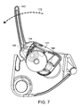
- the elongated section extends from the camming mechanism at least as long as the lengthwise dimension of the camming mechanism ( Figure 7 ).
- the lever arm 162 is shaped and coupled in a specific configuration to enable a mechanical advantage for rotation of the camming mechanism 140 when the lever mechanism 160 is extended.
- the lever mechanism 160 may be selectively extended by the belayer when the camming mechanism 140 is in the cammed state (ie. after a fall) and the belayer wishes to selectively allow the rope 110 to translate through the system (ie.
- the belayer thereby rotates the lever arm 162 a particular angle or amount with respect to the camming mechanism 140 to the extended state, thereby causing the coupling between the lever arm 162 and the camming mechanism 140.
- the belayer may then continue rotating the lever 162 to selectively release the camming surface 142 from the rope 110 toward the free state.
- the lever disengagement mechanism will disengage the coupling between the lever arm 162 and the camming mechanism 140.
- the camming mechanism 140 will then automatically reengage the cammed state if either the rope maintains certain friction with the camming surface or if the rope accelerates or jerks in a particular manner.
- the lever disengagement mechanism will then permit the lever arm 162 to further rotate in the lever extension rotation 172 direction without affecting the camming mechanism.
- the lever disengagement mechanism will also permit the lever arm 162 to be reset by rotating in the lever retraction rotation 174 direction back to the retracted state of the lever mechanism 160.
- the specific operation of the lever mechanism 160 and lever disengagement mechanism will be further described below in reference to the cross-section and partially transparent views sequentially illustrated in Figures 6-11 .
- the lever disengagement mechanism further includes a lever link 164 and a cam link 166 disposed between the lever arm 162 and the camming mechanism 140.
- the lever link 164 and cam link 166 are positive geometrical members having a particular relative rotational position, orientation, and shape. Because of the internal positioning of the links 164, 166, certain components are made partially transparent for illustration.
- the lever link 164 is coupled to an interior surface of the lever arm 162.
- the cam link 166 is coupled to an interior surface of the cam mechanism 140.
- the geometric shape of the lever link 164 and cam link 166 correspond to the coupling of the lever arm 162 to the cam mechanism 140 across specific rotational angles.
- the lever disengagement mechanism may include a link recess 170 within the bottom plate 122 of the housing 120.
- the operational states illustrated in Figure 6-11 represent the most common sequence of usage and automatic operation of the lever mechanism 160 and lever disengagement mechanism, but it will be appreciated that other uses and/or operational sequences may be performed in accordance with embodiments of the present invention.
- the cross-sectional views are specifically sliced, made transparent, and otherwise manipulated to illustrate essential components of the system and are not necessarily to scale, nor do they necessarily represent actual operational scenarios. It will be appreciated that although the rope 110 is not illustrated in Figures 6-11 , the operation of the camming mechanism 140 in part depends on the rope 110.
- Figure 6 illustrates the camming mechanism 140 in the cammed state and the lever arm 162 rotated in the lever extension rotation 172 direction.
- Figure 6 illustrates a non-extended state of the lever mechanism 160 because the lever arm 162 has not yet been rotated in the lever extension rotation 172 direction a sufficient amount or angle with respect to the camming mechanism 140 to cause the coupling between the lever arm 162 and the camming mechanism 140.
- the lever link 164 is rotationally separated from the cam link 166, thereby preventing the coupling between the lever arm 162 and camming mechanism 140.
- the links 164, 166 are specifically orientated such that the lever arm 162 may be rotated from the entirely retracted position ( Figures 1-4 ) to the illustrated position without affecting the camming mechanism 140.
- the camming mechanism 140 therefore remains in the illustrated cammed state.
- One of the reasons for the minimum lever arm 162 rotation prior to coupling is the proper orientation of the elongated portion of the lever arm 162 with respect to the camming mechanism 140 and coupling scheme between the camming mechanism 140 and the housing 120.
- the lever arm 162 must generate a mechanical advantage over the camming mechanism 140, and therefore maximum leverage is achieved by extending the elongated portion furthest from the rotation point 146 between the camming mechanism 140 and housing 120.
- Figures 7-8 illustrate the camming mechanism 140 in the cammed state and the lever arm 162 rotated further in the lever extension rotation 172 direction.
- the lever link 164 is rotated via the lever arm 162 to a position rotationally adjacent to the cam link 166, thereby engaging the coupling between the lever arm 162 and the camming mechanism 140.
- Figure 8 specifically illustrates how the lever arm 162 is rotated about the housing coupling 168 but is also rotated with respect to the camming mechanism 140.
- the links 164, 166 are specifically shaped and oriented on the lever arm 162 and camming mechanism 140 to bear on one another and create the rotational coupling between the lever arm 162 and the camming mechanism 140.
- the coupling is “unidirectional”, “releasable”, and “one-way”.
- the coupling is “unidirectional” because it only permits a single direction for joined rotation.
- the coupling is “releasable” because it is only engaged across certain rotational angles and may be released by the lever disengagement mechanism.
- the coupling is “one-way” because the camming mechanism 140 may still be rotated without the lever arm 162.
- the angle of the lever arm 162 elongated portion is substantially oriented to maximize the spacing from the cam rotation point 146 to induce the mechanical advantage discussed above that enables a user to release the camming mechanism 140.
- the relative positioning of the links 164, 166 correspond to the mechanical advantage of the lever arm 162 with respect to the camming mechanism 140.
- the engagement of the links 164, 166 and the resulting rotational coupling between the lever arm 162 and the camming mechanism 140 allow a user to rotate the lever arm 162 in the lever extension rotation 172 direction and cause the camming mechanism 140 to correspondingly rotate in the cam free rotation 152 direction.
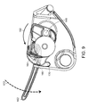
- Figure 9 illustrates the camming mechanism 140 substantially in the free state and the lever arm 162 rotated further in the lever extension rotation 172 direction.
- the coupling between lever mechanism 160 and the camming mechanism 140 via the lever link 164 and cam link 166 is maintained as the lever arm 162 is rotated from the position illustrated in Figures 7-8 to the position illustrated in Figure 9 .
- the rotation of the lever arm 162 from the position illustrated in Figures 7-8 to the position in Figure 9 allows the user to translate the camming mechanism 140 to the substantial free state via rotation about the cam rotation point 146.
- the free state of the camming mechanism 140 refers to a range of angles of the camming mechanism 140 with respect to the housing 120.
- the illustrated free state of the camming mechanism 140 includes translating the camming surface 142 from the rope channel 128, permitting a rope 110 (not shown) to translate with minimal friction.
- the lever link 164 and cam link 166 are about to rotationally translate past one another, thereby engaging the lever disengagement mechanism.
- the links 164, 166 are shaped and oriented to maintain a bearing coupling upon one another as the lever arm 162 is rotated across the angles corresponding to Figures 7-8 through Figure 9 .
- the cam link 166 is rotated into the link recess 170 of the housing in Figure 9 .
- the lever disengagement mechanism includes the specific shape, position, orientation, and alignment of the links 164, 166 to maintain the coupling between the lever mechanism 160 and the camming mechanism 140 across the range of lever arm 162 rotation and/or angles between Figures 7-9 .
- the spring biasing mechanism which biases the lever in the retracted position also prevents jamming as the lever link slips past the cam link.
- Figure 10 illustrates the camming mechanism rotated in the cam camming rotation 150 about the cam rotation point 146 back to the cammed state after the lever disengagement mechanism disengaged the coupling between the lever mechanism 160 and the camming mechanism 140.
- the lever disengagement mechanism includes the shape, position, orientation, and alignment of the links 164, 166 to allow the lever link 164 to rotationally translate past (ie. slip) the cam link, thereby disengaging the coupling between the lever mechanism 160 and the camming mechanism 140.
- the camming mechanism 140 independently returned to cammed state as a result of the rope 110 (not shown).
- lever arm 162 Since the lever arm 162 is disengaged from the camming mechanism 140 as a result of the lever disengagement mechanism, the lever arm 162 is able to independently rotate in the lever extension rotation 172 direction to a stop in the housing.
- the engagement of the lever disengagement mechanism allows the camming mechanism 140 to rotate in the opposite direction of the lever arm 162 because of the disengagement of the coupling.
- the novel operation of the lever disengagement mechanism therefore acts as a safety mechanism to reengage the automatic braking assistance of the camming mechanism in the event of the lever arm 162 being rotated beyond an acceptable angle.
- Figure 11 illustrates resetting the lever mechanism 160 with respect to the camming mechanism 140 after the lever disengagement mechanism was engaged ( Figure 10 ).
- the lever arm 162 is rotated in the lever retraction rotation 174 direction toward the retracted state illustrated in Figures 1-4 , and the lever links 164, 166 are rotationally translated past one another.
- the camming mechanism 140 is independently functioning and in the cammed state resulting from the lever disengagement mechanism.
- the lever disengagement mechanism includes the shape, position, orientation, and alignment of the links 164, 166 to permit the reset of the lever mechanism 160 and lever arm 162 back toward the retracted state.
- Resetting the lever disengagement mechanism means that the belayer may then proceed with re-rotating the lever away from the housing to the extended position so as to re-engage the lever link with the cam link. It is not necessary to completely rotate the lever arm 162 back to the retracted state illustrated in Figures 1-4 to reset the lever disengagement mechanism of the illustrated embodiment. As the lever arm 162 is rotated in the lever retraction rotation 174 back to reset the lever disengagement mechanism, the lever link 164 will automatically rotate within the lever arm 162 to facilitate sliding around the cam link 166 and prevent binding.
- the lever mechanism 160 may be reset by rotating the lever arm 162 back toward the retracted position a particular amount to translate the lever link 164 past the cam link 166. After the lever arm 162 is reset back toward the retracted state, the user may resume operation of the lever mechanism 160 ( Figure 6-9 ).
- One non-illustrated alternative embodiment includes an alternative lever disengagement mechanism, including a translating lever link that levers off the back plate of the device rather than a portion of the camming mechanism. The lever link slides in and out of the camming mechanism to allow engagement/disengagement between the lever and the camming mechanism.
- the alternative lever disengagement mechanism does not depend on different rotations of the camming mechanism with respect to the housing.
- lever link rotation with respect to the back plate, which pushes the translating piece into a recess in the lever until there is no longer contact with camming mechanism.
- Another non-illustrated alternative embodiment includes a lever disengagement mechanism in which the lever is rotatably coupled to the camming mechanism rather than the housing, and the lever link leverages off the back plate.
Landscapes
- Health & Medical Sciences (AREA)
- General Health & Medical Sciences (AREA)
- Business, Economics & Management (AREA)
- Emergency Management (AREA)
- Emergency Lowering Means (AREA)
Applications Claiming Priority (2)
| Application Number | Priority Date | Filing Date | Title |
|---|---|---|---|
| US201361785770P | 2013-03-14 | 2013-03-14 | |
| US14/206,418 US20140262610A1 (en) | 2013-03-14 | 2014-03-12 | Systems for Assisted Braking Belay with a Lever Disengagement Mechanism |
Publications (1)
| Publication Number | Publication Date |
|---|---|
| EP2777772A2 true EP2777772A2 (de) | 2014-09-17 |
Family
ID=50272463
Family Applications (1)
| Application Number | Title | Priority Date | Filing Date |
|---|---|---|---|
| EP14159573.6A Withdrawn EP2777772A2 (de) | 2013-03-14 | 2014-03-13 | Bremssysteme für das assistierte Abseilen mit einem Hebelentkopplungsmechanismus |
Country Status (2)
| Country | Link |
|---|---|
| US (1) | US20140262610A1 (de) |
| EP (1) | EP2777772A2 (de) |
Cited By (4)
| Publication number | Priority date | Publication date | Assignee | Title |
|---|---|---|---|---|
| FR3032354A1 (fr) * | 2015-02-11 | 2016-08-12 | Zedel | Dispositif assureur descendeur sur corde a demultiplication et blocage anti-panique |
| FR3059559A1 (fr) * | 2016-12-07 | 2018-06-08 | Zedel | Descendeur autobloquant |
| WO2018111676A1 (en) * | 2016-12-16 | 2018-06-21 | 3M Innovative Properties Company | Fall-protection apparatus with braking system |
| WO2018131038A1 (en) * | 2017-01-12 | 2018-07-19 | Highnovate | Quick release auto-blocking belay device |
Families Citing this family (8)
| Publication number | Priority date | Publication date | Assignee | Title |
|---|---|---|---|---|
| US9623269B2 (en) * | 2013-03-14 | 2017-04-18 | Black Diamond Equipment, Ltd. | Systems for assisted braking belay with a cam-clutch mechanism |
| GB2522179B (en) * | 2013-11-14 | 2019-02-13 | Int Safety Components Ltd | Improvements in and relating to rope descenders |
| US11660475B2 (en) | 2015-04-07 | 2023-05-30 | Harken, Incorporated | High load descender with adaptive release linkage |
| US10583315B2 (en) * | 2015-04-07 | 2020-03-10 | Harken, Incorporated | High load descender with adaptive release linkage |
| CA2982124C (en) * | 2015-04-07 | 2023-04-25 | Harken, Incorporated | High load descender with adaptive release linkage |
| PL3115084T3 (pl) * | 2015-07-08 | 2020-06-01 | Safety Engineering Ltd. | Układ do autoasekuracji do zastosowań wspinaczkowych |
| WO2024187123A1 (en) * | 2023-03-08 | 2024-09-12 | Buckingham Manufacturing Co., Inc. | Line climbing and dual action locking device |
| US12128258B1 (en) | 2023-04-25 | 2024-10-29 | Sherrill, Inc. | Descent control device |
Family Cites Families (11)
| Publication number | Priority date | Publication date | Assignee | Title |
|---|---|---|---|---|
| GB1222952A (en) * | 1967-04-04 | 1971-02-17 | Harley Patents Int | Releasable fasteners |
| US4542884A (en) * | 1983-06-06 | 1985-09-24 | Dodge Jr Cleveland E | Removable double action rope grip |
| FR2815876B1 (fr) * | 2000-11-02 | 2003-01-17 | Protecta Internat Sa | Procede pour la securite des personnes et dispositif |
| AU2002341670A1 (en) * | 2001-09-14 | 2003-04-01 | Safe Stop Systems, Inc. | Descent control device |
| US7055651B2 (en) * | 2003-09-09 | 2006-06-06 | Simple Little Gizmos Llc | Belay device |
| US8348016B2 (en) * | 2009-08-26 | 2013-01-08 | Lewis Richard W | Descender with fall arrest and controlled rate of descent |
| FR2950536B1 (fr) * | 2009-09-25 | 2011-10-07 | Zedel | Dispositif d'assurance autobloquant pour corde |
| US8733504B2 (en) * | 2012-01-17 | 2014-05-27 | Kirk Mauthner | Method and apparatus for a compact descender |
| DE102012207223B3 (de) * | 2012-04-30 | 2013-09-26 | Bornack Gmbh & Co. Kg | Sicherungsvorrichtung |
| FR3000898B1 (fr) * | 2013-01-16 | 2015-06-26 | Zedel | Appareil de securite sur corde a voyant indicateur de l'etat indicateur de l'etat de fermeture des flasques |
| US10760336B2 (en) * | 2013-06-28 | 2020-09-01 | 3M Innovative Properties Company | Fall arrester |
-
2014
- 2014-03-12 US US14/206,418 patent/US20140262610A1/en not_active Abandoned
- 2014-03-13 EP EP14159573.6A patent/EP2777772A2/de not_active Withdrawn
Non-Patent Citations (1)
| Title |
|---|
| None |
Cited By (13)
| Publication number | Priority date | Publication date | Assignee | Title |
|---|---|---|---|---|
| FR3032354A1 (fr) * | 2015-02-11 | 2016-08-12 | Zedel | Dispositif assureur descendeur sur corde a demultiplication et blocage anti-panique |
| EP3056248A1 (de) | 2015-02-11 | 2016-08-17 | Zedel | Sicherungs- und abseilgerät über ein seil mit übersetzung und anti-panik-blockade |
| US10716960B2 (en) | 2015-02-11 | 2020-07-21 | Zedel | Belay descender device on a rope with gearing-down and anti-panic blocking |
| US10682535B2 (en) | 2016-12-07 | 2020-06-16 | Zedel | Self-locking descender |
| CN108159585A (zh) * | 2016-12-07 | 2018-06-15 | 齐德公司 | 自锁下降器 |
| EP3332839A1 (de) * | 2016-12-07 | 2018-06-13 | Zedel | Selbstblockierendes abseilgerät |
| FR3059559A1 (fr) * | 2016-12-07 | 2018-06-08 | Zedel | Descendeur autobloquant |
| CN108159585B (zh) * | 2016-12-07 | 2022-06-21 | 齐德公司 | 自锁下降器 |
| WO2018111676A1 (en) * | 2016-12-16 | 2018-06-21 | 3M Innovative Properties Company | Fall-protection apparatus with braking system |
| AU2017376676B2 (en) * | 2016-12-16 | 2019-07-11 | 3M Innovative Properties Company | Fall-protection apparatus with braking system |
| CN110072595A (zh) * | 2016-12-16 | 2019-07-30 | 3M创新有限公司 | 具有制动系统的坠落保护设备 |
| US11065477B2 (en) | 2016-12-16 | 2021-07-20 | 3M Innovative Properties Company | Fall-protection apparatus with braking system |
| WO2018131038A1 (en) * | 2017-01-12 | 2018-07-19 | Highnovate | Quick release auto-blocking belay device |
Also Published As
| Publication number | Publication date |
|---|---|
| US20140262610A1 (en) | 2014-09-18 |
Similar Documents
| Publication | Publication Date | Title |
|---|---|---|
| EP2777772A2 (de) | Bremssysteme für das assistierte Abseilen mit einem Hebelentkopplungsmechanismus | |
| US9623269B2 (en) | Systems for assisted braking belay with a cam-clutch mechanism | |
| US9289634B2 (en) | Safety apparatus on a rope with indicator for indicating the state of closing of the flange-plates | |
| CN103816649B (zh) | 悬于绳索上在负荷下闭锁的安全装置 | |
| EP2953690B1 (de) | Energieabsorberanordnung und komponenten davon | |
| US9003617B2 (en) | Multi-chamber carabiner | |
| EP3013436B1 (de) | Fangvorrichtung | |
| EP1927767B1 (de) | Karabinerhaken | |
| US10092781B2 (en) | High load descender with adaptive release linkage | |
| CN110892172B (zh) | 防坠落装置连接器 | |
| EP3432992B1 (de) | Schiffchen für ein kletterschutzsystem | |
| US20170189725A1 (en) | High load descender with adaptive release linkage | |
| JP2004144292A (ja) | 固定ザイル用落下防止装置 | |
| EP2777773A2 (de) | Bremssysteme für das assistierte Abseilen mit einem Nocken-Kupplungsmechanismus | |
| EP2230419B1 (de) | Schleife mit verstellbarer Länge | |
| EP3281676B1 (de) | Steigklemme | |
| EP4079377B1 (de) | Verbindervorrichtungen | |
| WO2013053685A2 (en) | Fall arrest device | |
| EP2641635A2 (de) | Sicherheitsgerät für die Nutzung mit Zugangsseilen | |
| US11524185B2 (en) | Closure system | |
| EP3626311B1 (de) | Fallschutzvorrichtung für vertikale rettungsleinen | |
| EP4335519A2 (de) | Auslösevorrichtung zur verwendung mit einer sturzsicherungseinheit mit ausfahrbarer rettungsleine | |
| RU153435U1 (ru) | Замок десантно-спусковой | |
| US20250137500A1 (en) | Connector apparatus |
Legal Events
| Date | Code | Title | Description |
|---|---|---|---|
| 17P | Request for examination filed |
Effective date: 20140313 |
|
| AK | Designated contracting states |
Kind code of ref document: A2 Designated state(s): AL AT BE BG CH CY CZ DE DK EE ES FI FR GB GR HR HU IE IS IT LI LT LU LV MC MK MT NL NO PL PT RO RS SE SI SK SM TR |
|
| AX | Request for extension of the european patent |
Extension state: BA ME |
|
| PUAI | Public reference made under article 153(3) epc to a published international application that has entered the european phase |
Free format text: ORIGINAL CODE: 0009012 |
|
| STAA | Information on the status of an ep patent application or granted ep patent |
Free format text: STATUS: THE APPLICATION IS DEEMED TO BE WITHDRAWN |
|
| 18D | Application deemed to be withdrawn |
Effective date: 20161001 |