EP2777850B1 - Dispositif de serrage ou de préhension - Google Patents
Dispositif de serrage ou de préhension Download PDFInfo
- Publication number
- EP2777850B1 EP2777850B1 EP14160131.0A EP14160131A EP2777850B1 EP 2777850 B1 EP2777850 B1 EP 2777850B1 EP 14160131 A EP14160131 A EP 14160131A EP 2777850 B1 EP2777850 B1 EP 2777850B1
- Authority
- EP
- European Patent Office
- Prior art keywords
- base body
- clamping jaws
- gripping device
- guide
- axially
- Prior art date
- Legal status (The legal status is an assumption and is not a legal conclusion. Google has not performed a legal analysis and makes no representation as to the accuracy of the status listed.)
- Active
Links
Images









Classifications
-
- B—PERFORMING OPERATIONS; TRANSPORTING
- B23—MACHINE TOOLS; METAL-WORKING NOT OTHERWISE PROVIDED FOR
- B23B—TURNING; BORING
- B23B31/00—Chucks; Expansion mandrels; Adaptations thereof for remote control
- B23B31/02—Chucks
- B23B31/10—Chucks characterised by the retaining or gripping devices or their immediate operating means
- B23B31/12—Chucks with simultaneously-acting jaws, whether or not also individually adjustable
- B23B31/16—Chucks with simultaneously-acting jaws, whether or not also individually adjustable moving radially
- B23B31/16233—Jaws movement actuated by oblique surfaces of a coaxial control rod
-
- B—PERFORMING OPERATIONS; TRANSPORTING
- B23—MACHINE TOOLS; METAL-WORKING NOT OTHERWISE PROVIDED FOR
- B23B—TURNING; BORING
- B23B31/00—Chucks; Expansion mandrels; Adaptations thereof for remote control
- B23B31/02—Chucks
- B23B31/10—Chucks characterised by the retaining or gripping devices or their immediate operating means
- B23B31/12—Chucks with simultaneously-acting jaws, whether or not also individually adjustable
- B23B31/16—Chucks with simultaneously-acting jaws, whether or not also individually adjustable moving radially
- B23B31/16233—Jaws movement actuated by oblique surfaces of a coaxial control rod
- B23B31/16254—Jaws movement actuated by oblique surfaces of a coaxial control rod using fluid-pressure means to actuate the gripping means
-
- B—PERFORMING OPERATIONS; TRANSPORTING
- B23—MACHINE TOOLS; METAL-WORKING NOT OTHERWISE PROVIDED FOR
- B23B—TURNING; BORING
- B23B31/00—Chucks; Expansion mandrels; Adaptations thereof for remote control
- B23B31/02—Chucks
- B23B31/10—Chucks characterised by the retaining or gripping devices or their immediate operating means
- B23B31/12—Chucks with simultaneously-acting jaws, whether or not also individually adjustable
- B23B31/16—Chucks with simultaneously-acting jaws, whether or not also individually adjustable moving radially
- B23B31/16233—Jaws movement actuated by oblique surfaces of a coaxial control rod
- B23B31/16266—Jaws movement actuated by oblique surfaces of a coaxial control rod using mechanical transmission through the spindle
-
- B—PERFORMING OPERATIONS; TRANSPORTING
- B24—GRINDING; POLISHING
- B24B—MACHINES, DEVICES, OR PROCESSES FOR GRINDING OR POLISHING; DRESSING OR CONDITIONING OF ABRADING SURFACES; FEEDING OF GRINDING, POLISHING, OR LAPPING AGENTS
- B24B41/00—Component parts such as frames, beds, carriages, headstocks
- B24B41/06—Work supports, e.g. adjustable steadies
- B24B41/066—Work supports, e.g. adjustable steadies adapted for supporting work in the form of tools, e.g. drills
Definitions
- the present invention relates to a clamping or gripping device according to the preamble of claims 1 and 7 with a base of a dimensionally stable material which defines a longitudinal axis, a plurality of clamping jaws which are held on the base body movable radially with respect to the longitudinal axis, and at least one partially hollow clamping piston, which is held on the main body axially movable between a rear and a front end position and the clamping jaws at least partially surrounds, wherein the clamping jaws and the clamping piston are coupled together in such a way that an axial movement of the clamping piston in a radial movement of the clamping jaws is implemented, and wherein an actuator is provided for actuating the tensioning piston.
- a device is from the document DE 408 900 C known.
- Clamping or gripping device of this type are known and are used in particular as a precision chuck for grinding tools.
- the applicant distributes such precision chucks under the brand Prismo.
- These chucks comprise a base body made of a dimensionally stable material which has a central receptacle open to the front end face of the main body and defining a longitudinal axis of the chuck.
- a plurality of, in the Prismo clamping devices of the Applicant exactly five, clamping jaws are arranged and held radially movable with respect to the longitudinal axis of the chuck.
- the known chucks have an at least partially hollow clamping piston, which is placed in the central receptacle of the base body and held axially movable between a rear and a front end position.
- the tensioning piston has five axial passage openings, which are penetrated by the clamping jaws, so that they protrude forward from the clamping piston and can escape from this.
- the clamping piston and the clamping jaws are provided with mutually corresponding inclined surfaces which cooperate with each other in such a way that an axial adjusting movement of the clamping piston are converted into corresponding radial movements of the clamping jaws. To guide the radial movements of the clamping jaws these have on their radial outer side prismatic guide surfaces, which are in engagement with corresponding guide surfaces of the clamping piston.
- Object of the present invention is therefore to provide a clamping or gripping device of the type mentioned in such a way that with high clamping precision and small diameter components that are sensitive to pressure, can be stretched.
- the base body has on its rear side a central recess in which an associated with the tensioning piston, annular connecting element is axially guided, that in the main body an axis is held, that on the axis an intermediate axis is held axially displaceable, which passes through the connecting element axially that spring elements, in particular compression spring elements are provided, which are supported between the connecting element and the intermediate axis to push the connecting element to the rear, wherein stop means are provided which an axial displacement of the connecting element to the rear limit, and that the rear end of the base body is closed, so that between the connecting element and the housing body at the back of the connecting element in the central recess, a pressure space is formed, which is acted upon via a pressure line from the outside with a pressure to the connecting element against the restoring force to move the spring elements forward.
- the workpiece is stretched over the spring elements.
- the pressure chamber which is formed on the back of the connecting element, via the provided pressure line from the outside with a pressure (hydraulic or pneumatic) is applied to push the connecting element from its rear end position, which is defined by the stop means to the front and so open the chuck.
- the connecting element is pushed back by the restoring force of the spring elements to close the chuck and so to clamp a component.
- the fixation of the component takes place with the spring force of the spring elements.
- the working stroke of the connecting element can be specified by a corresponding positioning of the stop means and a corresponding stop surface of the intermediate axis, on which the spring elements are supported. This makes it possible to set relatively small clamping distances of a few millimeters. This simplifies the clamping of small components. Likewise, by appropriate selection of the spring elements and the clamping force can be selected low, so that even sensitive components can be stretched without the risk of damage.
- the clamping diameter range can be specified by the intermediate axis is adjusted axially.
- the intermediate axis may have at its front end portion an external thread which is screwed into a corresponding threaded bore of the guide pin, so that the intermediate axis can be adjusted axially by turning about its longitudinal axis.
- the intermediate axle can have corresponding engagement means for a rotary tool at its front end region.
- the intermediate axle may have an axially displaceably but non-rotatably held sleeve element on the axle and a threaded head fixed to the free end of the sleeve element, which has an external thread engaging with the threaded bore of the guide pin.
- the stop means may be provided in particular in the form of a radially projecting shoulder at the rear end region of the intermediate axis.
- an intermediate sleeve is pushed onto the intermediate axis and bears against an axial stop of the intermediate axis at its front end region, the spring elements being supported between the connecting element and the intermediate sleeve.
- the intermediate sleeve is held by the spring elements in constant attack on the intermediate axis.
- the annular gap which exists between the connecting element and the intermediate axis is sealed in order to prevent that compressed air from the pressure chamber at the back of the connecting element to the front, which could lead to malfunction.
- the connecting element can be sealed on the outside with respect to the base body.
- a threaded bolt on the axis axially fixed, but is rotatably supported about its longitudinal axes and the intermediate shaft is screwed onto the threaded bolt, so that the intermediate axis is axially adjustable by turning the threaded bolt, and that drive means are provided to to turn the threaded bolt.
- a ring gear can be rotatably held, which is displaceable from the outside in particular by an actuating opening on the base body by means of an actuating element in rotation.
- the sprocket may have a spur gear.
- the object of the present invention is further achieved according to claim 7, characterized in that the base body has on its rear side a central recess in which a piston connected to the connecting element is held, in particular axially guided, and the connecting element has an internal thread into which a threaded bolt is screwed, which is rotatably supported in the body, but axially fixed, and that drive means are provided to rotate the threaded bolt.
- a ring gear can be rotatably held on the threaded bolt, which is displaceable from the outside in particular by an actuating opening in the base body, by means of an actuating element in rotation.
- the sprocket may be formed, for example in the form of a spur gear.
- an actuating element such as an actuating key, which has a toothing corresponding to the spur toothing of the sprocket, inserted into the base body and in engagement with the sprocket through the actuating opening in the body brought.
- the threaded bolt is rotated.
- the connecting element which can not rotate, moves axially together with the associated clamping piston, and this axial movement of the clamping piston is converted into a corresponding radial movement of the clamping jaws.
- the tensioning piston expediently carries at its rear end a plurality of axially extending struts, which pass through correspondingly axial passage openings in the base body, wherein the struts are connected to one another at their free ends by the connecting element, for example screwed.
- the function of the connecting element is essentially to connect the clamping piston with a corresponding actuator.
- the recess has such a depth that in the rear position of the clamping piston, the free ends of the struts or that the free ends of the struts connecting connecting element are still within the recess.
- the recess initially has the purpose of receiving an actuator for actuating the tensioning piston in whole or in part.
- the connecting element can be guided axially in the central recess.
- the tensioning piston is then guided over the recess. This reduces the diameter / length ratio.
- a central receptacle in which the clamping jaws and the clamping piston are arranged.
- a guide pin projecting coaxially to the longitudinal axis protrudes from the base body, on the outside of which the tensioning piston is guided in an axially movable manner. This embodiment is based on the consideration, no longer make the leadership of the clamping piston on its outer surface, but to shift inward by the tensioning piston is guided on the guide pin provided according to the invention. As a result of the displacement of the guide inward, the diameter / length ratio of the guide decreases, as a result of which a high degree of guiding stability and quality is achieved.
- the base body is axially divided and has a recording defining base body member and a guide pin supporting body member, wherein the two base body elements aligned by corresponding centering means to each other and releasably connected, in particular screwed. Due to the split design of the base body, a simple production, in particular of the guide pin is achieved.
- the guide pin is sleeve-shaped and protrudes at its front end portion of the main body, wherein longitudinal slots are provided in the wall of the guide pin, which are penetrated by the clamping jaws.
- This embodiment provides the ability to bring the jaws together until they touch each other.
- the longitudinal slots are expediently open to the front end side of the guide pin.
- the clamping piston axial Vietnamese skillsöff openings may have, which are penetrated by the clamping jaws, so that they can protrude forward from the clamping piston.
- the passage openings can be designed so that the jaws are guided in them laterally.
- the clamping jaws each have a guide surface on a side surface, in which engages an associated guide nose of the clamping piston, wherein each guide nose cooperates with guide surfaces of the associated guide groove to implement axial movements of the clamping piston in radial movements of the clamping jaws.
- the guide grooves are in a preferred manner only on a side surface of the clamping jaws, and that on the side surface which faces in the direction of the counterclockwise direction in the plan view formed. This embodiment is based on the consideration, the guide surfaces of the clamping jaws, which are provided in the known chucks on the radially outer side of the clamping jaws to move radially further inward into the side surfaces. This reduces the diameter / length ratio of the jaw guides, whereby an increased stability and guiding accuracy is achieved.
- each guide groove has a radially inner guide surface and a radially outer guide surface and the associated guide nose is in contact with both guide surfaces, so that a forward axial movement of the clamping piston by an interaction of the outer surface of the guide nose with the radially outer guide surface of the guide groove is converted into a radially outwardly directed movement of the clamping jaws and a rearwardly directed axial movement of the clamping piston is converted by a cooperation of the inner surface of the guide nose with the radially inner guide surface in a radially inwardly directed clamping movement of the clamping jaw.
- the guide lugs are formed at a front end portion of the tensioning piston or at the front end of the through openings, which are penetrated by the clamping jaws.
- the engagement between the guide lugs and the guide grooves of the clamping jaws takes place radially as far inside as possible, so that the diameter / length ratio of the jaw guides is minimized. Furthermore, a maximum guide length is ensured.
- the clamping jaws with their rear end surface lie flat against a contact surface, which is perpendicular to the longitudinal axis, of the base body, in particular of a base body element carrying the guide pin. Compressive forces, which lead to the jaws are thus introduced directly into the body.
- a radial groove may be formed in a side surface of the clamping jaws, in which engages a holding web to secure the clamping jaw axially against the contact surface.
- the retaining bar has no leadership, but only a backup function.
- the radial grooves may expediently be formed on the same side surface of the clamping jaws as the guide grooves. Then only one-sided machining of the jaws for the preparation of the grooves is required.
- the retaining webs may be formed on retaining elements, which are screwed to the base body and in particular to the guide pin bearing rear body member.
- the clamping or gripping device according to the invention comprises three or more jaws.
- exactly five or exactly six clamping jaws can be provided.
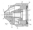
- FIGS. 1 to 11 a first embodiment of a clamping or gripping device according to the invention according to the present invention is shown.
- the chuck comprises a base body 1 made of a dimensionally stable material, which has a cylindrical basic shape.
- a central receptacle 2 is formed, which defines a longitudinal axis X of the chuck and is open to a front end face of the base body 1.
- a clamping piston 3 is inserted and therein axially, ie in the direction of the longitudinal axis X, between a rear and a front end position kept movable.
- the tensioning piston 3 has a cylindrical basic shape, but the front end surface tapers frustoconically to the front end.
- the chuck further comprises a total of five clamping jaws 4, which are also positioned in the central receptacle 2 of the base body 1 and radially movable together between an outer, open position and an inner clamping position.
- the clamping jaws 4 are encompassed by the clamping piston 3 and are in corresponding through holes 5 of the clamping piston 3, which are axially penetrated by the clamping jaws 4, so that they protrude forward from the clamping piston 3, held.
- the clamping jaws 4 are guided and supported laterally in the passage openings 5.
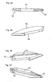
- the clamping jaws 4 run while pointed at its upper end and define at the region of their front ends radially inwardly facing clamping surfaces 4a.
- clamping jaws 4 have on their radial outer side an inclined outer surface 4c and on its radial inner side below the clamping surfaces 4a an inclined inner surface 4b.
- the these radially inner and outer surfaces 4b, 4c associated walls of the clamping piston 3, which define the through holes 5 of the clamping piston 3, are inclined accordingly.
- the main body 1 is divided axially and has a front, sleeve-like design and the receptacle 2 defining base body element 1a, and a rear base body element 1b, wherein the two basic body elements 1a, 1b coaxially aligned with each other and releasably connected, are screwed here.
- an annular shoulder is formed on the rear base body element 1 b, which engages in the receptacle 2 of the front body member 1 a.
- the rear body member 1b carries on its front end face which is positioned in the central receptacle 2, a guide pin 7 which is sleeve-like and engages the receptacle 2.
- the outer surface of the guide pin 7 forms a cylindrical guide surface on which the clamping piston 3 is guided axially movable.
- the clamping piston 3 has a corresponding guide surface 8.
- a total of five longitudinal slots 9 are provided, which are open to the front side of the guide pin 7 and are penetrated radially by the clamping jaws 4.
- the clamping jaws 4 each have in their side surface, which in the plan view of FIG. 5 in the counterclockwise direction, a guide groove 10.
- the guide grooves 10 each extend from the rear end face of the clamping jaws 4 to just below the front end and are inclined to the longitudinal axis X of the chuck aligned. The inclination corresponds to the inclination of the inclined inner and outer surfaces 4b, 4c of the clamping jaws 4.
- the guide grooves 10 are each assigned a guide nose 11, which is held on the clamping piston 3 and positioned at the radially inner end of the through holes 5 of the clamping piston 3 and engage in the guide grooves 10.
- each guide groove 10 has a radially inner guide surface 10a and a radially outer guide surface 10b and the associated guide lug 11 is in contact with both guide surfaces 10a, 10b, so that a forward axial movement of the clamping piston 3 by an interaction of the outer surface of the guide lug 11th is reacted with the radially outer guide surface 10b of the guide groove 10 in a radially outward movement of the clamping jaws 4 and in the reverse manner, a rearward axial movement of the clamping piston 3 by cooperation of the inner surface of the guide lug 11 with the radially inner guide surface 10a of the guide 10th in a radially inward direction Clamping movement of the clamping jaws 3 is implemented.
- these axial movements of the clamping piston 3 is guided inside on the guide pin 7. Due to the small diameter of the guide sleeve 7 and the available guide length results in a good diameter / length ratio for the guide, so that it is stable.
- the jaws 4 can also be moved completely together, so that even very small diameter can be stretched. Due to the radially far inner position of the guide lugs 11 and the diameter / length ratio of the guides for the clamping jaws 4 is small, so that a high stability is achieved. It is also advantageous that the guide lugs 11 at the axially front end and thus in the region of the clamping surfaces 4a, where the highest guidance accuracy is required lie.
- the jaws 4 each with their rear end face against a lying perpendicular to the longitudinal axis X contact surface of the rear body member 1b, which is here formed by the front end face of the rear body member 1 b. Furthermore, at the rear end of the clamping jaws 4 are each a radial groove 12 in that side surface of the clamping jaws 4, in which the guide grooves 10 are formed, is provided. In the radial groove 12 engages a holding web 13 in order to secure the clamping jaws 4 axially to the contact surface. The holding webs 13 are formed on holding elements 14, which are screwed to the rear body member 1b.
- this carries at its rear end a plurality of axially extending struts 15, which pass through corresponding axial through holes 16 in the rear body member 1b.
- the struts 15 are connected together at their free ends by a connecting ring 17, which on the struts 15, namely the facing the back faces of the struts 15, is screwed.
- the connecting ring 17 is held axially displaceably in a central recess 18, which is formed in the rear body member 1b and open to the rear side.
- a not shown here actuator which may be formed, for example in the form of a motor, a hydraulic drive or the like, a.
- a total of five lubricating nipples 19 are provided on the clamping piston 3, via which a lubricant can be supplied to the through-openings 5 of the clamping piston 3, in which the clamping jaws 4 are positioned.
- FIGS. 12 to 19 a second embodiment of a chuck according to the invention is shown. This corresponds to the previously based on the FIGS. 1 to 10 described embodiment. The only difference is that a manual actuator for adjusting the clamping piston 3 is provided.
- This comprises a threaded bolt 20 which is rotatably but axially retained in the rear body member 1 b. Concretely, the threaded bolt 20 is rotatably supported at its front end in the guide sleeve 7, and at its rear end, it is fixed in a lid 21 which closes the recess 18 of the rear body member 1b at its open rear side.
- the threaded bolt 20 here is formed in two parts and comprises a first threaded bolt element 20a, which is held on the cover 21, and a second threaded bolt element 20b, which is pushed onto the first threaded bolt element 20a and held against rotation therewith.
- the second threaded bolt element 20b has an external thread 22, which passes through the connecting ring 17 and is screwed into this, for which the connecting ring 17 is provided with a corresponding internal thread.
- the second threaded bolt element 20b further includes a sprocket 23, which protrudes radially outwards and carries a spur toothing 24 on its forwardly facing end face.
- an actuating opening is provided in the base body 1, in which an actuating element 25 is inserted and rotatably supported.
- the actuator 25 carries at its end projecting into the base 1 a toothing 26 which is in engagement with the spur gear teeth 24 of the ring gear 23, so that rotation of the actuating element 25 about its axis in a rotational movement of the ring gear 23 and thus the threaded bolt 20 to the longitudinal axis X in an axial movement of the connecting ring 17, which can not rotate, is reacted, with the result that the clamping piston 3 is moved axially.
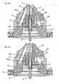
- FIGS. 20 to 28 a third embodiment of a chuck according to the invention is shown. This differs from the previously described embodiments substantially only in terms of the design of the actuator for the clamping piston 3. This is in a central recess 18 of the base body 1, here the rear base member 1 b housed, which closed at its open back by a cover 21 is.
- the actuator comprises an axis 27 which is held on the cover 21 at a central position, ie coaxially with the longitudinal axis X, and projects into the recess 18.
- an intermediate axis 28 is held axially displaceable, wherein the intermediate axis 28 at its front end has an external thread 29 which is screwed into a corresponding threaded bore 30 of the hollow guide pin 7 formed.
- the intermediate shaft 28 includes a sleeve member 28a axially slidably supported on the drive shaft 27 and a threaded head fixed to the free end of the sleeve member 28a 28 b, which has a with the threaded bore 30 of the guide pin 7 in engagement male thread.
- the intermediate shaft 28 passes through the connecting ring 17 axially, wherein an annular gap formed between the components is sealed airtight.
- the intermediate axis 28 in turn carries an intermediate sleeve 31, which is pushed onto the intermediate shaft 28.
- the intermediate sleeve 31 is located at its upper end to a corresponding shoulder of the intermediate axis 28, which is here formed by the threaded head 28 b, and has at its lower end a contact flange 31 a.
- the actuator further comprises a plurality of spring elements, here compression spring elements 32, which are supported between the connecting element 17 and the abutment flange 31 a.
- the compression spring elements 32 are positioned in corresponding bores of the connecting element 17 and are supported at their upper end region on the abutment flange 31a of the intermediate sleeve 31, so that it is held in abutment with the threaded head 28b.
- the compression spring elements 32 cause the connecting element 17 is pushed backwards.
- 28 stop means 33 are provided at the rear end portion of the intermediate axis, which are formed here in the form of a radially projecting shoulder.
- the region of the recess 18 provided on the rear side of the connecting element 17 is designed as a pressure chamber 34, which can be acted on from the outside by a pressure via a pressure line 34a.
- FIG. 26 the clamping device is shown in a starting position, in which the pressure chamber 34 is depressurized and, accordingly, the connecting element 17 is pressed by the force of the compression spring elements 32 down against the axial stop 33 of the intermediate shaft 28. If the Pressure chamber 34 now with a pressure medium, compressed air is applied here, the connecting element 17 and thus the clamping piston 3 against the restoring force of the compression spring elements 32 from the in FIG. 26 position shown in the in FIG. 23 raised position shown, whereby the jaws 4 are slightly opened to use a component can. If the pressure chamber 34 is then relieved again, the connecting element 17 is pressed down by the restoring force of the compression spring elements 32, so that the clamping jaws 4 are closed in order to clamp a component positioned between them. The fixation of the component between the clamping jaws 4 takes place solely by the spring force of the compression spring elements 32nd
- the position of the intermediate axis 28 is changed with the connecting element 17 held thereon.
- a hexagon socket wrench is inserted from above through the guide sleeve 7 in a corresponding engagement region 35 of the threaded head 28b in order to turn it further down. This is right up in the FIG. 28 shown lower end position possible, in which the connecting element 17 rests almost on the lid 21. A small residual gap must be present so that compressed air can still get between the cover 21 and the connecting element 17.
- clamping jaws 4 are opened according to the adjustment, so that a component between the clamping jaws 4 can be used. If subsequently the pressure chamber is relieved, the connecting element 17 and thus the clamping piston 3 by the restoring force of the Compression spring elements 32 lowered again, so that the component is fixed between the clamping jaws 4,
- the clamping force can be set individually by compression spring elements 32 corresponding stiffness can be used.
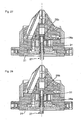
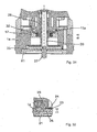
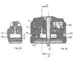
- FIGS. 29 to 35 a fourth embodiment of a chuck according to the invention is shown, which differs from the embodiments described above substantially in terms of the design of the actuator for the clamping piston 3.
- This actuator is technically a combination of the actuators of the second and third embodiment.
- the clamping piston 3 is housed in a central recess 18 of the base body 1, here the rear base member 1b, which is closed at its open back by a cover 21.
- the actuator comprises an axis 27, which is held on the cover 21 at a central position, ie coaxially with the longitudinal axis X and projects into the recess 18.
- a threaded bolt 20 is held axially fixed but rotatable.
- the threaded bolt 20 is rotatably supported at its front end in the guide sleeve 7, and at its rear end, it is pushed onto the axis 27.
- an intermediate shaft 28 is held, which is screwed onto the threaded bolt 20.
- the intermediate shaft 28 passes through the connecting ring 17 axially, wherein an annular gap formed between the components is sealed airtight.
- the threaded bolt 20 carries at its lower end portion a ring gear 23 which protrudes radially outwardly and carries on its front end face a spur gear 24.
- an actuating opening is provided in the base body 1, in which an actuating element 25 is inserted and held rotatably.
- the actuator 25 carries at its end projecting into the base 1 a toothing 26 which is in engagement with the spur gear teeth 24 of the ring gear 23, so that rotation of the actuating element 25 about its axis in a rotational movement of the ring gear 23 and thus the threaded bolt 20 and the longitudinal axis X is implemented.
- the rotational movement of the threaded bolt 20 in turn leads to an axial adjustment of the intermediate axis 28.
- the actuator further comprises a plurality of compression spring elements 32, which are supported between the connecting element 17 and the intermediate axis 28.
- the compression spring elements 32 are positioned in corresponding bores of the connecting element 17 and are supported at their upper end region on a bearing flange provided on the intermediate axis 28.
- the compression spring elements 32 cause the connecting element 17 is pushed backwards.
- the connection path is limited to the rear by a shoulder 15a, 15 provided on the clamping piston struts 15, which pass through the corresponding axial passage openings 16 in the rear body member 1b. These are in FIG. 31 recognizable.
- the region of the recess 18 provided on the rear side of the connecting element 17 is designed as a pressure chamber 34, which can be acted on from the outside by a pressure via a pressure line 34a.
- FIG. 33 the clamping device is shown in a starting position, in which the intermediate axis 28 is moved to its foremost position and the pressure chamber 34 is depressurized. Accordingly, the connecting element 17 is pressed by the force of the compression spring elements 32 down. In this case, the adjustment is limited because the paragraphs 15a of the struts 15 come into contact with the abutment flange in the intermediate axis 28.
- the connecting element 17 and thus the clamping piston 3 against the restoring force of the compression spring elements 32 from the in FIG. 33 position shown in the in FIG. 31 raised position shown, whereby the jaws 4 are slightly opened to use a component can. If the pressure chamber 34 is then relieved again, the connecting element 17 is pressed down by the restoring force of the compression spring elements 32, so that the clamping jaws 4 are closed in order to clamp a component positioned between them.
- the position of the intermediate axis 28 is adjusted by the threaded bolt 20 is rotated via the actuating element 25.
- the connecting element 17 is shown in the lowermost position.
Landscapes
- Engineering & Computer Science (AREA)
- Mechanical Engineering (AREA)
- Jigs For Machine Tools (AREA)
Claims (17)
- Dispositif de serrage ou de préhension avec un châssis (1) composé d' un matériau rigide définissant un axe longitudinal (X), plusieurs mâchoires de serrage (4) montées sur le châssis (1) et mobiles en directement radiale par rapport à l'axe longitudinal (X), et un piston de serrage (3) au moins partiellement creux monté mobile axialement sur le châssis (1) entre une position de fin de course arrière et une position de fin de course avant et enveloppant au moins partiellement les mâchoires de serrage (4), les mâchoires de serrage (4) et le piston de serrage (3) étant couplés de façon à donner lieu à un mouvement axial du piston de serrage (3) lors du mouvement radial des mâchoires de serrage (4), et une commande d'entrainement étant prévue pour l'actionnement du piston de serrage (3), caractérisé en ce que le dos du châssis (1) présente une exclusion (18) dans laquelle est inséré axialement un élément de raccordement annulaire (17) relié au piston de serrage (3), que le châssis (1) comporte un axe (27), que l'axe (27) comporte un axe intermédiaire (28) axialement mobile qu' enveloppe axialement l'élément de raccordement (17), que sont prévus des éléments de ressort, notamment des éléments de ressort à pression (32), qui viennent s' appuyer entre l'élément de raccordement (17) et l'axe intermédiaire (28) afin de pousser l'élément de raccordement (17) vers l'arrière, des moyens d' arrimage (33) étant en place pour limiter le déplacement axial de l'élément de raccordement (17) vers l'arrière, et que l'extrémité arrière du châssis (1) est refermée de sorte que soit formée, dans l'exclusion centrale (18), entre l'élément de raccordement (17) et le boîtier (1) à l'arrière de l'élément de raccordement (17), une chambre de pression (34) prouvant être ouverte de l'extérieur sous l'action d' une pression transmise par une conduite de pression afin de déplacer l'élément de raccordement (17) vers l'avant contre la force de rappel des éléments à ressort (32).
- Dispositif de serrage ou de préhension selon la revendication 1, caractérisé en ce que l'extrémité avant de l'axe intermédiaire (28) présente un filetage extérieur (29) vissé dans un perçage taraudé (30) correspondant du tenon de guidage (7), de sorte que l'axe intermédiaire (28) puisse être déplacé axialement le long de son axe longitudinal par pivotement.
- Dispositif de serrage ou de préhension selon la revendication 2, caractérisé en ce que l'axe intermédiaire (28) comprend un élément de manchon (28a) monté de façon non rotative sur l'axe (27) sur lequel il peut être déplacé axialement, ainsi qu'une tête de taraudage (28b) fixée sur l'extrémité libre de l'élément de manchon (28) et présentant un filetage extérieur engagé avec le perçage taraudé (30) du tenon de guidage (7), et/ou qu'une section arrière de l'axe intermédiaire (28) comporte les moyens d' arrimage (33), notamment sous la forme d' un épaulement radialement en saillie.
- Dispositif de serrage ou de préhension selon l'une des revendications précédentes, caractérisé en ce qu' un manchon intermédiaire (31) est enfilé sur l' axe intermédiaire (28) et touche, de sa section avant, une butée axiale de l'axe intermédiaire (28), les éléments de ressort à pression (32) s'appuyant entre l'élément de raccordement (17) et le manchon intermédiaire (31) et/ou qu' est colmaté un espace annulaire entre l'élément de raccordement (17) et l'axe intermédiaire (18).
- Dispositif de serrage ou de préhension selon la revendication 2, caractérisé en ce que sont disposés, sur le front avant de l'axe intermédiaire (28), ou plus précisément d' une tête de taraudage (28b) de l'axe intermédiaire (28), des moyens d' engrènement pour un outil rotatif permettant de faire pivoter l'axe intermédiaire (28) dans le but de le déplacer axialement par rapport au châssis (1).
- Dispositif de serrage ou de préhension selon la revendication 2, caractérisé en ce qu' un boulon fileté (20) est fixé à l'axe (27) de façon amovible dans la direction axial, mais rotative le long de l'axe longitudinal, et que l'axe intermédiaire (28) est vissé au boulon fileté (20) de sorte que l'axe intermédiaire (28) peut être décalé en faisant pivoter le boulon fileté (20), et que des moyens d' entraînement sont en place pour faire pivoter le boulon fileté (20),
sur le boulon fileté (20) étant notamment montée non pivotante une couronne dentée (23) qui est notamment mise en rotation de l'extérieur au moyen d' un élément d' actionnement (25) par une ouverture d' actionnement dans le châssis (1), et la couronne dentée (23) présentant idéalement une denture frontale (24). - Dispositif de serrage ou de préhension avec un châssis (1) composé d'un matériau rigide définissant un axe longitudinal (X), plusieurs mâchoires de serrage (4) montées sur le châssis (1) et mobiles en directement radiale par rapport à l'axe longitudinal (X), et un piston de serrage (3) au moins partiellement creux monté mobile axialement sur le châssis (1) entre une position de fin de course arrière et une position de fin de course avant et enveloppant au moins partiellement les mâchoires de serrage (4), les mâchoires de serrage (4) et le piston de serrage (3) étant couplés de façon à donner lieu à un mouvement axial du piston de serrage (3) lors du mouvement radial des mâchoires de serrage (4), et une commande d'entraînement étant prévue pour l'actionnement du piston de serrage (3), caractérisé en ce que le dos du châssis (1) présente une exclusion(18) dans laquelle est maintenu, ou plus précisément inséré axialement, un élément de raccordement annulaire (17) relié au piston, et que l'élément de raccordement (17) présente un filetage interne dans lequel est vissé un boulon fileté (20) prouvant être pivoté dans le châssis (1) mais étant autrement immobile dans la direction axiale, et que des moyens d' entraînement sont en place pour faire pivoter le boulon fileté (20).
- Dispositif de serrage ou de préhension selon la revendication 7, caractérisé en ce que, sur le boulon fileté (20) est montée non pivotante une couronne dentée (23) qui est notamment mise en rotation de l'extérieur au moyen d' un élément d' actionnement (25) par une ouverture d' actionnement dans le châssis (1), la couronne dentée (23) présentant notamment une denture frontale (24).
- Dispositif de serrage ou de préhension selon l'une des revendications précédentes, caractérisé en ce que l'extrémité arrière du piston de serrage (3) présente plusieurs entretoises (15) qui s'étendent en direction axiale, traversant le châssis (1) par des ouvertures de passage (5) axiales correspondantes et étant reliées entre elles par leurs extrémités libres au moyen de l'élément de raccordement (17), les entretoises (15) aboutissant dans l'exclusion (18) du châssis (1), la profondeur de l'exclusion (18) étant telle que dans la position arrière du piston de serrage (3), les extrémités libres des entretoises ou l'élément de raccordement (17) reliant lesdites entretoises (15) sont quand même contenus dans l'exclusion (18).
- Dispositif de serrage ou de préhension selon l'une des revendications précédentes, caractérisé en ce que le front du châssis (1) présente un logement central (2) dans lequel les mâchoires de serrage (4) et le piston de serrage (3) sont disposés.
- Dispositif de serrage ou de préhension selon l'une des revendications précédentes, caractérisé en ce que du châssis (1) saillit un tourillon de guidage (7) disposé coaxialement à l'axe longitudinal (X) et dans le côté externe duquel le piston de serrage (3) est monté de façon mobile dans le sens axial, le châssis (1) étant notamment subdivisé axialement et présentant un élément de châssis (1a) définissant le logement (2) ainsi qu'un élément de châssis (1 b) portant le tourillon de guidage (7), les deux éléments de châssis (1a, 1b) étant reliés, ou plus précisément vissés, et raccordés entre eux de façon amovible par des moyens de centrage (6).
- Dispositif de serrage ou de préhension selon la revendication 11, caractérisé en ce que le tourillon de guidage (7) a une forme de manchon et que son extrémité avant est en saillie par rapport au châssis (1), la paroi du tourillon de guidage (7) présentant des fentes longitudinales (9) travées par les mâchoires de serrage (3), les fentes longitudinales (9) étant notamment ouvertes sur le front avant du tourillon de guidage (7).
- Dispositif de serrage ou de préhension selon l'une des revendications précédentes, caractérisé en ce que le piston de serrage (3) présente des ouvertures de passage (5) traversées par les mâchoires de serrage (4) de sorte que ces dernières saillissent du piston de serrage (3) et dans lesquelles les mâchoires de serrage (4) sont notamment insérées latéralement.
- Dispositif de serrage ou de préhension selon la revendication 11, caractérisé en ce que les mâchoires de serrage (4) présentent chacune sur un côté une rainure de guidage (10) dans laquelle vient s'engager un ergot de guidage (11) du piston de serrage (3) qui lui est assigné, chaque ergot de guidage (11) interagissant avec les surfaces de guidage (10a, 10b) de la rainure de guidage (10) qui lui est assignée afin de transposer des mouvements axiaux du piston de serrage (3) en mouvement radiaux des mâchoires de serrage (4), les rainures de guidage (10) étant formées dans une paroi latérale des mâchoires de serrage (4), ou plus précisément dans la paroi latérale qui, vue du dessus, est orientée dans la direction du sens horaire opposé.
- Dispositif de serrage ou de préhension selon la revendication 14, caractérisé en ce que chaque rainure de guidage présente une surface de guidage (10a) radialement interne ainsi qu' une surface de guidage (10b) radialement externe et que l'ergot de guidage (11) assigné est en contact avec les deux surfaces de guidage (10a, 10b) de sorte qu' un mouvement axial vers l'avant du piston de serrage (3) est transposé en un mouvement radial vers l'extérieur des mâchoires de serrage (4) par l'interaction de la surface extérieure (11b) de l'ergot de guidage (11) avec la surface de guidage (10b) de la rainure de guidage (10), et qu' un mouvement axial vers l'arrière du piston de serrage (3) est transposé en un mouvement radial vers l'intérieur des mâchoires de serrage (4) par l'interaction de la surface intérieure (11a) de l'ergot de guidage (11) avec la surface de guidage intérieure (10a), les ergots de guidage (11) étant notamment configurés sur l'extrémité avant du piston de serrage (3).
- Dispositif de serrage ou de préhension selon l'une des revendications précédentes, caractérisé en ce que la surface frontale arrière des mâchoires de serrage (4) touche à plat à une surface de contact du châssis (1), plus précisément de l'élément de châssis (1b) portant le tenon de guidage (7), verticale à l'axe longitudinal (X).
- Dispositif de serrage ou de préhension selon la revendication 16, caractérisé en ce qu'une rainure radiale (12) est pratiquée à l'extrémité arrière de la mâchoire de serrage (3) dans chaque surface latérale de la mâchoire de serrage (3), dans laquelle une entretoise de maintien (13) vient s'engager pour immobiliser la mâchoire de serrage (3) axialement à la surface de contact,
les rainures radiales (12) étant chacune réalisées dans la même paroi latérale des mâchoires de serrage (4), comme les rainures de guidage (10), et/ou
les entretoises de maintien (13) étant notamment disposés sur des éléments de maintien (14) solidement vissés au châssis (1), et notamment à l'élément de châssis (1 b) supportant le tenon de guidage (7).
Applications Claiming Priority (1)
| Application Number | Priority Date | Filing Date | Title |
|---|---|---|---|
| DE201320002445 DE202013002445U1 (de) | 2013-03-14 | 2013-03-14 | Spann- oder Greifeinrichtung |
Publications (2)
| Publication Number | Publication Date |
|---|---|
| EP2777850A1 EP2777850A1 (fr) | 2014-09-17 |
| EP2777850B1 true EP2777850B1 (fr) | 2015-08-12 |
Family
ID=50277121
Family Applications (1)
| Application Number | Title | Priority Date | Filing Date |
|---|---|---|---|
| EP14160131.0A Active EP2777850B1 (fr) | 2013-03-14 | 2014-03-14 | Dispositif de serrage ou de préhension |
Country Status (2)
| Country | Link |
|---|---|
| EP (1) | EP2777850B1 (fr) |
| DE (1) | DE202013002445U1 (fr) |
Families Citing this family (2)
| Publication number | Priority date | Publication date | Assignee | Title |
|---|---|---|---|---|
| CN104308780B (zh) * | 2014-10-29 | 2015-10-28 | 哈尔滨工业大学 | 基于力封闭多点随动的长轴标准器精密装夹方法与装置 |
| CN110125843B (zh) * | 2019-06-14 | 2020-12-29 | 重庆东科模具制造有限公司 | 一种圆柱形工件夹持装置 |
Family Cites Families (11)
| Publication number | Priority date | Publication date | Assignee | Title |
|---|---|---|---|---|
| DE408900C (de) * | 1921-06-04 | 1925-01-27 | Aufspann Werkzeuge Ag | Spannvorrichtung |
| GB1381146A (en) * | 1972-05-16 | 1975-01-22 | Clarke Chapman Ltd | Chuck |
| DE7710804U1 (de) * | 1977-04-05 | 1977-09-22 | Jagenberg-Werke Ag, 4000 Duesseldorf | Spannkopf fuer huelsen |
| DE3048274A1 (de) * | 1980-12-20 | 1982-07-29 | Otto 8961 Reicholzried Zettl | Bohrfutter |
| GB2178984B (en) * | 1985-08-16 | 1989-08-02 | Kitagawa Iron Works Co | Chucks for machine tools |
| DE4114884C2 (de) * | 1991-05-07 | 1997-05-22 | Hans Nos | Verfahren zum Spannen eines Werkstückes und Spannvorrichtung zu seiner Durchführung |
| DE4209307C2 (de) * | 1992-03-21 | 1995-05-11 | Albrecht Josef Bohrfutter | Bohrfutter |
| DE19836912A1 (de) * | 1998-08-14 | 2000-02-24 | Schunk Fritz Gmbh | Spannfutter, insbesondere Dehnspannfutter |
| JP2001259909A (ja) * | 2000-03-13 | 2001-09-25 | Pascal Kk | チャック装置 |
| DE102006037708A1 (de) * | 2006-08-08 | 2008-02-14 | Schunk Gmbh & Co. Kg Spann- Und Greiftechnik | Schnellspanneinheit, Verschlusseinheit hierfür und Schnellspannsystem |
| JP5227341B2 (ja) * | 2008-01-24 | 2013-07-03 | 株式会社コスメック | クランプ装置 |
-
2013
- 2013-03-14 DE DE201320002445 patent/DE202013002445U1/de not_active Expired - Lifetime
-
2014
- 2014-03-14 EP EP14160131.0A patent/EP2777850B1/fr active Active
Also Published As
| Publication number | Publication date |
|---|---|
| DE202013002445U1 (de) | 2014-06-16 |
| EP2777850A1 (fr) | 2014-09-17 |
Similar Documents
| Publication | Publication Date | Title |
|---|---|---|
| DE102011052967B4 (de) | Presszange, Wechselkassette für eine Presszange und Presszangenset | |
| EP2370222B1 (fr) | Porte-outil | |
| DE60037950T2 (de) | Bohrantrieb Futter | |
| EP0507147A1 (fr) | Accouplement | |
| WO2009043407A1 (fr) | Système de montage et démontage rapide | |
| EP3191245B1 (fr) | Mandrin de serrage | |
| WO2020245000A1 (fr) | Clé de service pour porte-outils fixes et entraînés | |
| DE60001337T2 (de) | Bohrfutter | |
| EP2777848B1 (fr) | Dispositif de serrage ou de préhension | |
| EP2777849B1 (fr) | Dispositif de serrage ou de préhension | |
| EP1709931B1 (fr) | Organe moteur, en particulier pièce à main dentaire avec un accouplement détachable pour un porte-outil | |
| DE112004002051T5 (de) | Kraftbegrenzende Werkstück-Haltevorrichtung | |
| EP2777850A1 (fr) | Dispositif de serrage ou de préhension | |
| EP1660262B1 (fr) | Point d'assemblage d'un outil | |
| DE29708201U1 (de) | Schrittweiser kraftverstärkender Schraubstock in Planetengetriebezug-Bauart | |
| EP1709930A1 (fr) | Organe moteur, en particulier pièce à main médicale avec une pince de serrage | |
| WO2019020786A1 (fr) | Outil d'usinage par enlèvement de copeaux | |
| DE102017213047A1 (de) | Justiereinrichtung für ein zerspanungswerkzeug und zerspanungswerkzeug mit einer justiereinrichtung | |
| DE1810722B2 (de) | Spannfutter | |
| DE10260493A1 (de) | Kraftspannfutter und Ausklinkschlüssel dafür | |
| DE2916179C2 (de) | Spanneinrichtung, insbesondere Maschinenschraubstock | |
| DE2343723C3 (de) | Schraubstock u.dgl. Spanngerät | |
| EP1157767A1 (fr) | Mandrin de serrage | |
| CH690542A5 (de) | Werkstückspannvorrichtung für eine Werkzeugmaschine. | |
| DE102022114975A1 (de) | Spannvorrichtung zum Einspannen eines Wechselkörpers an einer Spannfläche und Kombination aus einer solchen Spannvorrichtung und einem Wechselkörper |
Legal Events
| Date | Code | Title | Description |
|---|---|---|---|
| 17P | Request for examination filed |
Effective date: 20140314 |
|
| AK | Designated contracting states |
Kind code of ref document: A1 Designated state(s): AL AT BE BG CH CY CZ DE DK EE ES FI FR GB GR HR HU IE IS IT LI LT LU LV MC MK MT NL NO PL PT RO RS SE SI SK SM TR |
|
| AX | Request for extension of the european patent |
Extension state: BA ME |
|
| PUAI | Public reference made under article 153(3) epc to a published international application that has entered the european phase |
Free format text: ORIGINAL CODE: 0009012 |
|
| RIN1 | Information on inventor provided before grant (corrected) |
Inventor name: UEBELE, ANDRE |
|
| RIN1 | Information on inventor provided before grant (corrected) |
Inventor name: UEBELE, ANDRE |
|
| GRAP | Despatch of communication of intention to grant a patent |
Free format text: ORIGINAL CODE: EPIDOSNIGR1 |
|
| R17P | Request for examination filed (corrected) |
Effective date: 20141229 |
|
| RBV | Designated contracting states (corrected) |
Designated state(s): AL AT BE BG CH CY CZ DE DK EE ES FI FR GB GR HR HU IE IS IT LI LT LU LV MC MK MT NL NO PL PT RO RS SE SI SK SM TR |
|
| INTG | Intention to grant announced |
Effective date: 20150212 |
|
| GRAS | Grant fee paid |
Free format text: ORIGINAL CODE: EPIDOSNIGR3 |
|
| GRAP | Despatch of communication of intention to grant a patent |
Free format text: ORIGINAL CODE: EPIDOSNIGR1 |
|
| GRAA | (expected) grant |
Free format text: ORIGINAL CODE: 0009210 |
|
| INTG | Intention to grant announced |
Effective date: 20150703 |
|
| AK | Designated contracting states |
Kind code of ref document: B1 Designated state(s): AL AT BE BG CH CY CZ DE DK EE ES FI FR GB GR HR HU IE IS IT LI LT LU LV MC MK MT NL NO PL PT RO RS SE SI SK SM TR |
|
| REG | Reference to a national code |
Ref country code: GB Ref legal event code: FG4D Free format text: NOT ENGLISH |
|
| REG | Reference to a national code |
Ref country code: CH Ref legal event code: EP |
|
| REG | Reference to a national code |
Ref country code: AT Ref legal event code: REF Ref document number: 741679 Country of ref document: AT Kind code of ref document: T Effective date: 20150815 |
|
| REG | Reference to a national code |
Ref country code: IE Ref legal event code: FG4D Free format text: LANGUAGE OF EP DOCUMENT: GERMAN |
|
| REG | Reference to a national code |
Ref country code: DE Ref legal event code: R096 Ref document number: 502014000070 Country of ref document: DE |
|
| REG | Reference to a national code |
Ref country code: LT Ref legal event code: MG4D Ref country code: FR Ref legal event code: PLFP Year of fee payment: 3 |
|
| REG | Reference to a national code |
Ref country code: NL Ref legal event code: MP Effective date: 20150812 |
|
| PG25 | Lapsed in a contracting state [announced via postgrant information from national office to epo] |
Ref country code: LV Free format text: LAPSE BECAUSE OF FAILURE TO SUBMIT A TRANSLATION OF THE DESCRIPTION OR TO PAY THE FEE WITHIN THE PRESCRIBED TIME-LIMIT Effective date: 20150812 Ref country code: LT Free format text: LAPSE BECAUSE OF FAILURE TO SUBMIT A TRANSLATION OF THE DESCRIPTION OR TO PAY THE FEE WITHIN THE PRESCRIBED TIME-LIMIT Effective date: 20150812 Ref country code: FI Free format text: LAPSE BECAUSE OF FAILURE TO SUBMIT A TRANSLATION OF THE DESCRIPTION OR TO PAY THE FEE WITHIN THE PRESCRIBED TIME-LIMIT Effective date: 20150812 Ref country code: GR Free format text: LAPSE BECAUSE OF FAILURE TO SUBMIT A TRANSLATION OF THE DESCRIPTION OR TO PAY THE FEE WITHIN THE PRESCRIBED TIME-LIMIT Effective date: 20151113 Ref country code: NO Free format text: LAPSE BECAUSE OF FAILURE TO SUBMIT A TRANSLATION OF THE DESCRIPTION OR TO PAY THE FEE WITHIN THE PRESCRIBED TIME-LIMIT Effective date: 20151112 |
|
| PG25 | Lapsed in a contracting state [announced via postgrant information from national office to epo] |
Ref country code: HR Free format text: LAPSE BECAUSE OF FAILURE TO SUBMIT A TRANSLATION OF THE DESCRIPTION OR TO PAY THE FEE WITHIN THE PRESCRIBED TIME-LIMIT Effective date: 20150812 Ref country code: ES Free format text: LAPSE BECAUSE OF FAILURE TO SUBMIT A TRANSLATION OF THE DESCRIPTION OR TO PAY THE FEE WITHIN THE PRESCRIBED TIME-LIMIT Effective date: 20150812 Ref country code: PL Free format text: LAPSE BECAUSE OF FAILURE TO SUBMIT A TRANSLATION OF THE DESCRIPTION OR TO PAY THE FEE WITHIN THE PRESCRIBED TIME-LIMIT Effective date: 20150812 Ref country code: IS Free format text: LAPSE BECAUSE OF FAILURE TO SUBMIT A TRANSLATION OF THE DESCRIPTION OR TO PAY THE FEE WITHIN THE PRESCRIBED TIME-LIMIT Effective date: 20151212 Ref country code: SE Free format text: LAPSE BECAUSE OF FAILURE TO SUBMIT A TRANSLATION OF THE DESCRIPTION OR TO PAY THE FEE WITHIN THE PRESCRIBED TIME-LIMIT Effective date: 20150812 Ref country code: RS Free format text: LAPSE BECAUSE OF FAILURE TO SUBMIT A TRANSLATION OF THE DESCRIPTION OR TO PAY THE FEE WITHIN THE PRESCRIBED TIME-LIMIT Effective date: 20150812 Ref country code: PT Free format text: LAPSE BECAUSE OF FAILURE TO SUBMIT A TRANSLATION OF THE DESCRIPTION OR TO PAY THE FEE WITHIN THE PRESCRIBED TIME-LIMIT Effective date: 20151214 |
|
| PG25 | Lapsed in a contracting state [announced via postgrant information from national office to epo] |
Ref country code: NL Free format text: LAPSE BECAUSE OF FAILURE TO SUBMIT A TRANSLATION OF THE DESCRIPTION OR TO PAY THE FEE WITHIN THE PRESCRIBED TIME-LIMIT Effective date: 20150812 |
|
| PG25 | Lapsed in a contracting state [announced via postgrant information from national office to epo] |
Ref country code: SK Free format text: LAPSE BECAUSE OF FAILURE TO SUBMIT A TRANSLATION OF THE DESCRIPTION OR TO PAY THE FEE WITHIN THE PRESCRIBED TIME-LIMIT Effective date: 20150812 Ref country code: EE Free format text: LAPSE BECAUSE OF FAILURE TO SUBMIT A TRANSLATION OF THE DESCRIPTION OR TO PAY THE FEE WITHIN THE PRESCRIBED TIME-LIMIT Effective date: 20150812 Ref country code: CZ Free format text: LAPSE BECAUSE OF FAILURE TO SUBMIT A TRANSLATION OF THE DESCRIPTION OR TO PAY THE FEE WITHIN THE PRESCRIBED TIME-LIMIT Effective date: 20150812 Ref country code: DK Free format text: LAPSE BECAUSE OF FAILURE TO SUBMIT A TRANSLATION OF THE DESCRIPTION OR TO PAY THE FEE WITHIN THE PRESCRIBED TIME-LIMIT Effective date: 20150812 |
|
| REG | Reference to a national code |
Ref country code: DE Ref legal event code: R097 Ref document number: 502014000070 Country of ref document: DE |
|
| PG25 | Lapsed in a contracting state [announced via postgrant information from national office to epo] |
Ref country code: RO Free format text: LAPSE BECAUSE OF FAILURE TO SUBMIT A TRANSLATION OF THE DESCRIPTION OR TO PAY THE FEE WITHIN THE PRESCRIBED TIME-LIMIT Effective date: 20150812 |
|
| PLBE | No opposition filed within time limit |
Free format text: ORIGINAL CODE: 0009261 |
|
| STAA | Information on the status of an ep patent application or granted ep patent |
Free format text: STATUS: NO OPPOSITION FILED WITHIN TIME LIMIT |
|
| 26N | No opposition filed |
Effective date: 20160513 |
|
| PG25 | Lapsed in a contracting state [announced via postgrant information from national office to epo] |
Ref country code: SI Free format text: LAPSE BECAUSE OF FAILURE TO SUBMIT A TRANSLATION OF THE DESCRIPTION OR TO PAY THE FEE WITHIN THE PRESCRIBED TIME-LIMIT Effective date: 20150812 Ref country code: BE Free format text: LAPSE BECAUSE OF NON-PAYMENT OF DUE FEES Effective date: 20160331 |
|
| PG25 | Lapsed in a contracting state [announced via postgrant information from national office to epo] |
Ref country code: LU Free format text: LAPSE BECAUSE OF FAILURE TO SUBMIT A TRANSLATION OF THE DESCRIPTION OR TO PAY THE FEE WITHIN THE PRESCRIBED TIME-LIMIT Effective date: 20160314 Ref country code: MC Free format text: LAPSE BECAUSE OF FAILURE TO SUBMIT A TRANSLATION OF THE DESCRIPTION OR TO PAY THE FEE WITHIN THE PRESCRIBED TIME-LIMIT Effective date: 20150812 |
|
| REG | Reference to a national code |
Ref country code: IE Ref legal event code: MM4A |
|
| REG | Reference to a national code |
Ref country code: FR Ref legal event code: PLFP Year of fee payment: 4 |
|
| PG25 | Lapsed in a contracting state [announced via postgrant information from national office to epo] |
Ref country code: IE Free format text: LAPSE BECAUSE OF NON-PAYMENT OF DUE FEES Effective date: 20160314 |
|
| PG25 | Lapsed in a contracting state [announced via postgrant information from national office to epo] |
Ref country code: MT Free format text: LAPSE BECAUSE OF FAILURE TO SUBMIT A TRANSLATION OF THE DESCRIPTION OR TO PAY THE FEE WITHIN THE PRESCRIBED TIME-LIMIT Effective date: 20150812 |
|
| REG | Reference to a national code |
Ref country code: FR Ref legal event code: PLFP Year of fee payment: 5 |
|
| PG25 | Lapsed in a contracting state [announced via postgrant information from national office to epo] |
Ref country code: SM Free format text: LAPSE BECAUSE OF FAILURE TO SUBMIT A TRANSLATION OF THE DESCRIPTION OR TO PAY THE FEE WITHIN THE PRESCRIBED TIME-LIMIT Effective date: 20150812 Ref country code: HU Free format text: LAPSE BECAUSE OF FAILURE TO SUBMIT A TRANSLATION OF THE DESCRIPTION OR TO PAY THE FEE WITHIN THE PRESCRIBED TIME-LIMIT; INVALID AB INITIO Effective date: 20140314 |
|
| PG25 | Lapsed in a contracting state [announced via postgrant information from national office to epo] |
Ref country code: CY Free format text: LAPSE BECAUSE OF FAILURE TO SUBMIT A TRANSLATION OF THE DESCRIPTION OR TO PAY THE FEE WITHIN THE PRESCRIBED TIME-LIMIT Effective date: 20150812 Ref country code: MK Free format text: LAPSE BECAUSE OF FAILURE TO SUBMIT A TRANSLATION OF THE DESCRIPTION OR TO PAY THE FEE WITHIN THE PRESCRIBED TIME-LIMIT Effective date: 20150812 |
|
| PG25 | Lapsed in a contracting state [announced via postgrant information from national office to epo] |
Ref country code: BG Free format text: LAPSE BECAUSE OF FAILURE TO SUBMIT A TRANSLATION OF THE DESCRIPTION OR TO PAY THE FEE WITHIN THE PRESCRIBED TIME-LIMIT Effective date: 20150812 |
|
| PG25 | Lapsed in a contracting state [announced via postgrant information from national office to epo] |
Ref country code: AL Free format text: LAPSE BECAUSE OF FAILURE TO SUBMIT A TRANSLATION OF THE DESCRIPTION OR TO PAY THE FEE WITHIN THE PRESCRIBED TIME-LIMIT Effective date: 20150812 |
|
| GBPC | Gb: european patent ceased through non-payment of renewal fee |
Effective date: 20180314 |
|
| PG25 | Lapsed in a contracting state [announced via postgrant information from national office to epo] |
Ref country code: GB Free format text: LAPSE BECAUSE OF NON-PAYMENT OF DUE FEES Effective date: 20180314 |
|
| P01 | Opt-out of the competence of the unified patent court (upc) registered |
Effective date: 20230628 |
|
| REG | Reference to a national code |
Ref country code: DE Ref legal event code: R081 Ref document number: 502014000070 Country of ref document: DE Owner name: SCHUNK SE & CO. KG SPANNTECHNIK GREIFTECHNIK A, DE Free format text: FORMER OWNER: SCHUNK GMBH & CO. KG SPANN- UND GREIFTECHNIK, 74348 LAUFFEN AM NECKAR, DE |
|
| PGFP | Annual fee paid to national office [announced via postgrant information from national office to epo] |
Ref country code: CH Payment date: 20250401 Year of fee payment: 12 |
|
| REG | Reference to a national code |
Ref country code: CH Ref legal event code: U11 Free format text: ST27 STATUS EVENT CODE: U-0-0-U10-U11 (AS PROVIDED BY THE NATIONAL OFFICE) Effective date: 20260401 |
|
| PGFP | Annual fee paid to national office [announced via postgrant information from national office to epo] |
Ref country code: DE Payment date: 20260319 Year of fee payment: 13 |
|
| PGFP | Annual fee paid to national office [announced via postgrant information from national office to epo] |
Ref country code: AT Payment date: 20260320 Year of fee payment: 13 |
|
| PGFP | Annual fee paid to national office [announced via postgrant information from national office to epo] |
Ref country code: IT Payment date: 20260324 Year of fee payment: 13 |
|
| PGFP | Annual fee paid to national office [announced via postgrant information from national office to epo] |
Ref country code: FR Payment date: 20260320 Year of fee payment: 13 |
|
| PGFP | Annual fee paid to national office [announced via postgrant information from national office to epo] |
Ref country code: TR Payment date: 20260309 Year of fee payment: 13 |